Taiwan RoHS Information
This appendix provides Taiwan RoHS information for the routers described in this guide.
For the Taiwan BSMI RoHS Table, go to https://www.arista.com/assets/data/pdf/AristaBSMIRoHS.pdf.
This appendix provides Taiwan RoHS information for the routers described in this guide.
For the Taiwan BSMI RoHS Table, go to https://www.arista.com/assets/data/pdf/AristaBSMIRoHS.pdf.
This section lists the Regulatory Model Number (RMN) of the routers described in this document.
| SKU | Regulatory Model Number (RMN) |
|---|---|
| AWE-5310-2F-FLX | AN1791 |
| AWE-5510-2F-FLX | AN1792 |
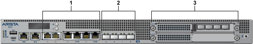
This section describes the operation of the LCD panel for the Arista 5310 and Arista 5510 Enterprise WAN Routers.
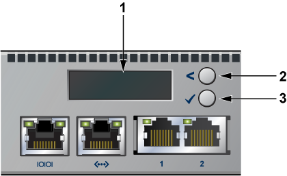
| 1 | 2x16 LCD screen |
| 2 | Top button |
| 3 | Bottom button |
Each button has a functionality based on the button and how long the button is pressed.
| Button | Press Duration
< 2 Secs |
Press Duration
>= 2 Secs |
|---|---|---|
| Top button | scroll | home |
| Bottom button | select | confirm |
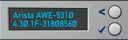
Once the power is on, the LCD displays the image shown below:
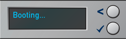
Once the bootloader is booted and when the EOS image has begun loading, the LCD displays the image shown below:

Once the EOS has successfully booted, the LCD displays the home screen. The following image is an example output:
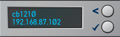
The first line displays the hostname, and the second line displays the IPv4 address of the management interface.
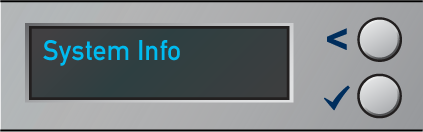
Starting at the home screen, use the top button (“scroll” function) to scroll through possible menu choices. The menu choice displays on the top line.
To select the menu item, press the bottom button (“select” function).
Although the physical display is limited to 2 rows and 16 characters per row, a menu item may display a larger virtual information display. If the width of the line being displayed is wider than the physical screen, then the display will automatically scroll back and forth to display the entire line.
If the number of lines displayed exceeds the physical height, then you can scroll through the output by using the LCD buttons. Use the top button (“scroll” function) to see earlier lines, and use the bottom button (“select” function) to see later lines.
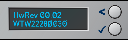
The System Info menu item shows the following information:
Model name
EOS version
Hardware revision
Serial number
MAC address of the management interface
The following figure shows the first two lines of the data:
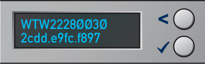
The following figure shows the data displayed after pressing the bottom button twice:
The following figure shows the data displayed after pressing the bottom button again:
This section describes the front panel ports of the following routers from a physical layer perspective. This section includes the following topics:
This section describes the front panel ports of the Arista 5310 Enterprise WAN Router from a physical layer perspective. This section includes the following topics:
Refer to the AWE-5310-2F-FLX section for detailed information.
The Arista 5310 Enterprise WAN Router provides 5 Gbps Encrypted / 30 Gbps aggregate throughput. It has 4xRJ45 (1/2.5 G/10G) Ethernet ports, 2x fail-to-wire (FTW) ports and 4x SFP+ (1/2.5G/10G) Ethernet ports, and 2x Network Interface Module (NIM) expansion slots. The ports are labeled 1, 2, 3, 3 FTW, 4, 4 FTW, 5, 6, 7, and 8.
In the EOS CLI, all the on-board ports have the prefix 1 (Et1/X, X from 1-8) to indicate they are on the main system, rather than the pluggable NIM cards.
| Label | Port Number | Port Type | EOS Interface |
|---|---|---|---|
| 1 |
1, 2, 3, 4 |
RJ45 | Et1/1, Et1/2, Et1/3, Et1/4 |
| 3FTW, 4FTW | Fail-to-wire | ||
| 2 |
5, 6, 7, 8 |
SFP+ | Et1/5, Et1/6, Et1/7, Et1/8 |
| 3 |
Slot 2, Slot 3 |
Network Interface Module (NIM) |
This section describes interface capabilities like speed and Forward Error Correction (FEC). For additional information, see the EOS User's Guide. These capabilities are displayed with the following command:
show interfaces <INTF> hardware defaultThe speed/auto-negotiation depends on the MAC/PHY capabilities, the front panel connector, and the type of transceiver inserted. The default capabilities of the Arista 5310 Enterprise WAN Router are as follows:
| Ports | Speed | Auto-negotiation |
|---|---|---|
| RJ45 (Et1/1-Et1/4) | 1G/2.5G/5G/10G full duplex | 1G/2.5G/5G/10G full duplex |
| SFP (Et1/5-Et1/8) | 1G/10G | 1G/10G full duplex
1G full duplex |
When a transceiver is inserted, EOS recognizes the transceiver type. To see which types of transceivers are supported, refer to the Supported Transceivers. EOS decides the capable speed/auto-negotiation that both the hardware and the modules satisfy. To view the show commands and example outputs, refer to the Show Commands for Speed and Auto-negotiation Capabilities.
When there is no speed configuration on the interface, EOS applies the default speed. On an RJ45 port, the default configuration is auto-negotiation enabled with 10G. On an SFP port, the default configuration is auto-negotiation disabled with 10G.
This section describes the configuration of interface speed and auto-negotiation.
Interface speed and auto-negotiation are configured using the speed speed-lane-token command as shown in the following examples:
To configure 10G speed with auto-negotiation disabled:
Arista(config-if-Et1/1)#speed 10gTo configure 1G speed with auto-negotiation disabled:
Arista(config-if-Et1/1)#speed 1gTo configure 10G speed with auto-negotiation enabled:
Arista(config-if-Et1/1)#speed auto 10gfullTo configure 5G speed with auto-negotiation enabled:
Arista(config-if-Et1/1)#speed auto 5gfullTo configure 2.5G speed with auto-negotiation enabled:
Arista(config-if-Et1/1)#speed auto 2.5gfullTo configure 1G speed with auto-negotiation enabled:
Arista(config-if-Et1/1)#speed auto 1gfullTo remove speed configuration:
Arista(config-if-Et1/1)#no speedUse the following show command to check whether interfaces are connected, not connected, or error-disabled:
Arista(config)#show interfaces status
Port Name Status Vlan Duplex SpeedType Flags Encapsulation
Et1/1 connectedrouted full 10G10GBASE-T
Et1/2 connectedrouted full 10G10GBASE-T
Et1/3 connectedrouted full 10G10GBASE-T
Et1/4 connectedrouted full 10G10GBASE-T
Et1/5 connectedrouted full 10G10GBASE-CR
Et1/6 connectedrouted full 10G10GBASE-CR
Et1/7 connectedrouted full 10G10GBASE-CR
Et1/8 errdisabledrouted full 100G 10GBASE-CR
Use the following show command to display why an interface is error-disabled:
Arista(config)#show interfaces ET1/8 status errdisabled
PortName Status Reason
----------- ---------------- ------------ -------------------
Et1/8errdisabled speed-misconfigured
When a transceiver is in an error-disabled state due to a misconfigured speed, the following syslog message is logged:
bessd[4392]: %ETH-4-LINKMODEUNSUPPORTED: Unsupported link mode 100G/full for interface Ethernet1/8
Ebra: %ETH-4-ERRDISABLE: speed-misconfigured error detected on Ethernet1/8.
Supported speed and auto-negotiation are displayed by the following command when the transceiver is inserted:
show interfaces <INTERFACES> hardwareRJ45 port output:
Arista(config)#show interfaces Et1/1 hardware Ethernet1/1
Model: AWE-5310
Type: 10GBASE-T
Speed/duplex: 1G/full,2.5G/full,5G/full,10G/full,auto(default)
Flowcontrol: rx-(off),tx-(off)
Error correction: unsupported
SFP port output:
Arista(config)#show interfaces Et1/5 hardware Ethernet1/5
Model: AWE-5310
Type: 10GBASE-CR
Speed/duplex: 10G/full(default)
Flowcontrol: rx-(off),tx-(off)
Error correction: unsupported
The on-board SFP ports support a wide range of 1G and 10G pluggable transceivers.
CAB-SFP-SFP (10GBASE-CR)
AOC-S-S-10G (10GBASE-AOC)
SFP-10G-SRL
SFP-10G-SR
SFP-10G-LRL
SFP-10G-LR
SFP-10G-ER
SFP-10G-ZR
SFP-10G-DZ (10GBASE-DWDM)
SFP-SFP-10G-T
SFP-1G-SX
SFP-1G-LX
SFP-1G-T
For details about the different transceiver modules and cables, visit https://www.arista.com/en/products/transceivers-cables.
This section describes the front panel ports of the Arista 5510 Enterprise WAN router from a physical layer perspective. This section includes the following topics:
Refer to the AWE-5510-2F-FLX section for detailed information.
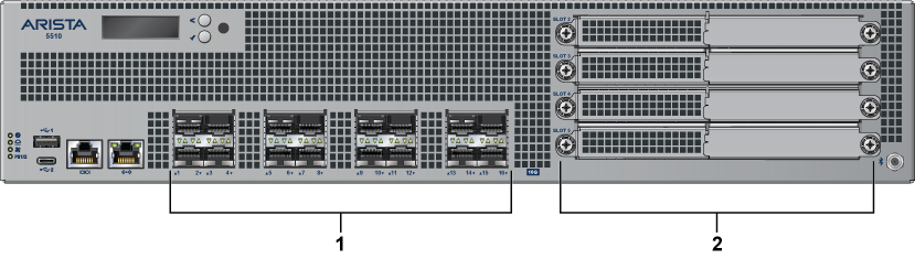
The Arista 5510 Enterprise WAN Router provides 50 Gbps Encrypted / 100 Gbps aggregate throughput. It has 16x 10G Ethernet ports (SFP+), and 4x Network Interface Module (NIM) expansion slots. The ports are labeled 1 through 16.
In the EOS CLI, all the onboard ports have the prefix 1 (Et1/X, X from 1-16) to indicate that they are on the main system rather than the pluggable NIM cards.
| Label | Port Number | Port Type | EOS Interface |
|---|---|---|---|
| 1 | 1, 2, 3, 4, 5, 6, 7, 8, 9, 10, 11, 12, 13, 14, 15, 16 | SFP+ | Et1/1, Et1/2, Et1/3, Et1/4, Et1/5, Et1/6, Et1/7, Et1/8, Et1/9, Et1/10, Et1/11, Et1/12, Et1/13, Et1/14, Et1/15, Et1/16 |
| 2 | Slot 2, Slot 3, Slot 4, Slot 5 | Network Interface Module (NIM) |
This section describes interface capabilities. These capabilities are displayed using the following command:
show interfaces <INTF> hardware defaultInterface speed and auto-negotiation depends on the MAC/PHY capabilities, the front panel connector, and the type of transceiver inserted. The default capabilities of the Arista 5510 Enterprise WAN Router are as follows:
| Ports | Speed | Auto-negotiation |
|---|---|---|
| Port 1-8 | 1G/10G | 1G full
1G full duplex |
| Port 9-16 | 1G/10G | 1G/10G full duplex
1G full duplex |
When a transceiver is inserted, EOS recognizes the transceiver type. To see which types of transceivers are supported, refer to the Supported Transceivers. EOS decides the capable speed/auto-negotiation that both the hardware and the modules satisfy. To view the show commands and examples output, refer to Show Commands for Speed and Auto-negotiation Capabilities.
When there is no speed configuration on the interface, EOS applies the default speed. On an RJ45 port, the default configuration is auto-negotiation, enabled with 10G. On an SFP port, the default configuration is auto-negotiation, disabled with 10G.
Refer to Arista 5310 Enterprise WAN Router.
Supported speed and auto-negotiation are displayed by the following command when the transceiver is inserted:
show interfaces <INTF> hardwareArista(config)#show int ET1/1 hardware Ethernet1/1
Model: AWE-5510
Type: 10GBASE-SR
Speed/duplex: 10G/full(default)
Flowcontrol: rx-(off),tx-(off)
Error correction: unsupported
The on-board SFP ports support a wide range of 1G and 10G pluggable transceivers. The first eight ports (ports 1-8) support the following transceivers:
CAB-SFP-SFP (10GBASE-CR)
AOC-S-S-10G (10GBASE-AOC)
SFP-10G-SRL
SFP-10G-SR
SFP-10G-LRL
SFP-10G-LR
SFP-1G-SX
SFP-1G-LX
SFP-1G-T
The last eight ports (ports 9-16) support the following transceivers:
CAB-SFP-SFP (10GBASE-CR)
AOC-S-S-10G (10GBASE-AOC)
SFP-10G-SRL
SFP-10G-SR
SFP-10G-LRL
SFP-10G-LR
SFP-10G-ER
SFP-10G-ZR
SFP-10G-DZ (10GBASE-DWDM)
SFP-10G-T
SFP-1G-SX
SFP-1G-LX
SFP-1G-T
For details about the different transceivers, modules, and cables, visit https://www.arista.com/en/products/transceivers-cables.
The first eight ports (ports 1-8) are subject to minor differences in transceiver configuration.
The shut and no shut configuration commands may not make use of the SFP transceiver’s software TX Disable control register. Instead, the TX Disable hardware low-speed pin signal will always be used. This does not result in operational or behavioral differences for Arista Networks transceivers.
The configuration commands for transceiver frequency and transceiver channel are not supported on the first eight ports (ports 1-8).
The first eight port LEDs (ports 1-8) may flash at a different rate than the last eight port LEDs (ports 9-16) when using the locator-led interface CLI command.
Auto-negotiation parallel detection on ports 1-8.
Parallel detection is used on Arista 5510 router ports 1-8, where the port is capable of auto-negotiation. This happens when the link partner might not support auto-negotiation or when the auto-negotiation is disabled on the router. In this condition, the port that is capable of auto-negotiation can determine if it should use auto-negotiation and can match the speed with the other router.
Parallel detection is enabled by default and cannot be disabled. Links can come up with a mismatch in the auto-negotiation configuration. If auto-negotiation is enabled on Arista 5510 ports 1-8 but not on the link partner, and links can be established, auto-negotiation status is successful.
Arista(config-if-Et1/1)#show int st
Port Name Status Vlan Duplex SpeedType Flags Encapsulation
Et1/1 connectedrouted a-full a-1G 1000BASE-SX
LinkPartner(config)#show int ET25 st
Port Name Status Vlan Duplex SpeedType Flags Encapsulation
Et25connected1full 1G 1000BASE-SX
Arista(config-if-Et1/1)#show int ET1/1 negotiation detail Ethernet1/1
Auto-Negotiation Mode 1000BASE-X (IEEE Clause 37)
Auto-Negotiation Status Success
Speed DownshiftingNot Applicable

Advertisements Speed Duplex Pause
 ----------------- ---------- --------------------
Local1Gfull Disabled
Link Partner 1Gfull Disabled

Resolution 1Gb/s full Rx=Unsupp.,Tx=Unsupp.The section describes the rear panel of the following routers.
The Arista 5310 Enterprise WAN Router rear panel includes the following key components:
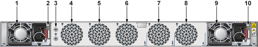
| 1 | Power supply 1 (PS1) | 6 | Fan 3 |
| 2 | PS1 LED | 7 | Fan 4 |
| 3 | Functional grounding point | 8 | Fan 5 |
| 4 | Fan 1 | 9 | Power supply 2 (PS2) |
| 5 | Fan 2 | 10 | PS2 LED |
The Arista 5510 Enterprise WAN router rear panel includes the following key components:
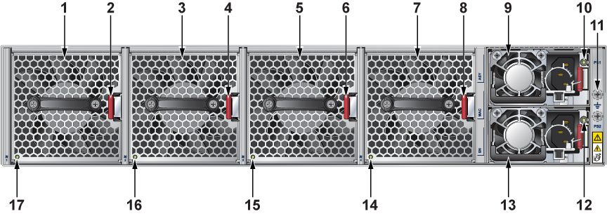
| 1 | Fan module 1 | 10 | PS1 LED |
| 2 | Fan module latch | 11 | Functional grounding point |
| 3 | Fan module 2 | 12 | PS2 LED |
| 4 | Fan module latch | 13 | Power supply 2 (PS2) |
| 5 | Fan module 3 | 14 | Fan status LED |
| 6 | Fan module latch | 15 | Fan status LED |
| 7 | Fan module 4 | 16 | Fan status LED |
| 8 | Fan module latch | 17 | Fan status LED |
| 9 | Power supply 1 (PS1) |
This section describes the front panel of the following routers:
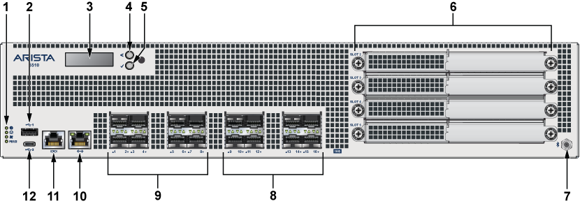
The Arista 5310 Enterprise WAN Router front panel includes the following key components:
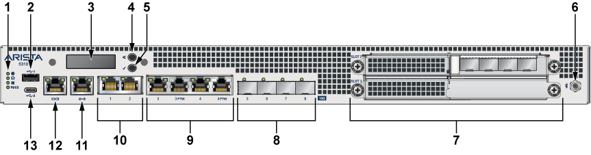
| 1 | System status LEDs | 8 | 4x10G SFP+ ports |
| 2 | USB port Type-A | 9 | 4x1G/10G RJ45 (2 ports support fail-to-wire (FTW)) |
| 3 | LCD panel | 10 | 2x1G/10G RJ45 |
| 4 | LCD upper button | 11 | RJ45 Ethernet management port |
| 5 | LCD lower button | 12 | RJ45 Console port |
| 6 | Bluetooth antenna (BT antenna) | 13 | USB port Type-C |
| 7 | 2x NIM (Network Interface Module) 3.0 slots |
The Arista 5510 Enterprise WAN Router front panel includes the following key components:
| 1 | System status LEDs | 7 | Bluetooth antenna (BT antenna) |
| 2 | USB port Type-A | 8 | 8xSFP+ 10G enhanced |
| 3 | LCD panel | 9 | 8xSFP+ 10G |
| 4 | LCD upper button | 10 | RJ45 Ethernet management port |
| 5 | LCD lower button | 11 | Console port |
| 6 | 4x NIM (Network Interface Module) 3.0 slots | 12 | USB port Type-C |
This section lists the default and optional installation parts of the accessory kit. Each router comes with an accessory kit that contains the necessary parts that are required to install the router.
The following accessories are available along with the router:
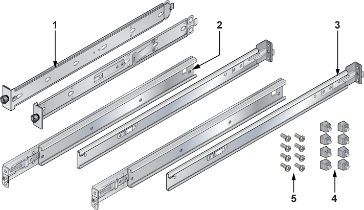
| 1 | Mounting bracket | 4 | Rack plugs |
| 2 | Rail slide | 5 | Screws (for fixing rack plugs to rail rod and rail slide) |
| 3 | Rail rod |
Cables
RJ45 Ethernet cable
Console cable
Power cable (country-specific, included only if specified before purchase)
The following are the SKU numbers and descriptions for the Arista 5000 series routers.
| SKU | Product Description |
|---|---|
| AWE-5310-2F-FLX | Arista 5310, router, up to 5Gbps IPsec-encrypted throughput, 1 RU, 8x RJ45 ports (w/2x port fail-to-wire), 4x 10G port SFP+, two expansion slots, two replaceable 550-watt power supplies, fixed fans, front-to-rear airflow. Includes FLX license. |
| AWE-5510-2F-FLX | Arista 5510, router, up to 50Gbps IPsec-encrypted throughput, 2 RU, 8x SFP+ 10G, 8x SFP+ 10G enhanced (Accelerated Cryptographic Processing), four expansion slots, two replaceable 800-watt power supplies, replaceable fans, front-to-rear airflow. Includes FLX license. |
Arista routers ship from the factory in Zero Touch Provisioning (ZTP) mode. ZTP configures the router without user intervention by downloading a startup configuration file or a boot script from a location specified by a DHCP server.
To manually configure an Arista router, bypass ZTP. The initial configuration provides one username (admin) accessible only through the console port because it does not have a password.
When bypassing ZTP, access the router by logging in as admin, with no password, through the console port. Then you can configure a password for the admin and other password-protected usernames.
The manual configuration procedure described below cancels ZTP mode, logs into the router, assigns a password to the admin, assigns an IP address to the management port, and defines a default route to a network gateway.
The device is in Zero Touch Provisioning mode and is attempting to
download the startup-config from a remote system. The device will not
be fully functional until either a valid startup-config is downloaded
from a remote system or Zero Touch Provisioning is cancelled. To cancel
Zero Touch Provisioning, login as admin and type 'zerotouch cancel'
at the CLI.
localhost login:
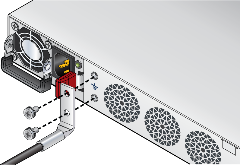
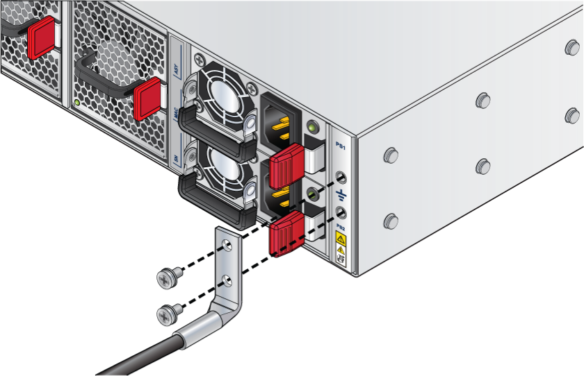
This section provides instructions for grounding the router.
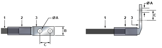
| 1 | Insulated cable | A | 1/4″ |
| 2 | Heat-shrink tubing | B | 1/2″ |
| 3 | Lug | C | 5/8″ |
Power cords for use outside of the United States must be ordered separately. Ensure that the power cord is compliant with local and national electrical codes.
Installation de cet équipement doit être conformes aux codes électriques locaux et nationaux. Si nécessaire, consulter les organismes de réglementation appropriés et des autorités de contrôle pour assurer la conformité.
Lire toutes les instructions d’installation avant de brancher le système à la source d’alimentation.
Cet équipement doit être mis à la terre. Ne jamais modifier le conducteur de terre.
Cet appareil requiert une protection contre les surintensités.
The following image displays an AC power supply, including the power socket on the left side of the module. The AC power supply connects to a circuit that provides the required power, as specified in the Specifications section.
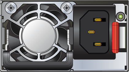
The power supplies require cables that comply with IEC-320 and have a C14 connector. The accessory kit provides two IEC-320 C13 to C14 power cables.
Table 1 - RJ45 to DB9 Connections lists the pin connections of the RJ45 to DB9 adapter cable.
|
RJ45 |
DB9 |
RJ45 |
DB9 |
|||||
|---|---|---|---|---|---|---|---|---|
| RTS | 1 | 8 | CTS | GND | 5 | 5 | GND | |
| DTR | 2 | 6 | DSR | RXD | 6 | 3 | TXD | |
| TXD | 3 | 2 | RXD | DSR | 7 | 4 | DTR | |
| GND | 4 | 5 | GND | CTS | 8 | 7 | RTS | |
Flexion excessive peut endommager les câbles d’interface.
This section describes the meaning of the front-panel LED status indicators.
| LED Name | LED State | LED Status |
|---|---|---|
| System Status LED | Off | No power or in the midst of a power cycle. |
| Blinking green | The system is powering up. | |
| Green | The system is operating in a normal initialization sequence. Normal operations. | |
| Blue | The locator function is active. | |
| Amber | The system is malfunctioning. The system is overheating, or temperature sensors have recorded passing the software-defined critical threshold.
The router will automatically execute a reboot/power cycle. |
|
| Cloud Connect Status LED | Off | The system not connected to CloudVision. |
| Green | The system is connected to CloudVision. | |
| Amber | There is a problem connecting to CloudVision. | |
| Fan Status LED | Green | All fan modules are operating normally. |
| Amber | The single fan module is malfunctioning. | |
| Power Supply Status LED | Off | The power supply unit is not available. |
| Green | The power supply unit is fully functional. | |
| Amber | The power supply unit has a fault. |