Ethernet Ports
Ethernet Ports introduction
Arista switches support a variety of Ethernet network interfaces. This chapter describes the configuration and monitoring options available in Arista switching platforms.
Ethernet Standards
Ethernet, standardized in IEEE 802.3, is a group of technologies used for communication over local area networks. Ethernet communication divides data streams into frames containing addresses (source and destination), payload, and Cyclical Redundancy Check (CRC) information.
IEEE 802.3 also describes two types of optical fiber: Single-Mode Fiber (SMF) and Multi-Mode Fiber (MMF). MMF range limits from 50 to 500 meters range.
100 Gigabit Ethernet
The 100 Gigabit Ethernet (100GbE) standard defines an Ethernet implementation with a nominal data rate of 100 billion bits per second over 10x10G, 4x25G, or 1x100G. 100 Gigabit Ethernet implements full duplex point-to-point links connected by network switches. Arista switches support 100GBASE-10SR through MXP ports.
40 Gigabit Ethernet
The 40 Gigabit Ethernet (40GbE) standard defines an Ethernet implementation with a nominal data rate of 40 billion bits per second over multiple 10 gigabit lanes. 40 Gigabit Ethernet implements full duplex point to point links connected by network switches. 40 Gigabit Ethernet standards use the “40GBASE-xyz" naming scheme, as explained in 40GBASE-xyz Interpretation.
| x | y | z |
|---|---|---|
| Non-fiber media type, or fiber wavelength | PHY encoding | Number of WWDM wavelengths or XAUI Lanes |
| C = Copper F = Serial SMF K = Backplane L = Long (1310 nm) S = Short (850 nm) | R = LAN PHY (64B/66B) | No value = 1 (serial) 4 = 4 WWDM wavelengths or XAUI Lanes |
10 Gigabit Ethernet
The 10 Gigabit Ethernet (10GbE) standard defines an Ethernet implementation with a nominal data rate of 10 billion bits per second. 10 Gigabit Ethernet implements full duplex point-to-point links connected by network switches. Half duplex operation, hubs, and CSMA/CD do not exist in 10GbE. The standard encompasses several PHY standards; a networking device may support different PHY types through pluggable PHY modules. 10GbE standards are named 10GBASE-xyz, as interpreted by 10GBASE-xyz Interpretation.
| x | y | z |
|---|---|---|
| media type or wavelength, if media type is fiber | PHY encoding type | Number of WWDM wavelengths or XAUI Lanes |
| C = Copper (twin axial) T = Twisted Pair S = Short (850 nm) L = Long (1310 nm) E = Extended (1550 nm) Z = Ultra extended (1550 nm) | R = LAN PHY (64B/66B) X = LAN PHY (8B/10B) W = WAN PHY(*) (64B/66B) | If omitted, value = 1 (serial) 4 = 4 WWDM wavelengths or XAUI Lanes |
Gigabit Ethernet
The Gigabit Ethernet (GbE) standard, defined by IEEE 802.3-2008, describes an Ethernet version with a nominal data rate of one billion bits per second. GbE cables and equipment are similar to those used in previous standards. While full-duplex links in switches are the typical implementation, the specification permits half-duplex links connected through hubs.
- 1000BASE-SX is a fiber optic standard that utilizes multi-mode fiber supporting 770 to 860 nm, near-infrared (NIR) light wavelength to transmit data over distances ranging from 220 to 550 meters. Network designs typically leverage 1000BASE-SX for intra-building links in large office buildings, co-location facilities, and carrier-neutral Internet exchanges.
- 1000BASE-LX is a fiber standard that utilizes a long wavelength laser (1,2701,355 nm) with an RMS spectral width of 4 nm to transmit data up to 5 km. 1000BASE-LX can run on all common types of multi-mode fiber with a maximum segment length of 550 m.
- 1000BASE-T is a standard for gigabit Ethernet over copper wiring. Each 1000BASE-T network segment can be a maximum length of 100 meters.
10/100/1000BASE-T
Arista switches provide 10/100/1000BASE-T Ethernet out-of-band management ports. Auto-negotiation is enabled on these interfaces. Speed (10/100/1000), duplex (half/full), and flow control settings are available using the appropriate speed and flowcontrol commands.
Power over Ethernet (PoE)
Selected Arista switches provide Power over Ethernet (PoE) to power connected devices. Arista’s PoE implementation is compliant with IEEE standards 802.3af and 802.3at and includes partial support for 802.3bt.
When a standards-compliant Powered Device (PD) is connected to a PoE-enabled Ethernet port, it is recognized by a specific resistor signature, and its power class is determined by hardware negotiation; more granular power adjustments can then be managed by the Link Layer Discovery Protocol (lldp).
Link Fault Signaling
Link Fault Signaling (LFS) is a mechanism by which a port transmits remote link fault signals to its peer over the link that is experiencing problems by configuring specific actions. LFS operates between the remote Reconciliation Sublayer (remote RS) and the local Reconciliation Sub-layer (local RS). The local RS treats faults detected between the remote RS and the local RS as local faults.
- Disable the error on the interface.
- Generate system log messages.
- Generate a link fault.
Ethernet Physical Layer
The Ethernet Physical Layer (PHY) includes hardware components connecting a switch's MAC layer to a transceiver, a cable, and ultimately to a peer link partner.
Data exist in digital form at the MAC layer. On the line side of the PHY, data exist as analog signals: light blips on optical fiber or voltage pulses on copper cable. Signals may be distorted while in transit and recovery may require signal processing. Ethernet physical layer components include a PHY and a transceiver.
PHYs
The PHY provides translation services between the MAC layer and the transceiver. It also helps to establish links between the local MAC layer and peer devices by detecting and signaling fault conditions. The PHY line-side interface receives Ethernet frames from the link partner as analog waveforms. The PHY uses signal processing to recover the encoded bits, then sends them to the MAC layer.
- Physical Medium Attachment (PMA): Framing, octet synchronization, scrambling/ sdescrambling.
- Physical Medium Dependent (PMD): Consists of the transceiver.
- Physical Coding Sublayer (PCS): Performs auto-negotiation and coding (8B/10B or 64B/66B).
The MAC sublayer of the PHY provides a logical connection between the MAC layer and the peer device by initializing, controlling, and managing the connection with the peer.
The PHY's system-side interface receives Ethernet frames transmitted by the switch as a sequence of digital bits. The PHY encodes them into a media-specific waveform for transmission through the line-side interface and transceiver to the link peer. This encoding may include signal processing, such as pre-distortion and forward error correction.
- 10 Gigabit Attachment Unit Interface (XAUI): Connects an Ethernet MAC to a 10 Gb/s PHY.
- Serial Gigabit Media Independent Attachment (SGMII): Connects an Ethernet MAC to a 1 Gb/s PHY.
Transceivers
- Optical transceivers convert the PHY signal into light pulses that are sent through optical fiber.
- Copper transceivers connect the PHY to twisted-pair copper cabling.
Arista Small Form-Factor Pluggable (SFP+) and Quad Small Form Factor Pluggable (QSFP+) modules and cables provide high-density, low-power Ethernet connectivity over fiber and copper media. Arista offers transceivers that span data rates, media types, and transmission distances.
Arista 10 Gigabit Ethernet SFP+ Modules
- 10GBASE-SR (Short Reach)
- Link length: maximum 300 meters over multi-mode fiber.
- Optical interoperability with 10GBASE-SRL.
- 10GBASE-SRL (Short Reach Lite)
- Link length: maximum 100 meters over multi-mode fiber.
- Optical interoperability with 10GBASE-SR.
- 10GBASE-LRL (Long Reach Lite)
- Link length: maximum 1 km over single-mode fiber.
- Optical interoperability with 10GBASE-LR (1 km maximum).
- 10GBASE-LR (Long Reach)
- Link length: maximum 10 km over single-mode fiber.
- Optical interoperability with 10GBASE-LRL (1 km maximum).
- 10GBASE-LRM (Long Reach Multi-mode)
- Link length: maximum 220 meters over multi-mode fiber (50 um and 62.5 um).
- 10GBASE-ER (Extended Reach)
- Link length: maximum 40 km over single-mode fiber.
- 10GBASE-ZR (Ultra-Extended Reach)
- Link length: maximum 80 km over single-mode fiber.
- 10GBASE-DWDM (Dense Wavelength Division
Multiplexing)
- Link length: maximum 80 km over single-mode fiber (40 color options).
- Tunable SFP+ Optics Module, Full C-Band 50 GHz ITU Grid, up to 80km over duplex SMF.
Arista 10 Gigabit Ethernet CR Cable Modules
- 10GBASE-CR SFP+ to SFP+ Cables
- Link lengths of 0.5, 1, 1.5, 2, 2.5, 3, 5, and 7 meters over twinax copper cable.
- Includes SFP+ connectors on both ends.
- 4 x 10GbE QSFP+ to 4 x SFP+ twinax copper
cables.
- Link lengths of 0.5, 1, 2, 3, and 5 meters over twinax copper cable.
Arista 25 Gigabit Ethernet Modules
- 25GBASE-CR SFP28 Cable
- Capable of 10G/25Gb/s speeds with link lengths of 1 to 5 meters.
- AOC-S-S-25G SFP28 to SFP28 25GbE Active
Optical Cable.
- Link lengths of 3 to 30 meters.
- SFP-25G-SR SFP28 Optics Module
- Link length of up to 70 m over OM3 MMF or 100 m over OM4 MMF.
- SFP-25G-LR SFP28 Optics Module
- Link length of up to 10 kilometers over duplex SMF.
Arista 40 Gigabit Ethernet QSFP+ Cables and Optics
- 40GBASE-SR4 QSFP+ Transceiver.
- Link length: maximum 100 meters over parallel OM3 or 150 meters over OM4 MMF.
- Optical interoperability with 40GBASE-XSR4 (maximum distance of 100/150 meters).
- 40GBASE-XSR4 QSFP+ Transceiver.
- Link length maximum 300 meters over parallel OM3 or 450 meters over OM4 MMF.
- Optical interoperability with 40GBASE-SR4 (maximum distance of 100/150 meters).
- 40GBASE-LR4 QSFP+.
- Link length: maximum 10 km over duplex single-mode fiber.
- 40GBASE-CR4 QSFP+ to QSFP+ twinax copper
cables.
- Link lengths of 1, 2, 3, 5, and 7 meters over twinax copper cable.
- 40GBASE-BIDI Bidirectional QSFP+ Optic.
- Link length: up to 100 meters over parallel OM3 or 150 meters over OM4 MMF.
- 40GBASE-UNIV QSFP+ Optic.
- Link length: up to 150 meters over duplex OM3/OM4 MMF and 500 meters over duplex SMF.
- 40GBASE-LRL QSFP+ Optic.
- Link length: up to 1 kilometer over duplex SMF.
- 40GBASE-PLRL4 QSFP+ Optic.
- Link length: up to 1 kilometer over parallel SMF (i.e., 4x10G LR up to 1 km).
- 40GBASE-PLR4 QSFP+ Optic
- Link length: up to 10 kilometers over parallel SMF (i.e., 4x10G LR up to 1 km).
- 40GBASE-ER QSFP+ Optic.
- Link length: up to 40 kilometers over duplex SMF.
Arista Gigabit Ethernet SFP Options
- 1000BASE-SX (Short Haul).
- Multi-mode fiber.
- Link length: up to 550 meters.
- 1000BASE-LX (Long Haul).
- Single-mode fiber.
- Link length: up to 10 km (single mode).
- 1000BASE-T (RJ-45 Copper).
- Category 5 cabling.
- Full duplex 1000 Mbps connectivity.
Arista 100 Gigabit Ethernet QSFP Modules
- 100GBASE-SR4 QSFP transceiver.
- Link length: up to 70 meters over parallel OM3 or 100 meters over OM4 multi-mode fiber.
- 100GBASE-SWDM4 QSFP transceiver.
- Link length: up to 70 meters over OM3 or 100 meters over OM4 duplex multi-mode fiber.
- 100GBASE-BIDI QSFP transceiver.
- Link length: up to 70 meters over OM3 or 100 meters over OM4 duplex multi-mode fiber.
- 100GBASE-PSM4 40G/100G dual speed QSFP Optics
Module.
- Link length: up to 500 meters over parallel single-mode fiber.
- 100GBASE-CWDM4 40G/100G dual speed QSFP Optics
Module.
- Link length: up to 2 km over duplex single-mode fiber.
- 100GBASE-LRL4 QSFP Optics Module.
- Link length: up to 2 km over duplex single-mode fiber.
- 100GBASE-LR4 QSFP Optics Module.
- Link length: up to 10 km over duplex single-mode fiber.
- 100GBASE-ERL4 QSFP Optics Module.
- Link length: up to 40 km over duplex single-mode fiber.
- 100GBASE-ZR4 QSFP Optics Module.
- Link length: up to 80 km over single-mode fiber.
- 100GBASE-CR4 QSFP to QSFP Twinax copper
cable.
- Link lengths of 1 to 5 meters.
- 100GBASE-CR4 QSFP to 4 x 25GbE SFP Twinax
copper cable.
- Link lengths of 1 to 5 meters.
Internal Ports
- 100/1000BASE-T (7048T-A).
- 100/1000/10GBASE-T (7050-T).
AOC Cables
- AOC-Q-Q-100G QSFP 100GbE Active Optical
Cable.
- Link lengths of 3 to 30 meters.
- AOC-Q-Q-40G QSFP+ to QSFP+ 40GbE Active
Optical Cable.
- Link lengths of 3 to 100 meters.
- AOC-S-S-25G SFP28 to SFP28 25GbE Active
Optical Cable.
- Link lengths of 3 to 30 meters.
400GBASE-ZR Transceivers
- Compliance with CMIS4.0/CMIS4.1 (CMIS5.0) and Coherent CMIS.
- Frequency tuning (100 GHz and 75 GHz grids).
- DOM monitoring, including VDM (Versatile Diagnostics Monitoring) pages, defined in CMIS4.0.
- Coherent alarms and faults, including pages, defined by Coherent CMIS.
- Configurable Tx output power.
- A separate command for shutting down the Tx output path for unidirectional mode.
- 1-second update of pre-FEC BER, OSNR, ESNR.
- 400GBASE-ZR transceiver with Open Forward Error Correction (O-FEC) (eos release 4.25.2F.)
- 4x100 Gb/s mode for the 400GBASE-ZR transceivers (eos release 4.25.2F).
- Override a transceiver slot’s maximum power limit (eos release 4.25.2F.)
Platform Compatibility
The 400GBASE-ZR transceiver is a power class 8 module with a power consumption of up to 20W, the highest power consumption among 400G transceivers.
In theory, every 400GBASE OSFP or QSFP-DD switch is qualified to host 400GBASE-ZR transceivers. However, the actual number of 400GBASE-ZR modules that can be used by a switch simultaneously may vary, depending on platform (modular vs. fixed) and ASIC type. It is always recommended to discuss the installation of 400GBASE-ZR modules with Arista support.
Using 400GBASE-ZR in Combination with OSFP-LS
Arista eos allows the use of OSFP-LS (pluggable line system in the OSFP form factor), instead of traditional DCI line systems.
Configuring 400GBASE-ZR Transceivers
Laser Frequency Configuration
switch# conf
switch(config)#
switch(config)# interface Ethernet12/1
switch(config-if-Et12/1)# transceiver frequency 193100
switch(config-if-Et12/1)#
Configured and operational frequency settings can be verified using the show interface transceiver hardware command.
- It can take up to 90 seconds for the 400GBASE-ZR module to fully complete frequency tuning.
- The frequency plan for 400GBASE-ZR modules support channel spacings of 100 GHz or 75 GHz. It is recommended to use operating frequency channel definitions in chapter 15 of [4].
Transmit Output Power Configuration
Programmable output power advertisement (04h:196-201):
    Lane programmable output power supported (04h:196): true
    Min programmable output power (04h:198-199): -14 dB
Max programmable output power (04h:200-201): -10 dBswitch# conf
switch(config)# interface Ethernet14/1
switch(config-if-Et14/1)# transceiver transmitter signal-power ?
switch(config-if-Et14/1)# transceiver transmitter signal-power -10You can check the configured TX power using the show interface transceiver hardware command and the actual operational TX power using the show interface transceiver command.
- 400GBASE-ZR does not have a recommended level of transmit laser power. In most cases, it is okay to keep the default power.
- Some vendors may not populate the range of supported output powers correctly. The range -10 to -14 dBm should be supported. Contact Arista Support if you are planning to configure the output power outside of this range.
Transmit Output Disable and Unidirectional Mode
switch# conf
switch(config)# interface Ethernet14/1
switch(config-if-Et14/1)# transceiver transmitter DISABLED
To re-enable the transmit path, use the no or default version of the above configuration command.
Configuring 4x100 Gb/s mode for 400GBASE-ZR transceivers
switch(config-if-Et4/1)# speed 100g-2
switch(config-if-Et4/3,4/5,4/7)# speed 100g-2

switch# show interfaces ethernet 4/1-5/8 status
Port   	Name   Status   	  Vlan 	Duplex Speed  Type     	Flags Encapsulation
Et4/1       	  connected 	  1    	full   100G   400GBASE-ZR
Et4/3       	  connected 	  1    	full   100G   400GBASE-ZR
Et4/5       	  connected 	  1    	full   100G   400GBASE-ZR
Et4/7       	  connected 	  1    	full   100G   400GBASE-ZR
Et5/1       	  connected          1    	full   100G   400GBASE-ZR
Et5/3       	  connected          1    	full   100G   400GBASE-ZR
Et5/5       	  connected          1    	full   100G   400GBASE-ZR
Et5/7 connected 1 full 100G 400GBASE-ZRswitch(config-if-Et4/1,4/3,4/5)# shutdown
switch# show interfaces ethernet 4/1-5/8 status
Port Name Status Vlan Duplex Speed Type Flags Encapsulation
Et4/1 disabled 1 full 100G 400GBASE-ZR
Et4/3 disabled 1 full 100G 400GBASE-ZR
Et4/5 disabled 1 full 100G 400GBASE-ZR
Et4/7 connected 1 full 100G 400GBASE-ZR
Et5/1 notconnect 1 full 100G 400GBASE-ZR
Et5/3 notconnect 1 full 100G 400GBASE-ZR
Et5/5 notconnect 1 full 100G 400GBASE-ZR
Et5/7 connected 1 full 100G 400GBASE-ZR
switch# show interfaces ethernet 4/1 transceiver
If device is externally calibrated, only calibrated values are printed.
N/A: not applicable, Tx: transmit, Rx: receive.
mA: milliamperes, dBm: decibels (milliwatts).
Bias Optical Optical
Temp Voltage Current Tx Power Rx Power
Port (Celsius) (Volts) (mA) (dBm) (dBm) Last Update
----- --------- -------- -------- -------- -------- -------------------
Et4/1 59.00 3.25 279.70 -9.46 -8.29 0:00:01 agoswitch(config-if-Et4/7)# shutdown
switch# show interfaces ethernet 4/1-5/8 status
Port Name Status Vlan Duplex Speed Type Flags Encapsulation
Et4/1 disabled 1 full 100G 400GBASE-ZR
Et4/3 disabled 1 full 100G 400GBASE-ZR
Et4/5 disabled 1 full 100G 400GBASE-ZR
Et4/7 disabled 1 full 100G 400GBASE-ZR
Et5/1 notconnect 1 full 100G 400GBASE-ZR
Et5/3 notconnect 1 full 100G 400GBASE-ZR
Et5/5 notconnect 1 full 100G 400GBASE-ZR
Et5/7 notconnect 1 full 100G 400GBASE-ZR
switch# show interfaces ethernet 4/1 transceiver
If device is externally calibrated, only calibrated values are printed.
N/A: not applicable, Tx: transmit, Rx: receive.
mA: milliamperes, dBm: decibels (milliwatts).
Bias Optical Optical
Temp Voltage Current Tx Power Rx Power
Port (Celsius) (Volts) (mA) (dBm) (dBm) Last Update
----- --------- -------- -------- -------- -------- -------------------
Et4/1 44.00 3.33 0.00 -30.00 -30.00 0:00:01 agoConfiguring Open Forward Error Correction on 400GBASE-ZR
Open FEC (O-FEC) is a Forward Error Correction encoder and decoder, specified in the Open ZR+ MSA [2], with an overhead of 15.3% and a net coding gain of 11.6 dB for 16QAM modulation. Compared to Concatenated FEC (C-FEC), which is a default FEC specified for 400GBASE-ZR coherent transceivers by CMIS4.0, O-FEC provides higher coding gain (11.6dB for O-FEC vs 10.8 dB for C-FEC /16QAM), and it can correct a pre-FEC BER of up to 2E-2.
switch(config-if-Et4/1)# error-correction encoding openTransceiver Slot’s Maximum Power Limit
switch(config-if-Et4/1)# transceiver power ignore
! You can risk damaging hardware by using transceiver modules with high power consumption. We recommend that you do this only under direction from Arista Networks.
Show Commands
- show interface transceiver eeprom
The show interface transceiver eeprom command displays the parsed capabilities.
Example
For 400GBASE-ZR, the display of frequency tuning, power tuning (page 04h), and VDM configuration pages (20h-23h) is added.switch# show interface Ethernet15/1 transceiver eeprom Ethernet15 EEPROM: ... Frequency tuning support (04h:128-129): Grid spacing capabilities (04h:128): 100 GHz grid supported (04h:128): true 12.5 GHz grid supported (04h:128): false 25 GHz grid supported (04h:128): false 3.125 GHz grid supported (04h:128): false 33 GHz grid supported (04h:128): false 50 GHz grid supported (04h:128): false 6.25 GHz grid supported (04h:128): false 75 GHz grid supported (04h:128): true Tunable wavelength (04h:128): true Fine tuning support (04h:129): false Supported channel boundaries (04h:130-161): 100 GHz grid (04h:150-153): Lowest channel (04h:150-151): -18 Lowest frequency (04h:150-151): 191300000 MHz Highest channel (04h:152-153): 30 Highest frequency (04h:152-153): 196100000 MHz 75 GHz grid (04h:158-161): Lowest channel (04h:158-159): -72 Lowest frequency (04h:158-159): 191300000 MHz Highest channel (04h:160-161): 120 Highest frequency (04h:160-161): 196100000 MHz Programmable output power advertisement (04h:196-201): Lane programmable output power supported (04h:196): false VDM configuration (20h:128-255;21h:128-255): VDM group 1 (20h:128-255): Parameter 1 (20h:128-129): Lane (20h:128): 0 Threshold ID (20h:128): 0 Parameter type (20h:129): Laser temperature Parameter 3 (20h:132-133): Lane (20h:132): 0 Threshold ID (20h:132): 2 Parameter type (20h:133): eSNR host input Parameter 4 (20h:134-135): Lane (20h:134): 1 Threshold ID (20h:134): 2 Parameter type (20h:135): eSNR host input Parameter 5 (20h:136-137): Lane (20h:136): 2 Threshold ID (20h:136): 2 Parameter type (20h:137): eSNR host input ... Parameter 84 (21h:166-167): Lane (21h:166): 0 Threshold ID (21h:166): 14 Parameter type (21h:167): MER Number of VDM groups supported (2Fh:128): 2 - show interface transceiver dom
The show interface transceiver dom command displays the most important current performance data on the media (line) side.
Exampleswitch# show interface Ethernet11/1 transceiver dom Ch: Channel, N/A: not applicable, TX: transmit, RX: receive mA: milliamperes, dBm: decibels (milliwatts), C: Celsius, V: Volts Port 11 Last update: 0:00:05 ago Value ---------------- Case temperature 66.59 C Voltage 3.26 V TX power -10.23 dBm RX total power -11.61 dBm RX channel power -11.94 dBm Pre-FEC BER 1.82e-03 Post-FEC errored frames ratio 0.00e+00 Chromatic dispersion (short link) 0.00 ps/nm Chromatic dispersion (long link) 0.00 ps/nm Differential group delay 9.31 ps SOPMD 0.00 ps^2 Polarization dependent loss 0.40 dB Received OSNR estimate 35.10 dB Received ESNR estimate 17.50 dB Carrier frequency offset 0.00 MHz Error vector magnitude 100.00 % SOP rate of change 0.00 krad/s Laser temperature 59.54 C Laser frequency 193100.00 GHz- BER: Bit Error Rate
- FEC: Forward Error Correction
- OSNR: Optical Signal to Noise Ratio
- ESNR: Electrical Signal to Noise Ratio
- SOP: State of Polarization
- SOPMD: State of Polarization Mode Dispersion
- show interfaces hardware
The show interfaces hardware command displays the speed capabilities of a module. A 400GBASE-ZR supports 4x100 Gb/s mode if the 100G-2/full speed is supported.
Example
switch# show interfaces ethernet 4/1 hardware * = Requires speed group setting change Ethernet4/1 Model: DCS-7280PR3K-24 Type: 400GBASE-ZR Speed/duplex: 100G-2/full,400G-8/full(default) Flowcontrol: rx-(off,on),tx-(off) Modulation: 16QAM Error correction: C-FEC(16QAM(default)), O-FEC(16QAM)The show interface status command displays the status and characteristics of the Ethernet interfaces:
switch#show interfaces ethernet 4/1,4/3,4/5,4/7 status Port Name Status Vlan Duplex Speed Type Flags Encapsulation Et4/1 connected 1 full 100G 400GBASE-ZR Et4/3 connected 1 full 100G 400GBASE-ZR Et4/5 connected 1 full 100G 400GBASE-ZR Et4/7 connected 1 full 100G 400GBASE-ZR - show transceiver status interface
The show transceiver status interface command displays the most important alarms, faults,interface statuses, and the existence of four host interfaces in the example below.
Example
For 400GBASE-ZR modules, media and host-side coherent alarms, host-side pre-FEC BER (defined in the Coherent CMIS), and post-FEC BER have been added to the command’s output:switch# show transceiver status interface Ethernet 4/1,4/3,4/5,4/7 Current State Changes Last Change ------------- ------- ----------- Port 4 Transceiver 400GBASE-ZR 3 2:32:34 ago Transceiver SN 204653947 Presence present Adapters none Bad EEPROM checksums 0 never Resets 0 2:32:41 ago Interrupts 0 never Data path firmware fault ok 0 never Module firmware fault ok 0 never Temperature high alarm ok 0 never Temperature high warn ok 0 never Temperature low alarm ok 0 never Temperature low warn ok 0 never Voltage high alarm ok 0 never Voltage high warn ok 0 never Voltage low alarm ok 2 2:32:19 ago Voltage low warn ok 2 2:32:19 ago Module state ready 6 0:02:21 ago Data path 1 state activated 12 0:01:33 ago Data path 2 state activated 12 0:01:33 ago Data path 3 state activated 12 0:01:33 ago Data path 4 state activated 12 0:01:33 ago Data path 5 state activated 12 0:01:33 ago Data path 6 state activated 12 0:01:33 ago Data path 7 state activated 12 0:01:33 ago Data path 8 state activated 12 0:01:33 ago RX LOS ok 4 0:01:33 ago TX fault ok 0 never RX CDR LOL ok 4 0:01:31 ago TX power high alarm ok 0 never TX power high warn ok 4 0:02:12 ago TX power low alarm ok 4 0:02:21 ago TX power low warn ok 6 0:02:12 ago TX bias high alarm ok 0 never TX bias high warn ok 0 never TX bias low alarm ok 0 never TX bias low warn ok 0 never RX power high alarm ok 0 never RX power high warn ok 0 never RX power low alarm ok 0 never RX power low warn ok 0 never TX loss of alignment ok 0 never TX out of alignment ok 0 never TX clock monitor unit LOL ok 0 never TX reference clock LOL ok 0 never TX deskew LOL ok 0 never TX FIFO error ok 0 never RX demodulator LOL ok 4 0:01:30 ago RX CD compensation LOL ok 4 0:01:30 ago RX loss of alignment ok 0 never RX out of alignment ok 0 never RX deskew LOL ok 0 never RX FIFO error ok 0 never RX FEC excessive degrade ok 0 never RX FEC detected degrade ok 0 never Freq tuning in progress idle 8 0:01:32 ago Freq tuning busy ok 0 never Freq tuning invalid channel ok 0 never Freq tuning completed no 8 0:01:30 ago Ethernet4/1 Operational speed 100Gbps Pre-FEC bit error rate 0.00e+00 Post-FEC errored frames ratio 0.00e+00 TX LOS Host lane 1 ok 2 0:02:21 ago Host lane 2 ok 2 0:02:21 ago TX CDR LOL Host lane 1 ok 2 0:02:21 ago Host lane 2 ok 0 never TX adaptive input EQ fault Host lane 1 ok 2 0:02:21 ago Host lane 2 ok 2 0:02:21 ago Ethernet4/3 Operational speed 100Gbps Pre-FEC bit error rate 0.00e+00 Post-FEC errored frames ratio 0.00e+00 TX LOS Host lane 3 ok 2 0:02:21 ago Host lane 4 ok 2 0:02:21 ago TX CDR LOL Host lane 3 ok 2 0:02:21 ago Host lane 4 ok 2 0:02:21 ago TX adaptive input EQ fault Host lane 3 ok 2 0:02:21 ago Host lane 4 ok 2 0:02:21 ago Ethernet4/5 Operational speed 100Gbps Pre-FEC bit error rate 0.00e+00 Post-FEC errored frames ratio 0.00e+00 TX LOS Host lane 5 ok 2 0:02:21 ago Host lane 6 ok 2 0:02:21 ago TX CDR LOL Host lane 5 ok 0 never Host lane 6 ok 2 0:02:21 ago TX adaptive input EQ fault Host lane 5 ok 0 never Host lane 6 ok 2 0:02:21 ago Ethernet4/7 Operational speed 100Gbps Pre-FEC bit error rate 0.00e+00 Post-FEC errored frames ratio 0.00e+00 TX LOS Host lane 7 ok 2 0:02:21 ago Host lane 8 ok 2 0:02:21 ago TX CDR LOL Host lane 7 ok 2 0:02:21 ago Host lane 8 ok 2 0:02:21 ago TX adaptive input EQ fault Host lane 7 ok 2 0:02:21 ago Host lane 8 ok 0 never - Wavelength/Frequency and Output Power StatusThe show interface transceiver hardware command displays the configured and programmed wavelength and output power. It takes a short time for the configured wavelength or output power to be programmed into the transceiver. The configured wavelength/output power and programmed wavelength/output power should not differ for an extended period of time.
switch# show interface Ethernet23/1 trans hardware Name: Et23/1 Media type: 400GBASE-ZR Maximum module power (W): 20.0 Maximum slot power (W): 20.0 Configured frequency (GHz): 193100.0 Computed wavelength (nm): 1552.52 Operational frequency (GHz): 193,100.0 Operational wavelength (nm): 1552.52 Configured TX power (dBm): -10.0 Operational TX power (dBm): -10.0Note: Configured transmit output power and operational transmit output power are only displayed if configurable output power is supported by the module.
Troubleshooting
- Check the transceiver type: make sure it is 400GBASE-ZR.
- Check the peer transceiver: make sure it is also 400GBASE-ZR.
- Check that the channel/frequency is configured and the interfaces are not in error-disabled state.
- Check that the selected frequency is matching on both sides of the optical link.
- Check that transmit output is not disabled.
- If the TX power is not configured, check that it is from -6 dB to -12 dB.
- If the TX power is configured, check that it matches its configured values on both sides of the optical link.
- Check the RX power. The best performance of an optical link is achieved when the received power is -10dB.
- Collect the output of the CLI commands listed in the “Show commands” section before requesting support from the development team.
- Check that the pre-FEC BER (show transceiver dom command) is in the correct range (less than 1E-2).
- In the show transceiver status interface output, check that the module state is Ready and that data path state is Activated. Check for possible alarms and faults.
Link Issues
If a link has issues, the following commands and files are useful for debugging and for Arista TAC.
- show interfaces <interfaceName> phy detail.
- show interfaces <interfaceName> transceiver detail.
- show idprom transceiver <interfaceName> ext.
- Files in /var/log/agents/*.
- Files in /var/log/qt/*.
- /var/log/messages*.
Limitations
MXP Ports
- The 100GbE mode requires an MTP-24 to MTP-24 cable, which uses 20 of 24 fibers to carry 100GbE across 10 send and 10 receive channels. When connecting two 100GbE MXP ports, the TX lanes must be crossed with the RX lanes.
- The 40GbE mode requires an MTP cable that provides a split into three MTP-12 ends. The cable splits the MXP port into three MTP-12 ends, each compatible with standard-based 40GBASE-SR4 ports over OM3 or OM4 fiber up to a 100 m or 150 m distance.
- The 10GbE mode requires an MTP cable that provides a split into 12x10GbE links with LC connectors to adapt the MXP port into 12x10GbE ports. The cable splits the MXP port into twelve LC ends to connect to SR or SRL optics over multi-mode OM3/OM4 cables.
Interfaces
Arista switches provide two physical interface types that receive, process, and transmit Ethernet frames: Ethernet interfaces and Management interfaces.
Each Ethernet interface is assigned a 48-bit MAC address and communicates with other interfaces by exchanging data packets. Each packet contains the MAC address of its source and destination interface. Ethernet interfaces establish link level connections by exchanging packets. Interfaces do not typically accept packets with a destination address of a different interface.
Ethernet data packets are frames. A frame begins with preamble and start fields, followed by an Ethernet header that includes source and destination MAC addresses. The middle section contains payload data, including headers for other protocols carried in the frame. The frame ends with a 32-bit Cyclic Redundancy Check (CRC) field that interfaces use to detect data corrupted during transmission.
Ethernet Interfaces
- 40GbE, OSFP, QSFP+, QSFP-DD, and QSFP200: Default operation is as four 10GbE ports. The speed command options support the configuration as a single 40GbE port.
- 1000BASE-T / 2.5GBASE-T / 5GBASE-T / 10GBASE-T (copper): The default configuration enables the Clause 28 auto-negotiation feature for the port to negotiate the speed based on the peer’s capabilities. Depending on the individual SKU’s capabilities, these ports support 10 Mbps, 100 Mbps, 1 Gbps, 2.5 Gbps, 5 Gbps, and 10 Gbps rates and half/full-duplex mode of operation. The speed auto speed_value command limits the port advertisements to a specific speed. The speed speed_value command disables the Clause 28 auto-negotiation and uses the specified speed as the forced speed setting.
- 10GBASE-T (SFP+): The port operates as a single 10GbE port. The speed command does not affect the configuration.
- 100GbE CFP2: It operates at 100 Gb/s speed. You cannot split the interface or change its speed.
- 100GbE MXP: Operates as three 40GbE ports on the 7050 platform. The available speed/duplex settings are: three 40GbE ports or twelve 10GbE ports. You can make adjustments with the speed command.
- 100GbE QSFP100: Available speeds are transceiver-dependent. The QSFP100 transceiver supports a single 100GbE port, four 25GbE ports, or two 50GbE ports; the QSFP+ transceiver supports one 40GbE port or four 10GbE ports; the CWDM transceiver supports all five configurations. You can make adjustments with the speed command.
- The 1000BASE-T SFP transceivers
advertise one speed at a time only. Hence, the desired speed must be configured explicitly
using one of the following commands:
- speed auto: auto-negotiates the 1 Gbps speed (this is because no speed is specified, defaulting to advertise 1 Gbps).
- speed auto 1Gfull / speed auto: auto-negotiate the 1 Gbps speed (note that per the 1000BASE-T standard, 1 Gbps must be negotiated).
- speed auto 100full: auto-negotiates the 100 Mbps speed.
- speed 100full: forces the non-negotiated 100 Mbps speed.
- The 10GBASE-T SFP transceivers advertise one speed at a time only, similarly to how 1000BASE-T SFPs operate, unlike native BASE-T ports. The no speed and default speed commands configure the PHY to advertise only 10 Gbps.
For information relating to transceivers, see Transceivers.
Subinterfaces
Subinterfaces divide a single Ethernet port or a port channel interface into multiple logical Layer 3 interfaces based on the 802.1Q tag (VLAN ID) of incoming traffic. Subinterfaces are commonly used in a device at the boundary between L2 and L3 domains, but they can also be used to isolate 802.1Q-tagged traffic between L3 peers by assigning each subinterface to a different VRF.
- An L3 interface with subinterfaces configured on it should not be made a member of a port channel
- An interface that is a member of a port channel should not have subinterfaces configured
- A subinterface cannot be made a member of a port channel
Subinterfaces on multiple ports can be assigned the same VLAN ID, but there is no bridging between subinterfaces (or between subinterfaces and SVIs) as each subinterface is associated with a separate bridge domain.
- Unicast and multicast routing
- BGP, OSPF, ISIS, PIM
- ACL
- VRF
- VRRP
- SNMP
- Subinterface counters (on some platforms)
- VXLAN (on some platforms)
- MPLS (on some platforms)
- GRE (on some platforms)
- PBR (on some platforms)
- QoS (on some platforms)
- Inheriting QoS settings (trust mode and default DSCP) from the parent interface
- Inheriting MTU setting from parent interface
- Per-subinterface MTU setting
- Per-subinterface SFLOW settings
- Per-subinterface mirroring settings
Shared Shaper across Multiple Subinterfaces
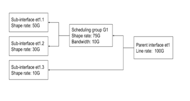
Sub-interfaces can be grouped into logical units called scheduling groups, which are shaped as a single unit. Each scheduling group may be assigned a scheduling policy which defines a shape rate in kbps and optionally a guaranteed bandwidth, also in kbps.
The guaranteed bandwidth is used if the sum of the shape rates of all scheduling groups and sub-interfaces that are not part of groups for a parent interface exceeds the available bandwidth. Each sub-interface within that scheduling group may have its own independent shape rate which are applied in a hierarchical manner.
Adding a sub-interface to a scheduling group results in allocation of dedicated Virtual Output Queues (VOQ) for the sub-interface.
Configuring Shared Shaper
- First, configure one or more sub-interfaces.
- Then, create a scheduling policy with the desired shape
rate and optional guaranteed
bandwidth:
switch(config)# qos scheduling switch(config-qos-scheduling)# scheduling policy P1 switch(config-qos-scheduling-policy-P1)# shape rate 75000000 switch(config-qos-scheduling-policy-P1)# bandwidth guaranteed 10000000 - The shape rate and guaranteed bandwidth may also be
defined as percents of the next highest level of
the hierarchy (in this case line
rate):
switch(config-qos-scheduling-policy-P1)# shape rate 75 percent switch(config-qos-scheduling-policy-P1)# bandwidth guaranteed percent 10 - Create the scheduling group on the parent
interface:
switch(config)# qos scheduling switch(config-qos-scheduling)# interface et1 switch(config-qos-scheduling-intf-Ethernet1)# scheduling group G1 - Assign a policy to the scheduling
group:
switch(config-qos-scheduling-intf-Ethernet1-group-G1)# policy P1 - Assign members to the scheduling group (members may be
put all on one line or on separate
lines):
switch(config-qos-scheduling-intf-Ethernet1-group-G1)# members et1.1 et1.2
Show Commands
- QoS configuration on one or more scheduling groups. Both group name and parent interface
name are optional, in which case all groups are displayed as shown in the example
below:
Example
switch# show qos scheduling group G1 Ethernet1 Interface: Et1 Scheduling Group Name: G1 Bandwidth: 10.1 / 10.0 (Gbps) Shape Rate: 75.2 / 75.0 (Gbps) Member Bandwidth Shape Rate (units) (units) ------ ------------- ------------------ Et1.1 - / - (-) 50.1 / 50.0 (Gbps) Et1.2 - / - (-) 30.1 / 30.0 (Gbps) - QOS configuration on a parent interface will show scheduling groups configured on the
parent
interface.
Example
switch# show qos interface Ethernet1 Ethernet1: Trust Mode: DSCP Default COS: 0 Default DSCP: 0 Port shaping rate: disabled Scheduling Group Bandwidth Shape Rate (units) (units) ---------------- ------------------ ------------------ G1 10.1 / 10.0 (Gbps) 75.1 / 75.0 (Gbps) - The entire scheduling hierarchy for a subinterface can be displayed. This displays the
shape rate for each transmit queue and then the shape rate and guaranteed bandwidth at every
other level of the
hierarchy.
Example
switch# show qos scheduling hierarchy Ethernet1.1 Interface Hierarchy Level Bandwidth Shape Rate (units) (units) --------- ------------------------- ------------------ ---------------- Et1/1.100 tx queue (0) - / - 100 / 100 (Mbps) tx queue (2) - / - 200 / 200 (Mbps) subinterface (Et1/1.1) 100 / 100 (Mbps) 500 / 500 (Mbps) group (G1) 10 / 10 (Gbps) 75 / 75 (Gbps) parent (Et1/1) (100 Gbps) - / - - / - ( - )
Agile Ports
Agile ports are a feature of the 7150S series that allows the user to configure blocks of 4 adjacent SFP+ interfaces as a single 40GbE link. The hardware configuration restricts the set of interfaces that can be combined to form a higher speed port: only interfaces that pass through a common PHY component can be combined.
One interface within a combinable set is designated as the primary port. When the primary interface is configured as a higher speed port, all configuration tasks are performed on that interface. All other interfaces in the set are subordinated to the primary interface and are notindividually configurable when the primary interface is configured as the higher speed port. This feature allows the 7150S-24 to behave as a 4x40GbE switch (using 16 SFP+ modules) while the remaining SFP+ modules provide eight 10GbE ports. On the 7150S-52 this capability supports up to 13 40GbE ports (all 52 ports configured in groups of four, each running at 40 Gb/s speed) and on the 7150S-64 agile ports enable the switch to be deployed with up to 16 40GbE interfaces: four are native QSFP+ ports while the remaining 12 are configured as 4xSFP+ groups.
Management Interfaces
A management interface is a Layer 3 host port that is typically connected to a management station for performing out-of-band switch management tasks. Each switch has one or two management interfaces. Only one port needs to manage the switch; the second port, when available, provides redundancy.
Management interfaces are 10/100/1000 BASE-T interfaces. By default, auto-negotiation is enabled on management interfaces. All combinations of 10/100/1000 speeds and full or half duplex are enforceable on these interfaces through the speed command.
Management ports are enabled by default. The switch cannot route packets between management ports and network ports because they are in separate routing domains. When the management station is multiple hops from the management port, packet exchanges through Layer 3 devices between the management port and management station may require the enabling of routing protocols.
The Ethernet management ports can be accessed remotely over a common network or locally through a directly connected computer. An IP address and a static route to the default gateway must be configured to be able to access the switch through a remote connection.
Tunable SFP Modules
- Tuning the transceiver wavelength/frequency by channel number.
- Showing the wavelengths/frequencies for specified channels supported by the transceiver.
- Showing the current wavelength/frequency settings of the transceiver interface.
For information about tuning the transceiver wavelength/frequency by channel number, refer to the command transceiver channel. To show the current wavelength/frequency settings for specified channels, refer to the command show interfaces transceiver channels. To show the current wavelength/frequency settings of an interface, refer to the command show interfaces transceiver hardware.
MRU Enforcement
Configuring MRU Enforcement
MRU is configurable per-interface, and can be configured on Ethernet and Port-Channel interfaces. Frames with size greater than the configured MRU value drop on the ingress, and do not forward to the destined egress interface. MRU enforcement happens at the Ethernet interface and applies to both L2 and L3 traffic. Note that FCS (frame check sequence) is included in the frame size.
Ethernet Interface
switch(config)# interface ethernet 1
switch(config)# l2 mru 9000Frames with size greater than 9000 bytes ingressing into Ethernet1 are dropped.
Port-Channel Interface
switch(config)# interface ethernet 1 - 4
switch(config-if-Et1-4)# channel-group 10 mode active
switch(config)# interface port-Channel 10
switch(config-if-Po10)#Frames with size greater than 9000 bytes ingressing into Ethernet1, 2, 3, and 4 are dropped.
Sub-interfaces
MRU configured on an Ethernet interface or Port-Channel are applied to all of its sub-interfaces.
Default Behaviours
- For DCS-7280R3 and DCS-7500R3 series.
- The maximum MRU is 10240 bytes.
- For other supported platforms
- In TapAgg mode, the maximum MRU is 10240 bytes.
- In non TapAgg mode, the maximum MRU is 10200 bytes.
MRU Enforcement Show Commands
The show interface output displays the MRU on an interface.
switch(config)# show interface ethernet 1
Ethernet1 is up, line protocol is up (connected)
Hardware is Ethernet, address is 444c.a8b7.1ed8 (bia 444c.a8b7.1ed8)
Member of Port-Channel10
Ethernet MTU 10178 bytes, Ethernet MRU 1500 bytes, BW 10000000 kbit
Full-duplex, 10Gb/s, auto negotiation: off, uni-link: disabled.Counters
MRU-dropped packets are counted per-chip.
switch(config)# show platform fap mapping interface Ethernet 1
Jericho0 (FapId: 0 BaseSystemCoreId: 0)
Port SysPhyPort Voq Core FapPort OtmPort BaseQPair QPairs Xlge NifPort
----------------------------------------------------------------------------------------
Ethernet1 100 2608 0 2 0 0 8 8 33switch(config)# show hardware counter drop
Type Chip CounterName : Count : First Occurrence : Last Occurrence
-----------------------------------------------------------------------------------------
A Jericho0 ReassemblyErrors : 12132989 : 2020-09-22 17:05:45 : 2020-09-22 17:22:40Displaying Interface Interactions
The show interfaces interactions command provides a resource that explains various relationships between Ethernet interfaces. It describes interactions in which a configuration on an interface causes another set of interfaces to become inactive or have reduced capabilities. Examples include a primary interface consuming subordinate interfaces to service four-lane speed or platform restrictions that require four interfaces to operate at the same speed.
No Interactions
- If all specified interfaces have no interactions, print at the first indentation level.
- If only some specified interfaces have no interactions and those interfaces have no interactions at any speeds, print at the second indentation level for those interfaces.
- If only some specified interfaces have no interactions and those interfaces only have interactions at some speeds, print at the third indentation level for those speeds.
switch# show int et1,2 interactions
No interfaces interactions
switch# show int et1,2,5/1 interactions
* = includes less than 10G speeds that the interface is capable of
Ethernet1
No interactions with other interfaces
Ethernet2
No interactions with other interfaces
Ethernet5/1
For speed 40G
Ethernet5/2-4 become inactive
For speed 10G*
No interactions with other interfacesInactive Interfaces
switch# show interfaces et11/1,11/3 interactions
* = includes less than 10G speeds that the interface is capable of
Ethernet11/1:
For speed 100G-4
Ethernet11/2-4 become inactive
For speed 50G-2
Ethernet11/2,11/4 become inactive
Ethernet11/3 is limited to 50G-2
For speed 40G
Ethernet11/2-4 become inactive
For speed 25G
Ethernet11/2-4 are limited to 25G
For speed 10G*
Ethernet11/2-4 are limited to 10G*
Ethernet11/3:
For speed 50G-2
Ethernet11/4 becomes inactive
Primary interface Ethernet11/1 must be operating at 50G-2
For speed 25G
Primary interface Ethernet11/1 must be operating at 25G
For speed 10G*
Primary interface Ethernet11/1 must be operating at 10G*Required Primary Interface Configuration
switch#show interfaces et11/1,11/3 interactions
* = includes less than 10G speeds that the interface is capable of
Ethernet11/1:
For speed 100G-4
Ethernet11/2-4 become inactive
For speed 50G-2
Ethernet11/2,11/4 become inactive
Ethernet11/3 is limited to 50G-2
For speed 40G
Ethernet11/2-4 become inactive
For speed 25G
Ethernet11/2-4 are limited to 25G
For speed 10G*
Ethernet11/2-4 are limited to 10G*
Ethernet11/3:
For speed 50G-2
Ethernet11/4 becomes inactive
Primary interface Ethernet11/1 must be operating at 50G-2
For speed 25G
Primary interface Ethernet11/1 must be operating at 25G
For speed 10G*
Primary interface Ethernet11/1 must be operating at 10G*Hardware Speed-Group Requirements
Some interface configurations require an additional speed-group configuration to operate correctly. If speed-group configurations are required, a message is displayed similar to the ones bolded below.
switch# show interfaces et1/1,2/1 interactions* = includes less than 10G speeds that the interface is capable of
Ethernet1/1:
For speed 100G-4
Ethernet1/2-4 become inactive
Hardware speed-group 1 must include 50g
For speed 40G
Ethernet1/2-4 become inactive
Hardware speed-group 1 must include 10g
For speed 25G
Ethernet2/1,2/3 become inactive
Ethernet1/3 is limited to 25G/10G
Hardware speed-group 1 must include 25g
For speed 10G
Ethernet2/1,2/3 become inactive
Ethernet1/3 is limited to 25G/10G
Hardware speed-group 1 must include 10g
Ethernet2/1:
For speed 100G-4
Ethernet2/3 becomes inactive
Ethernet1/1 must be operating at 100G-4/50G-2/40G
Hardware speed-group 1 must include 50g
For speed 40G
Ethernet2/3 becomes inactive
Ethernet1/1 must be operating at 100G-4/50G-2/40G
Hardware speed-group 1 must include 10gCompatible Parent Interface Configuration
The parent interface may be configured to any one of the compatible rates on the list. Additionally, more than one interface may be required to be configured at a compatible rate. These interactions are captured with messages similar to the ones bolded below
switch# show interfaces et1/1,1/8 interactions
* = includes less than 10G speeds that the interface is capable of
Ethernet1/1:
Ethernet1/1-4/8 share 18 interface hardware resources
For speed 400G-8
Ethernet1/2-8 become inactive
Hardware speed-group 1 must include 50g
For speed 200G-4
Ethernet1/2-4 become inactive
Hardware speed-group 1 must include 50g
For speed 100G-2
Ethernet1/2 becomes inactive
Hardware speed-group 1 must include 50g
For speed 100G-4
Ethernet1/2-4 become inactive
Hardware speed-group 1 must include 25g
For speed 50G-1
Hardware speed-group 1 must include 50g
For speed 50G-2
Ethernet1/2 becomes inactive
Hardware speed-group 1 must include 25g
For speed 40G
Ethernet1/2-4 become inactive
Hardware speed-group 1 must include 10g
For speed 25G
Hardware speed-group 1 must include 25g
For speed 10G
Hardware speed-group 1 must include 10g
Ethernet1/8:
For speed 50G-1
Ethernet1/1 must be operating at 200G-4/100G-2/100G-4/50G-1/50G-2/40G/25G/10G
Ethernet1/5 must be operating at 100G-2/50G-1/50G-2/25G/10G
Ethernet1/7 must be operating at 50G-1/25G/10G
Hardware speed-group 1 must include 50gSpeed-limited Interfaces
switch# show interfaces et11/1,11/3 interactions
* = includes less than 10G speeds that the interface is capable of
Ethernet11/1:
For speed 100G-4
Ethernet11/2-4 become inactive
For speed 50G-2
Ethernet11/2,11/4 become inactive
Ethernet11/3 is limited to 50G-2
For speed 40G
Ethernet11/2-4 become inactive
For speed 25G
Ethernet11/2-4 are limited to 25G
For speed 10G*
Ethernet11/2-4 are limited to 10G*
Ethernet11/3:
For speed 50G-2
Ethernet11/4 becomes inactive
Primary interface Ethernet11/1 must be operating at 50G-2
For speed 25G
Primary interface Ethernet11/1 must be operating at 25G
For speed 10G*
Primary interface Ethernet11/1 must be operating at 10G*Interfaces Sharing Logical Ports
Some interface ranges share logical port resources. If an interface shares logical ports with other interfaces, a message displays similar to the ones bolded below.
switch# show interfaces et1/1,4/1 interactions
* = includes less than 10G speeds that the interface is capable of
Ethernet1/1:
Ethernet1/1-4/8 share 18 interface hardware resources
For speed 400G-8
...
Ethernet4/1:
Ethernet1/1-4/8 share 18 interface hardware resources
For speed 400G-8
...Dynamic Link Flap Damping
Overview
Dynamic Link Flap Damping detects interfaces with excessive numbers of update messages (flapping) on the network and triggers a damping mechanism temporarily holding the interface’s link in a down state. This mechanism smooths out link flapping occurrences and reduces network churn.
The eos Link Flap Damping algorithm uses the BGP Route Flap Damping algorithm described in IETF RFC 2439 as the basis for this feature. The algorithm maintains a demerit metric to represent the quality of the link. A higher metric indicates a poor quality of the link. When the link status transitions from an up to a down status, the demerit value of the link increases proportionally by a configured parameter. After the link demerit metric reaches the configured threshold, the link status changes to damped, and the status changes to down. Over time, the demerit metric exponentially decreases, and after the value reaches the configured reuse threshold, the link status changes to up, and the link becomes available on the network.
Link Flap Damping Algorithm Parameters
- Remote Fault Penalty - The value added to the link demerit metric when the interface reports a remote fault.
- Local Fault Penalty - The value added to the link demerit metric when the interface reports a local fault.
- Suppress Threshold - The link demerit value for link damping.
- Reuse Threshold - The link demerit value for a damped interface to recover and become available on the network.
- Tracking Threshold - The link demerit value to stop the tracking of the interface for link damping. The value uses half of the reuse threshold value.
- Maximum Threshold - The maximum possible value configured for the demerit metric.
- Demerit Half Life Time - The time required for the demerit metric to degrade to half of the current value with no interface flaps. A lower half-life time translates to a faster recovery from the damped state.
Ethernet Configuration Procedures
- Physical Interface Configuration Modes
- Assigning a MAC Address to an Interface
- Port Groups (QSFP+ and SFP+ Interface Selection)
- Referencing Modular Ports
- Referencing Multi-lane Ports
- Hitless Speed Change with Dynamic Logical Ports
- QSFP+ Ethernet Port Configuration
- QSFP100 Ethernet Port Configuration
- CFP2 Ethernet Port Configuration
- Default QSFP Mode Support
- MXP Ethernet Port Configuration
- Port Speed Capabilities
- Agile Ports
- Subinterface Configuration
- Maximum Latency Tail-drop Thresholds
- Autonegotiated Settings
- Displaying Ethernet Port Properties
- Ingress Counters
- Configuring Ingress Traffic-Class Counters
- Ingress and Egress Per Port for IPv4 and IPv6 Counters Overview
- Hardware Counter Support
- Configuring Power over Ethernet (PoE)
- Configuring Link Fault Signaling
- Ethernet OAM Connectivity Fault Management (CFM)
- Configuring Ethernet OAM Delay Measurement
- Configuring Ethernet OAM Loss Measurement
- Configuring Hardware TCAM
- CPU Traffic Policy
- URL-based Field Sets in Traffic Policy
- TCAM Profile for Configurable Port Qualifier Sizing
- Configuring Dynamic Link Flap Damping
- Internet Control Message Protocol (ICMP) Probing
Physical Interface Configuration Modes
- Interface-Ethernet mode configures parameters for specified Ethernet interfaces.
- Interface-Management mode configures parameters for specified management Ethernet interfaces.
Physical interfaces cannot be created or removed.
- The interface ethernet command places the switch in Ethernet-interface configuration mode.
- The interface management command places the switch in management-interface configuration mode.
- This command places the switch in
Ethernet-interface mode for
interface ethernet 5-7
and
10.
switch(config)# interface ethernet 5-7,10 switch(config-if-Et5-7,10)# - This command places the switch in
management-interface mode for
management interface
1.
switch(config)# interface management 1 switch(config-if-Ma1)#
Assigning a MAC Address to an Interface
Ethernet and management interfaces are assigned a MAC address when manufactured. This address is the burn-in address.
The mac-address command assigns a MAC address to an interface in place of the burn-in address. The no mac-address command reverts an interface's current MAC address to its burn-in address.
- This command assigns the MAC address of
001c.2804.17e1 to Ethernet interface
7.
switch(config-if-Et7)# mac-address 001c.2804.17e1 - This command displays the MAC address of interface ethernet
7. The active MAC address is 001c.2804.17e1.
The burn-in address is
001c.7312.02e2.
switch(config-if-Et7)# show interface ethernet 7 Ethernet7 is up, line protocol is up (connected) Hardware is Ethernet, address is 001c.2804.17e1 (bia 001c.7312.02e2) Description: b.e45 switch(config-if-Et7)#
Port Groups (QSFP+ and SFP+ Interface Selection)
Several of Arista’s fixed switches limit the number of 10 Gb/s data lanes in operation through the use of port groups. A port group is a set of interfaces that can be configured as four SFP+ interfaces or a single QSFP+ interface. When configured in SFP+ mode, the port group enables four standalone 10GbE interfaces using SFP+ optics. When configured in QSFP+ mode, the port group enables a single QSFP+ interface (in addition to the dedicated QSFP+ ports), which can operate as a single 40GbE port or as four 10GbE ports with the appropriate breakout cabling.
- DCS-7050Q-16
- DCS-7050QX-32S
Use the hardware port-group command to select the interface mode for the specified port group.
Example
switch(config)# hardware port-group 1 select Et17-20
switch(config)# hardware port-group 2 select Et16/1-4The show hardware port-group command displays the status of ports in the port groups.
Example
switch# show hardware port-group
Portgroup: 1 Active Ports: Et17-20
Port State
------------------------------------------
Ethernet17 Active
Ethernet18 Active
Ethernet19 Active
Ethernet20 Active
Ethernet15/1 ErrDisabled
Ethernet15/2 ErrDisabled
Ethernet15/3 ErrDisabled
Ethernet15/4 ErrDisabled
Portgroup: 2 Active Ports: Et16/1-4
Port State
------------------------------------------
Ethernet16/1Active
Ethernet16/2Active
Ethernet16/3Active
Ethernet16/4Active
Ethernet21ErrDisabled
Ethernet22ErrDisabled
Ethernet23ErrDisabled
Ethernet24ErrDisabled DCS-7280CR3-36S
The DCS-7280CR3-36S has 28 dedicated 100Gb/s QSFP ports, plus two port groups. The port groups support either two additional QSFP-DD (400Gb/s) ports or four QSFP56 (200Gb/s) ports as shown in Table 3.
| Port Group 1 Active Interface(s) |
Port Group 2 Active Interface(s) |
||
|---|---|---|---|
| In QSFP-DD Mode | In QSFP56 Mode (Default) | In QSFP-DD Mode | In QSFP56 Mode (Default) |
| Et33/1-8 (one QSFP-DD port) |
Et33/1-4,Et34/1-4 (two QSFP56 ports) |
Et35/1-8 (one QSFP-DD port) |
Et35/1-4,Et36/1-4 (two QSFP56 ports) |
DCS-7050Q-16
The DCS-7050Q-16 has 14 dedicated QSFP+ ports plus two port groups. The port groups support either two additional QSFP+ ports or eight SFP+ ports, as shown in DCS-7050Q-16 Port Groups.
| Port Group 1 Active Interface(s) |
Port Group 2 Active Interface(s) |
||
|---|---|---|---|
| In SFP+ Mode | In QSFP+ Mode (Default) | In SFP+ Mode | In QSFP+ Mode (Default) |
| Et17-20 (four SFP+ ports) |
Et15/1-4 (one QSFP+ port) |
Et21-24 (four SFP+ ports) |
Et16/1-4 (one QSFP+ port) |
DCS-7050QX-32S
The DCS-7050QX-32S has 31 dedicated QSFP+ ports plus one port group. The port group supports either one additional QSFP+ port or four SFP+ ports, as shown in DCS-7050QX-32S Port Groups.
| Port Group 1 Active Interface(s) |
|
|---|---|
| In SFP+ Mode | In QSFP+ Mode (Default) |
| Et1-4 (four SFP+ ports) |
Et5/1-4 (one QSFP+ port) |
Referencing Modular Ports
Arista modular switches provide port access through installed line cards. A modular switch's maximum number of line cards varies with the switch series and model.
- card_x refers to a line card.
- module_y refers to a QSFP+ module.
- port_z refers to a line card or module port.
- SFP ports: card_x/port_z to label the line card/port location of modular ports.
- QSFP ports: card_x/module_y/port_z to label the line card/port location of modular ports.
The QSFP+ Ethernet Port Configuration section describes QSFP+ module usage.
Example
switch# show interface ethernet 4/1-9 status
Port Name Status Vlan Duplex Speed Type
Et4/1 connected 1 full 10G Not Present
Et4/2 connected 1 full 10G Not Present
Et4/3 connected 1 full 10G Not Present
Et4/4 connected 1 full 10G Not Present
Et4/5 connected 1 full 10G Not Present
Et4/6 connected 1 full 10G Not Present
Et4/7 connected 1 full 10G Not Present
Et4/8 connected 1 full 10G Not Present
Et4/9 connected 1 full 10G Not Present
switch>Referencing Multi-lane Ports
- single-lane (also called fixed-lane).
- multi-lane (also called flexible-lane).
- Ethernet <port #> (for fixed switches).
- Ethernet <module #>/<port #> (for modular switches).
- Ethernet port #/lane # (for fixed switches).
- Ethernet module #/port #/lane # (for modular switches).
The operational state displayed for each lane of a multi-lane port is determined by the configuration applied to the primary lane(s), as shown in the Lane States table. When broken out into multiple lower-speed interfaces, all lanes are active in parallel, and each will display its operational state as connected or not connected. In high-speed mode, only the primary lane(s) are displayed as active, with the remaining lanes showing as errdisabled. The exception is the CFP2 module: when it is configured as a single 100GbE port, the primary lane is displayed as active in the CLI while the other lanes are hidden.
| Parent Port
Configured Mode |
Primary Lane(s) | Secondary Lanes |
|---|---|---|
| single
high-speed interface |
active (connected/not connected) |
inactive (errdisabled) |
| multi-interface breakout |
active (connected/not connected) |
active (connected/not connected) |
Hitless Speed Change with Dynamic Logical Ports
Higher speed ports on several switches can be broken out into multiple interfaces that can be configured at lower speeds. Each of these interfaces is called a Logical Port (LP). Switches such as the DCS-7260CX3-64 allocate and deallocate the logical ports dynamically to optimize hardware resources. Care must be taken for hitless speed changes, as a speed change on a Dynamic Logical Port (DLP) may impact the status of one or more related DLP(s).
Checking the Status of DLPs
The following example applies to a switch that supports a breakout of a 100GbE physical port into 4 25GbE DLPs.
The following command displays the status of Et45/1-4 when a 100GbE physical port is broken out into 4 25GbE DLPs.
switch(config)# show interfaces ethernet 45/1-4 status
Port Name Status Vlan Duplex Speed Type Flags
Et45/1 notconnect 1 full 25G Not Present
Et45/2 notconnect 1 full 25G Not Present
Et45/3 notconnect 1 full 25G Not Present
Et45/4 notconnect 1 full 25G Not PresentThe following example displays the inactive interfaces (DLPs) when the 100GbE physical port is configured to the 100G speed.
switch(config)# show interfaces ethernet 45/1-4 status
Port Name Status Vlan Duplex Speed Type Flags
Et45/1 notconnect 1 full 100G Not Present
Et45/2 inactive 1 unconf unconf Not Present
Et45/3 inactive 1 unconf unconf Not Present
Et45/4 inactive 1 unconf unconf Not PresentBy default, this command does not display inactive interfaces. To enable (or disable) showing them, use the following command.
switch(config)# [no] service interface inactive exposeOnly systems without DLP allocation have enough logical ports for every interface to be active simultaneously.
The following example displays the logical port pool information and current logical port allocation status for a fully loaded switch.
switch> show hardware logical-port pool status
Pool Max Free Configured Interfaces
---- --- ---- ---------- ------------------------------------------------------
1 18 2 16 Et2/5/1-2/8/4,3/5/1-3/8/4,4/5/1-4/8/4,5/9/1-5/12/4
2 18 2 16 Et2/1/1-2/4/4,3/9/1-3/12/4,4/1/1-4/4/4,5/5/1-5/8/4
3 18 2 16 Et2/9/1-2/12/4,3/1/1-3/4/4,4/9/1-4/12/4,5/1/1-5/4/4
4 18 2 16 Et2/13/1-2/16/4,3/13/1-3/16/4,4/13/1-4/16/4,5/13/1-5/16/4
5 18 2 16 Et6/13/1-6/16/4,7/13/1-7/16/4,8/13/1-8/16/4,9/13/1-9/16/4
6 18 2 16 Et6/1/1-6/4/4,7/9/1-7/12/4,8/1/1-8/4/4,9/9/1-9/12/4
7 18 2 16 Et6/5/1-6/8/4,7/1/1-7/4/4,8/9/1-8/12/4,9/1/1-9/4/4
8 18 2 16 Et6/9/1-6/12/4,7/5/1-7/8/4,8/5/1-8/8/4,9/5/1-9/8/4The following example displays the logical port pool information and current logical port allocation status for a switch with only line cards 3, 4, 5, and 7 inserted.
switch> show hardware logical-port pool status
Pool Max Free Configured Interfaces
---- --- ---- ---------- ------------------------------------------------------
1 18 8 10 Et3/5/1-3/8/4,4/2/1-8,5/3/1-8
2 18 12 6 Et3/9/1-3/12/4,4/1/1-8,5/2/1-8
3 18 8 10 Et3/1/1-3/4/4,4/3/1-8,5/1/1-8
4 18 7 11 Et3/13/1-3/16/4,4/4/1-8,5/4/1-8
5 18 16 2 Et7/13/1-7/16/4
6 18 14 4 Et7/9/1-7/12/4
7 18 14 4 Et7/1/1-7/4/4
8 18 12 6 Et7/5/1-7/8/4QSFP+ Ethernet Port Configuration
Each QSFP+ module contains four data lanes which can be used individually or combined to form a single, higher-speed interface. This arrangement allows a QSFP+ Ethernet port to be configured as a single 40GbE interface or four 10GbE interfaces.
When the four lanes are combined to form a 40GbE interface, show commands display lane /1 as connected or not connected and display lanes /2 through /4 as errdisabled.
The following sections describe the configuration of QSFP+ ports.
Configuring a QSFP+ Module as a Single 40GbE Interface
To configure a port as a single 40GbE interface, combine the module’s four data lanes using the speed command (speed forced 40g full) on the port’s /1 lane (the primary lane).
Configuring a QSFP+ Module as Four 10GbE Interfaces
To configure a port as four 10GbE interfaces, use the speed command (speed 10000full) on the port’s /1 lane (the primary lane).
QSFP100 Ethernet Port Configuration
Each QSFP100 module contains four data lanes which can be used individually or combined to form a single, higher-speed interface. This arrangement allows a QSFP100 Ethernet port to be configured as a single 100GbE interface, a single 40GbE interface, or four 10GbE interfaces. The default mode is a single 100GbE interface.
The 7060X, 7260X, and 7320X platforms also allow a QSFP100 port to be configured as two 50GbE interfaces or four 25GbE interfaces.
When the lanes are combined to form a higher-speed interface, show commands display the primary lane(s) as connected or not connected and the other lanes as errdisabled.
The following sections describe the configuration of QSFP+ ports.
Configuring a QSFP100 Module as a Single 100GbE Interface
By default, a QSFP100 module operates as a single 100GbE interface. Applying the default speed or no speed command on the primary lane restores the default behavior.
To explicitly configure the port as a single 100GbE interface, combine the module’s four data lanes using the speed command (speed 100gfull) on the port’s /1 lane (the primary lane).
Configuring a QSFP100 Module as Two 50GbE Interfaces
To configure a port as two 50GbE interfaces, configure the module’s four data lanes using the speed command (speed 50gfull) on the port’s /1 and /3 lanes. This configuration is available on the 7060X, 7260X, and 7320X platforms.
Use of the speed command to configure a multi-lane port is hitless on the 7050X, 7060X, 7250X, 7260X, 7280CR3, s7280SE, 7300X, 7320X, and 7500E series platforms. On all other platforms, this command restarts the forwarding agent, whichresults in traffic disruption. On the 7160 series platform, use of the speed command is hitless but, if the command changes the number of port lanes, packets may be dropped on unrelated ports.
Configuring a QSFP100 Module as a Single 40GbE Interface
To configure a port as a single 40GbE interface, combine the module’s four data lanes by using the speed command (speed 40gfull) on the ports /1 lane (the primary lane).
Use of the speed command to configure a multi-lane port is hitless on the 7050X, 7060X, 7250X, 7260X, 7280CR3, 7280SE, 7300X, 7320X, and 7500E series platforms. On all other platforms, this command restarts the forwarding agent, which results in traffic disruption. On the 7160 series platform, use of the speed command is hitless but, if the command changes the number of port lanes, packets may be dropped on unrelated ports.
Configuring a QSFP100 Module as Four 10GbE Interfaces
To configure a port as four 10GbE interfaces, use the speed command (speed 10000full) on the port’s /1 lane (the primary lane).
CFP2 Ethernet Port Configuration
- CFP2-100G-LR4 optics operate only in 100GbE mode.
- CF2-100G-ER4 optics operate only 100GbE mode.
- CFP2-100G-XSR10 optics can be configured as a single 100GbE interface or as ten 10GbE interfaces.
When the port is configured as ten 10GbE interfaces, each lane is active and visible in the CLI show commands. When the lanes are combined to form a single 100GbE interface, show commands display the primary lane as connected or not connected and all other lanes are hidden.
The following sections describe the configuration of CFP2 ports.
Configuring a CFP2 Module as a Single 100GbE Interface
To configure a port as a single 100GbE interface (the default configuration), combine the module’s ten data lanes by using the speed command (speed 100gfull) on the port’s /1 lane (the primary lane).
This configuration is available for all pluggable optics.
Configuring a CFP2 Module as Ten 10GbE Interfaces
To configure a port as four 10GbE interfaces, use the speed command (speed 10000full) on the port’s /1 lane (the primary lane).
This configuration is available only for CFP2-100G-XSR10 optics.
Default QSFP Mode Support
A QSFP+ transceiver supports 40GbE and 4x10GbE. This feature supports changing the default QSFP mode between 40GbE and 4x10GbE on all ports with QSFP+ transceivers.
Configuration
On all front panel ports that support this feature, the following global configuration command changes their default QSFP mode from 40GbE to 4x10GbE.
transceiver qsfp default-mode 4x10G
The no or default version of the command reverts the default QSFP mode to 40GbE.
Show Commands
- When the default QSFP mode is configured as 4x10GbE, the output of
show running-config contains
transceiver qsfp default-mode 4x10G. In the
output of the show interfaces hardware command,
10G is shown as the default
speed.
switch(config)# transceiver qsfp default-mode 4x10G switch(config)# show running-config | grep 4x10G transceiver qsfp default-mode 4x10G switch(config)# show interfaces ethernet 35/1 hardware * = Requires speed group setting change Ethernet35/1 Model: DCS-7280CR3-32P4 Type: 40GBASE-CR4 Speed/Duplex: 10G/full(default),40G/full,auto Flowcontrol: rx-(off,on,desired),tx-(off) - When the QSFP mode configuration is reverted to its default state with the
no transceiver qsfp default-mode command, the
output of the show running-config command does not
contain transceiver qsfp default-mode 4x10G. In
addition, the output of the show interfaces hardware
command shows 40G as the default
speed.
switch(config)# no transceiver qsfp default-mode switch(config)# show running-config | grep 4x10G switch(config)# show interfaces ethernet 35/1 hardware * = Requires speed group setting change Ethernet35/1 Model: DCS-7280CR3-32P4 Type: 40GBASE-CR4 Speed/Duplex: 10G/full,40G/full(default),auto Flowcontrol: rx-(off,on,desired),tx-(off)
Limitations
There is support for the no transceiver qsfp default-mode 4x10G command on the DCS-7300X series, but the default QSFP mode remains 4x10GbE.
MXP Ethernet Port Configuration
Each MXP module contains twelve data lanes which can be used individually or combined to form one or more higher-speed interfaces. This arrangement allows an MXP Ethernet port to be configured as a single 100GbE interface, as up to twelve 10GbE interfaces, or as a mixture of 40GbE and 10GbE ports.
MXP ports do not use pluggable optics. Instead, an MTP-24 cable is inserted directly into the port. The remote end of the MTP-24 cable must then be broken out using a splitter cable or a cartridge based on the operational mode and speed of the MXP port.
When four lanes of an MXP interface are combined to form a 40GbE port, CLI commands show the primary lane of that group as connected or not connected and the other three lanes as errdisabled.
The following sections describe the configuration of MXP interfaces.
Configuring an MXP Module as a Single 100GbE Interface
To configure a port as a single 100GbE interface (the default configuration), enter the speed command (speed 100gfull) on the port’s /1 lane (the primary lane). This configuration combines lanes 1-10 and disables lanes 11 and 12.
With this configuration, show commands display lane /1 as connected or not connected, and lanes /2-/12 as errdisabled.
Configuring an MXP Module With 40GbE Interfaces
Each set of four lanes on an MXP module is independently configurable as a single 40GbE interface or four 10GbE interfaces. To configure four lanes as a single 40GbE interface, enter the speed command (speed forced 40gfull) on the group’s primary lane (/1, /5, or /9). To revert a group of four lanes to functioning as four independent 10GbE interfaces, enter the speed 10000full command on the primary lane of the group.
When four lanes of an MXP interface are combined to form a 40GbE port, CLI commands will show the primary lane of that group as connected or not connected and the other three lanes as errdisabled. In groups of four lanes configured as four independent 10GbE interfaces, each lane will be displayed as connected or not connected in the CLI.
Note that entering a speed forced 100gfull command on the /1 lane takes precedence over speed 40gfull commands on the /5 and /9 lanes.
The following example shows the steps for configuring an MXP module as three 40GbE interfaces.
Configuring an MXP Module as Twelve 10GbE Interfaces
Each lane of an MXP port functions as a 10GbE interface when it is not included in a higher-speed interface configuration (either actively or as an errdisabled port).
To explicitly configure a port as twelve 10GbE interfaces, use the speed command (speed 10000full) on all twelve lanes of the port.
When each lane is configured as an independent 10GbE interface, show commands display each lane as connected or not connected.
Port Speed Capabilities
The Supported Speeds (Gb/s) table shows the various speeds supported on each Arista platform per interface type.
| Platform | SFP+ | SFP28 | QSFP+ | QSFP100 | MXP | CFP2 |
|---|---|---|---|---|---|---|
| 7050 | 100M, 1, 10 | N/A |
1, 10, 40 |
N/A |
N/A |
N/A |
| 7050X | 100M, 1, 10 | N/A |
1, 10, 40 |
N/A |
10, 40 |
N/A |
| 7050X2 | 100M, 1, 10 | N/A |
1, 10, 40 |
N/A |
N/A |
N/A |
| 7050X3 | 100M, 1, 10 | 1, 10, 25 |
N/A |
10, 25, 40, 50, 100 |
N/A |
N/A |
| 7250X | N/A | N/A |
1, 10, 40 |
N/A |
N/A |
N/A |
| 7060X | 100M, 1, 10 | N/A |
N/A |
10, 25, 40, 50, 100 |
N/A |
N/A |
| 7060X2 | 100M, 1, 10 | 1, 10, 25 |
N/A |
10, 25, 40, 50, 100 |
N/A |
N/A |
| 7260X3 | 100M, 1, 10 | N/A |
N/A |
10, 25, 40, 50, 100 |
N/A |
N/A |
| 7300X | 100M, 1, 10 | N/A |
1, 10, 40 |
N/A |
N/A |
N/A |
| 7300X3 | N/A | 1, 10, 25 |
N/A |
10, 25, 40, 50, 100 |
N/A |
N/A |
| 7320X | N/A | N/A |
N/A |
10, 25, 40, 50, 100 |
N/A |
N/A |
| 7150S | 1, 10 | N/A |
1, 10, 40 |
N/A |
N/A |
N/A |
| 7048T | 1, 10 | N/A |
N/A |
N/A |
N/A |
N/A |
| 7500 | 1, 10 | N/A |
1, 10, 40 |
N/A |
N/A |
N/A |
| 7500E | 1, 10 | N/A |
1, 10, 40 |
10, 40, 100 |
10, 40, 100 |
100 |
| 7500R | 1, 10 | 1, 10, 25 |
1, 10, 40 |
10, 25, 40, 50, 100 |
N/A |
N/A |
| 7280SE | 1, 10 | N/A |
1, 10, 40 |
10, 40, 100 |
10, 40, 100 |
N/A |
| 7280QR | N/A | N/A |
1, 10, 40 |
10, 25, 40, 50, 100 |
N/A |
N/A |
| 7280SR (R2) | 1, 10 | 1, 10, 25 |
N/A |
10, 25, 40, 50, 100 |
N/A |
100, 200 |
| 7280CR | N/A | N/A |
N/A |
10, 25, 40, 50, 100 |
N/A |
N/A |
| 7010T | 100M, 1, 10 | N/A |
N/A |
N/A |
N/A |
N/A |
Agile Ports
An agile port is an interface that can function as a 10GbE port or can subsume a predefined set of 10GbE interfaces to form an interface with higher speed capabilities.
The set of interfaces that can be combined to form a higher speed port is restricted by the hardware configuration. Only interfaces that pass through a common PHY component can be combined. One interface within a combinable set is designated as the primary port.
- To view the set of available agile ports and the subsumable interfaces that comprise them, enter the show platform fm6000 agileport map command.
- To configure the primary port as a higher speed port, enter speed 40gfull or speed auto 40gfull.
- To revert the primary port and its subsumed ports to 10GbE interfaces, enter no speed.
Subinterface Configuration
For a subinterface to be operational on an Ethernet or port channel interface, the parent interface must be configured as a routed port, must be administratively up, and a VLAN must be configured on the subinterface. If the parent interface goes down, all subinterfaces automatically go down as well. After the parent interface comes back up, also the subinterfaces come back up with the same configuration.
Note that a port channel should not contain Ethernet interfaces configured with subinterfaces. Subinterfaces cannot be members of a port channel.
Subinterfaces are named by adding a period followed by a unique subinterface number to the name of the parent interface. Note that the subinterface number has no relation to the ID of the VLAN corresponding to the subinterface.
- DCS-7050X
- DCS-7060X
- DCS-7250X
- DCS-7260X
- DCS-7280E
- DCS-7300X
- DCS-7320X
- DCS-7500E
Creating a Subinterface
To create a subinterface on an Ethernet or port channel interface, follow these steps:
Creating a Range of Subinterfaces
A range of subinterfaces can also be configured simultaneously. The following example configures subinterfaces 1 to 100 on Ethernet interface 1/1 and assigns VLANs 501 through 600 to them. Note that the range of interfaces must be the same size as the range of VLAN IDs.
Example
switch(config)# interface eth1/1.1-100
switch(config-if-Et1/1.1-100)# no shutdown
switch(config-if-Et1/1.1-100)# encapsulation dot1q vlan {501,600}
switch(config-if-Et1/1.1-100)# exit
switch(config)#Parent Interface Configuration
For subinterfaces to function, the parent interface must be administratively up and configured as a routed port.
Subinterfaces inherit some settings from the parent interface. These include QoS (trust mode and default DSCP) and MTU.
Additionally, on the DCS-7050X, DCS-7250X, and DCS-7300X platforms, the parent interface may be configured with an IP address. In this case, untagged packets are treated as incoming traffic on the parent interface.
Configuring Routing Features on a Subinterface
- Unicast and multicast routing.
- BGP, OSPF, ISIS, PIM.
- VRF.
- VRRP.
- SNMP.
- Inheritance of QoS (trust mode and default DSCP) and MTU settings from the parent interface.
- Subinterface counters on ingress.
- VXLAN.
- MPLS.
- GRE.
- PBR.
- QoS.
Displaying Subinterface Information
Subinterface information is displayed using the same show commands as for other interfaces.
Examples
- The following command displays the summary information for all IP interfaces on the
switch, including
subinterfaces.
switch# show ip interfaces brief Interface IP Address Status Protocol MTU Ethernet1/1 10.1.1.1/24 up up 1500 Ethernet1/1.1 10.0.0.1/24 up up 1500 Ethernet1/2 unassigned up up 1500 - The following command shows the specific information about subinterface Ethernet
1/1.1.
switch# show interface ethernet 1/1.1 Ethernet1/1.1 is down, line protocol is lowerlayerdown (notconnect) Hardware is Subinterface, address is 001c.735d.65dc Internet address is 10.0.0.1/24 Broadcast address is 255.255.255.255 Address determined by manual configuration IP MTU 1500 bytes , BW 10000000 kbit Down 59 seconds switch> - The following command displays the status information for all subinterfaces
configured on the
switch.
switch# show interfaces status sub-interfaces Port Name Status Vlan Duplex Speed Type Flags Et1.1 connect 101 full 10G dot1q-encapsulation Et1.2 connect 102 full 10G dot1q-encapsulation Et1.3 connect 103 full 10G dot1q-encapsulation Et1.4 connect 103 full 10G dot1q-encapsulation
Maximum Latency Tail-drop Thresholds
The maximum latency for tail-drop thresholds can be configured in interface configuration mode or in the QoS profile. QoS profile configuration mode is a group change mode.
Example
The following commands configure the maximum latency value for the VOQ tail-drop threshold on transmit queue 3 on interface Ethernet1. The maximum latency value that can be specified is 50 ms. Either milliseconds or microseconds can be used in the configuration.
switch(config)# interface Ethernet1
switch(config-if-Et1)# tx-queue 3
switch(config-if-Et1-txq-3)# latency maximum <1-50000> microseconds
switch(config-if-Et1-txq-3)# latency maximum <1-50> milliseconds
switch(config)#Auto-negotiated Settings
In auto-negotiation, the transmission speed, duplex setting, and flow control parameters used for Ethernet-based communication can be automatically negotiated between connected devices to establish optimized common settings.
Speed and Duplex
In configuration mode the speed command affects the transmission speed and duplex setting of an interface. When a speed command is in effect on an interface, auto-negotiation of speed and duplex settings is disabled for the interface; to enable auto-negotiation, use the speed auto command.
The scope and effect of the speed command depends on the interface type; see Ethernet Interfaces and Ethernet Configuration Procedures for detailed information on the speed settings for different interfaces.
Flow Control
Flow control is a data transmission option that temporarily stops a device from sending data because of a peer data overflow condition. If a device sends data faster than the receiver can accept, the receiver's buffer can overflow. The receiving device then sends a PAUSE frame, instructing the sending device to halt transmission for a specified period.
- The flowcontrol receive command
configures the port's ability to receive flow control pause frames.
- off: the port does not process the pause frames that it receives.
- on: the port processes the pause frames that it receives.
- desired: the port auto-negotiates; it processes pause frames if the peer is set to send or desired.
- The flowcontrol send command
configures the port's ability to transmit flow control pause frames.
- off: the port does not send pause frames.
- on: the port sends pause frames.
- desired: the port auto-negotiates; it sends pause frames if the peer is set to receive or desired.
Desired is not an available parameter option. Ethernet data ports cannot be set to desired.
Management ports are set to desired by default and with the no flowcontrol receive command.
The port linking process includes flow control negotiation. Ports must have compatible flow control settings to create a link. Compatible Settings for Flow Control Negotiation lists the compatible flow control settings.
| local port | peer port |
|---|---|
| receive on | send on or send desired |
| receive off | send off or send desired |
| receive desired | send on, send off, or send desired |
| send on | receive on or receive desired |
| send off | receive off or receive desired |
| send desired | receive on, receive off, or receive desired |
Example
switch(config)# interface ethernet 5
switch(config-if-Et5)# flowcontrol receive on
switch(config-if-Et5)# flowcontrol send on
switch(config-if-Et5)#Displaying Ethernet Port Properties
- Port Type
- PHY Status
- Negotiated Settings
- Flow Control
- Capabilities
Port Type
The port type is viewable from the output of show interfaces status, show interfaces hardware, and show interfaces transceiver properties commands.
Examples
- This show interfaces status command displays
the status of Ethernet interfaces
1-5.
switch# show interfaces status Port Name Status Vlan Duplex Speed Type Et1 connected 1 full 10G 10GBASE-SRL Et2 connected 1 full 10G 10GBASE-SRL Et3 connected 1 full 10G 10GBASE-SRL Et4 connected 1 full 10G 10GBASE-SRL Et5 notconnect 1 full 10G Not Present - This show interfaces hardware command displays
the speed, duplex, and flow control capabilities of Ethernet interfaces
2 and
18.
switch# show interfaces ethernet 2,18 hardware Ethernet2 Model: DCS-7150S-64-CL Type: 10GBASE-CR Speed/Duplex: 10G/full,40G/full,auto Flowcontrol: rx-(off,on,desired),tx-(off,on,desired) Ethernet18 Model: DCS-7150S-64-CL Type: 10GBASE-SR Speed/Duplex: 10G/full Flowcontrol: rx-(off,on),tx-(off,on) - This command displays the media type, speed, and duplex properties for
Ethernet interfaces
1.
switch# show interfaces ethernet 1 transceiver properties Name : Et1 Administrative Speed: 10G Administrative Duplex: full Operational Speed: 10G (forced) Operational Duplex: full (forced) Media Type: 10GBASE-SRL
PHY
The show interfaces phy command displays PHY information for each Ethernet interface.
Example
switch# show interfaces ethernet 1-3 phy
Key:
U = Link up
D = Link down
R = RX Fault
T = TX Fault
B = High BER
L = No Block Lock
A = No XAUI Lane Alignment
0123 = No XAUI lane sync in lane N
State Reset
Port PHY state Changes Count PMA/PMD PCS XAUI
-------------- --------------- -------- -------- ------- ----- --------
Ethernet1 linkUp 14518 1750 U.. U.... U.......
Ethernet2 linkUp 13944 1704 U.. U.... U.......
Ethernet3detectingXcvr 3 1 D..A0123Negotiated Settings
The show interfaces hardware command displays speed, duplex, and flow control settings. PHY information for each Ethernet interface can be viewed by entering the show interfaces hardware, show interfaces flow-control, and show interfaces status commands.
- This command displays speed/duplex and flow control settings for
Ethernet interface
1.
switch# show interfaces ethernet 1 hardware Ethernet1 Model: DCS-7150S-64-CL Type: 10GBASE-SR Speed/Duplex: 10G/full Flowcontrol: rx-(off,on),tx-(off,on) - This command shows the flow control settings for Ethernet interfaces
1-2.
switch# show flow-control interface ethernet 1-2 Port Send FlowControl Receive FlowControl RxPause TxPause admin oper admin oper --------- -------- -------- -------- -------- ------------- ------------- Et1 off off off off 0 0 Et2 off off off off 0 0 - This command displays the speed type and duplex settings for management
interfaces
1-2.
switch# show interfaces management 1-2 status Port Name Status Vlan Duplex Speed Type Ma1 connected routed a-full a-100M 10/100/1000 Ma2 connected routed a-full a-1G 10/100/1000
Ingress and Egress Per Port for IPv4 and IPv6 Counters Overview
This feature supports per-interface ingress and egress packet and byte counters for IPv4 and IPv6.
Configuring IPv4 and IPv6 Ingress and Egress Counters
IPv4 and IPv6 ingress counters support bridged and routed traffic only on switches with front-panel ports. These counters can be enabled and disabled using the hardware counter feature ip command.
eos supports IPv4 and IPv6 ingress and egress counters for routed traffic on Layer 3 interfaces, such as routed ports and Layer 3 subinterfaces, only on the DCS-7300X, DCS-7250X, DCS-7050X, and DCS-7060X platforms. IPv4 and IPv6 packet counters for routed traffic do not require any configuration, because eos collects them by default. Other platforms such as the DCS-7280SR, DCS-7280CR, and DCS-7500-R must have the feature enabled.
Examples
switch# hardware counter feature ip in layer3
switch# hardware counter feature ip out layer3
Dedicated ARP Entry for IPv4 and IPv6 Egress Counters
IPv4 and IPv6 egress Layer 3 counters (hardware counter feature ip out layer3) on the DCS-7280SR, DCS-7280CR, and DCS-7500-R platforms rely on the ARP entry of the next hop.
By default, both IPv4 and IPv6 next hops resolve to the same MAC address and interface with a shared ARP entry. To differentiate the counters between IPv4 and IPv6, disable ARP entry sharing with the following command:
ip hardware fib next-hop arp dedicated
On the DCS-7280SR, DCS-7280CR, and DCS-7500-R platforms this command is required to support IPv4 and IPv6 egress counters.
Ingress and Egress Per Port IPv4 and IPv6 Commands
Configuration Commands
Show Commands
Ingress Counters
Ingress counters enable the switch to count the ingress traffic on the Layer 3 ports of the switch.
Any ingress traffic on Layer 3 sub-interfaces and VLAN interfaces with IPv4 and IPv6 addresses is accounted for, irrespective of the routing decision. VLAN counters are supported on the DCS-7050x, DCS-7250x, and DCS-7300x series switches. They are not supported on any routed ports.
Configuring Ingress Counters
The hardware counter feature <...> in command enables the switch to count the ingress traffic on the Layer 3 port of the switch. Any traffic on Layer 3 sub-interfaces and VLAN interfaces with IPv4 and IPv6 addresses is accounted for, irrespective of the routing decision.
- This command configures the ingress traffic count on the
sub-interfaces. The no form of the command disables
the counter configuration from the switch
ports.
switch# hardware counter feature subinterface in - This command configures the ingress traffic count on VLAN
interfaces. The no form of the command disables the
counter configuration from VLAN-configured switch
ports.
switch# hardware counter feature vlan-interface in
Displaying the Ingress Counter Information
The show interface counters command displays the Layer 3 ingress traffic count information.
Run this command to view the traffic counts on a sub-interface or VLAN interface of the switch. The clear counters command resets the counters to 0.
Example
switch# show interface vl12 counters incoming
L3 Interface InOctets InUcastPkts InMcastPkts
Vl12 3136 47 2Configuring Ingress Traffic-Class Counters
Ingress traffic-class counter support is enabled to display per traffic-class counters on ingress interfaces and is supported on routed ports and subinterfaces. Both packet and octet counts are displayed.
- This command enables traffic-class counter
support.
switch(config)# hardware counter feature traffic-class in - This command enables the TCAM profile tc-counters, if
this profile is
configured.
switch(config)# hardware tcam profile tc-counters
Hardware Counter Support
Hardware counter support enables features requiring programmable hardware counter resources.
- Ingress VLAN-interface counters count the packets/octets ingressing through a VLAN interface.
- Egress VLAN-interface counters count the packets/octets egressing a VLAN interface.
- Ingress subinterface counters count the packets/octets ingressing through a subinterface.
- Egress subinterface counters count the packets/octets egressing a subinterface.
- VXLAN VNI counters count the packets/octets encapsulated/decapsulated per VNI.
- VXLAN VTEP counters count the packets/octets encapsulated/decapsulated per VTEP.
- Route counters for IPv4/IPv6 routes count the packets/octets routed using the route entry.
- Ingress GRE tunnel interface counters count the packets/octets ingressing a GRE tunnel interface.
- Egress GRE tunnel interface counters count the packets/octets egressing a GRE tunnel interface.
Hardware Counter Support Configuration
You can enable hardware counter support on a per-feature basis using the hardware counter feature command. The no hardware counter feature command disables this setting. Multiple ingress and egress hardware counter features can work concurrently.
Ingress VLAN Interface Counters
The hardware counter feature vlan-interface in command enables the counting of ingress VLAN interface counters. When configured, the switch counts the number of unicast packets, multicast packets, and total octets ingressing through the VLAN interface for every VLAN interface configured in the system.
Example
switch# [no] hardware counter feature vlan-interface inEgress VLAN Interface Counters
Thehardware counter feature vlan-interface out command enables the counting of egress VLAN interface counters. When configured, the switch counts the number of unicast packets, multicast packets, and total octets egressing the VLAN interface for every VLAN interface configured in the system.
Example
switch# [no] hardware counter feature vlan-interface outIngress SubInterface Counters
The hardware counter feature subinterface in command enables the counting of ingress subinterface counters. When configured, the switch counts the number of unicast packets, multicast packets, and total octets ingressing through the subinterface for every L3 subinterface configured in the system.
switch# [no] hardware counter feature subinterface inEgress SubInterface Counters
The hardware counter feature subinterface out command enables the counting of egress subinterface counters. When configured, the switch counts the number of unicast packets, multicast packets, and total octets egressing the subinterface for every L3 subinterface configured in the system.
switch# [no] hardware counter feature subinterface outVXLAN VNI Encapsulation Counters
The hardware counter feature vni encap command enables per-VNI encapsulation counters. When enabled, the switch counts the number of packets and bytes egressing a VNI through a VTI, the number of encapsulated BUM packets, and the number of encapsulated packets dropped for any reason.
switch(config)# [no] hardware counter feature vni encapVXLAN VNI Decapsulation Counters
The hardware counter feature vni decap command enables the per-VNI decapsulation counters. When enabled, the switch counts the number of packets/octets received from a VTEP and decapsulated for each VNI.
switch(config)# [no] hardware counter feature vni decapRoute Counters
The hardware counter feature route command configures the route counters for the specified IP version, IP address or IP prefix. When enabled, the switch counts the number of packets/bytes hitting a route. The VRF name is optional. The default VRF is assumed if no VRF is specified.
switch(config)# [no] hardware counter feature route [ipv4|ipv6] [vrf <name>] [ip-address|ip-address-prefix]GRE Tunnel Interface Encapsulation Counters
The hardware counter feature gre tunnel interface out command enables GRE tunnel interface encapsulation counters. When enabled, the switch counts the number of unicast GRE packets and of total octets encapsulated on the tunnel interface.
switch(config)# [no] hardware counter feature gre tunnel interface outGRE Tunnel Interface Decapsulation Counters
The hardware counter feature gre tunnel interface in command enables GRE Tunnel Interface decap counters. When enabled, the switch counts the number of unicast GRE packets and total octets getting decapsulated on the Tunnel Interface.
switch(config)# [no] hardware counter feature gre tunnel interface inMRU Enforcement Show Commands
The show interface output displays the MRU on an interface.
switch(config)# show interface ethernet 1
Ethernet1 is up, line protocol is up (connected)
Hardware is Ethernet, address is 444c.a8b7.1ed8 (bia 444c.a8b7.1ed8)
Member of Port-Channel10
Ethernet MTU 10178 bytes, Ethernet MRU 1500 bytes, BW 10000000 kbit
Full-duplex, 10Gb/s, auto negotiation: off, uni-link: disabled.Counters
MRU-dropped packets are counted per-chip.
switch(config)# show platform fap mapping interface Ethernet 1
Jericho0 (FapId: 0 BaseSystemCoreId: 0)
Port SysPhyPort Voq Core FapPort OtmPort BaseQPair QPairs Xlge NifPort
----------------------------------------------------------------------------------------
Ethernet1 100 2608 0 2 0 0 8 8 33switch(config)# show hardware counter drop
Type Chip CounterName : Count : First Occurrence : Last Occurrence
-----------------------------------------------------------------------------------------
A Jericho0 ReassemblyErrors : 12132989 : 2020-09-22 17:05:45 : 2020-09-22 17:22:40Configuring Power over Ethernet (PoE)
Power over Ethernet (PoE) is enabled by default on all Ethernet ports of PoE-capable switches, which can detect IEEE-compliant Powered Devices (PDs) when they are plugged into a port and can supply power appropriately.
Limitations
- Ethernet ports will not detect non-IEEE-compliant devices by default and may not be able to detect or power them even if configured to do so.
- If attached PDs overload the switch, it will power off. This can occur when an attached PD increases its power demand via lldp, when too many PDs are connected to the switch, or when a power supply fails on a heavily loaded dual-supply switch.
- Power-cycling the switch will cause temporary loss of power to attached PDs.
- PoE is not available on management interfaces.
Disabling PoE on an Interface
On switches that support it, PoE is enabled by default on all Ethernet ports but can be disabled per port with the poe disabled command.
Example
switch(config)# interface ethernet 5
switch(config-if-Et5)# poe disabled
switch(config-if-Et5)#PoE Power Settings
When an IEEE-compliant powered device (PD) is connected to a PoE-enabled Ethernet port, it is recognized by a specific resistor signature, and its initial power needs are determined by hardware negotiation, after which further negotiation is managed through the Link Layer Discovery Protocol (lldp). For details, see Configuring lldp for Power over Ethernet.
PoE power output can be limited on a port using the poe limit command. The power limit represents the power output at the Ethernet port; actual power delivered to the PD will be lower due to power loss along the Ethernet cable.
Examples
- These commands limit nominal
PoE power output on Ethernet interface 5 to
10
W.
switch(config)# interface ethernet 5 switch(config-if-Et5)# poe limit 10 watts switch(config-if-Et5)# - These commands limit nominal
PoE power output on Ethernet interface 7 to
4 W.
switch(config)# interface ethernet 7 switch(config-if-Et7)# poe limit class 1 switch(config-if-Et7)#
Detecting Legacy PDs
IEEE-compliant Powered Devices (PDs) are recognized by a specific resistance signature to a test signal sent by the switch, but non-compliant (legacy or proprietary) PDs may use a capacitive signature instead. By default, legacy PD detection is disabled, and legacy devices are not powered.
To configure an interface to use hardware detection for these non-compliant PoE devices and attempt to power them, use the poe legacy detect command.
Example
switch(config)# interface ethernet 5
switch(config-if-Et5)# poe legacy detect
switch(config-if-Et5)#Displaying PoE Information
To display PoE information for a specific interface range or for all Ethernet interfaces, use the show poe command.
Example
switch(config)# show poe interface ethernet 46
show poe interface ethernet 46
PSElldpPowerGrantedPort
Port Enabled Enabled Limit Power State Class Power Current Voltage Temperature
---- ------- ------- ------ ------- ------- ------ ----- ------- ------- -----------
46 True True 15.40W 15.40W powered class0 1.40W 27.00mA 55.04V 41.25C
switch(config-if-Et7)#Configuring Link Fault Signaling
As part of the Link Fault Signaling (LFS) configuration, a new configuration mode called the Ethernet Operations Administration and Management (EOAM) mode is introduced. The EOAM profile has a link-error sub-mode wherein the threshold, action, and period are configured for FCS and symbol errors. The period can be in seconds or in number of frames. The default values are threshold 0, action syslog, and period 0 seconds. If the errors exceed the threshold within the given period, the configured action is executed. The recovery time configures the recovery timeout value for link fault signaling. Only one EOAM profile is associated with a port.
The following steps enable configuring the LFS parameters:
Ethernet OAM Connectivity Fault Management (CFM)
This section contains the following topics:
- Connectivity Fault Management Overview
- Configuring Ethernet OAM Connectivity Fault Management (CFM)
- Displaying CFM Status Information
- Ethernet OAM CFM Commands
Connectivity Fault Management Overview
As Ethernet technologies merge into Metropolitan Area Networks (MAN) and Wide Area Networks (WAN), these services, used by service providers,provide end-to-end connectivity to customers. Typically, the service provider locations span large geographical areas and may rely on certain internet backbone providers, called operators, to provide connectivity when the geographical area becomes too large for coverage. In response, the responsibilities of managing the networks by tasks including Operations, Administration, and Maintenance (OAM) become challenging, and the ability of the service providers to respond to network interruptions directly impacts competitiveness in the market.
To facilitate the fault detection, isolation, and recovery processes at the Ethernet layer, the Ethernet OAM Connectivity Fault Management (CFM) protocol became available with the release of the IEEE 802.1ag standard. In this standard, the nodes on a network periodically transmit an Ethernet Continuity Check (ETH-CC) message indicating the status of reachability to remote nodes, and also track the reachability of remote nodes in the network. The Ethernet OAM CFM functionality uses special Ethernet frames with the 0x8902 Ethernet type value to achieve this functionality.
Terminology
Review the list of terms used in the documentation.
- CCM - Continuity Check Message
- CFM - Connectivity Fault Management
- ETH-CC - Ethernet Continuity Check
- eOAM - Ethernet Operation, Administration, and Management
- LOC - Loss of Continuity
- MA - Maintenance Association
- MD - Maintenance Domain
- MEP - Maintenance Association End Point
- RMEP - Remote Maintenance Association End Point
- MP - Maintenance Point
- OAM - Operations, Administration, and Maintenance
- RDI - Remote Defect Indication>
Ethernet OAM Delay Measurement Overview
The Ethernet OAM Connectivity Fault Management functionality supports Single-End or Two-way Delay measurement. The transmitter generates a Delay Measurement Message (DMM) PDU that records and timestamps the time of transmission. After receiving the DMM, the responder records the time of reception and generates a Delay Measurement Reply (DMR) PDU which records and timestamps the transmission time in the DMR and the transmission time of the DMM.
When the transmitter receives the DMR PDU, it records the receiving time of the DMR PDU and calculates the Two-way Delay. The feature does not require clock synchronization between the transmitter and the receiver.
Ethernet OAM Loss and Synthetic Loss Measurement
The Ethernet OAM Loss (LM) and Synthetic Loss (SLM) measurement functionality supports single-ended Loss and Synthetic Loss measurement in the proactive mode and periodically computes the configured performance measurements.
Single-ended Ethernet OAM Loss Management
When configured for Single-ended loss measurement, an endpoint (MEP) on a Maintenance Association (MA) becomes the Initiator, sending frames with ETH-LM request information to a peer MEP, the responder, and receives frames with ETH-LM reply information from the Responder to begin loss measurements. The Protocol Data Unit (PDU) used as a single-ended ETH-LM request acts as the Loss Measurement Message (LMM), and the PDU used for ETH-LM replies acts as the Loss Measurement Reply (LMR).
The Initiator generates an LMM with the following informational element:
- TxFCf - The local counter value for the data frames (TxFCl) transmitted towards the Responder at the time of the LMM frame transmission.
After receiving the LMM, the Responder generates an LMR with the following informational elements:
- The TxFCf from the LMM used to generate the LMR.
- RxFCf - The local counter value of data frames (RxFCl) received from the Initiator at the time of LMM reception.
- TxFCb - Thelocal counter value of data frames (TxFCl) transmitted to the Initiator at the time of LMR transmission.
After receiving the LMR, the Initiator computes the near-end and far-end loss measurements.
Single-ended Ethernet Synthetic Loss Measurement
When configured for Single-ended synthetic loss measurement, an endpoint (MEP), the Initiator on a Maintenance Association (MA) sends frames with ETH-SLM request information to the peer MEP, a Responder, and receives frames with ETH-SLM reply information from the Responder to calculate loss measurements. The PDU for single-ended SLM acts as the SLM and the PDU uses the ETH-SLM reply as the SLR.
The Initiator generates an LMM with the following informational element:
- TxFCf - The local counter value for the synthetic data frames (TxFCl) transmitted towards the Responder at the time of the SLM frame transmission.
After receiving the SLM, the Responder generates an SLR with the following informational elements:
- The TxFCf from the SLM used to generate the SLM.
- TxFCb - Thelocal counter value of data frames (TxFCl) transmitted to the Initiator at the time of LMR transmission.
After receiving the SLRR, the Initiator records the number of SLR frames received from the responder. At the end of each measurement, the Initiator computes near-end and far-end loss measurements.
Configuring Ethernet OAM Connectivity Fault Management (CFM)
CFM Support
eos supports MEPs on the following ports:
- Up and down MEPs on Pseudowire front panel ports.
- Up MEP continuity check on L2 front panel trunk ports.
- Down MEP continuity check support for L2 front panel ports in the following scenarios:
- MEP interface on an access port
- MEP interface on a trunk port with a native VLAN equal to an association VLAN.
- MEP interface on a trunk port with a native VLAN not equal to an association VLAN.
Adding CFM to the Hardware TCAM Profile
Use the following commands to add the profile new-cfm to the hardware TCAM:
switch(config)# hardware tcam
switch(config-tcam)# profile new-cfm copy default
switch(config-tcam-profile-new-cfm)# feature cfm
switch(config-tcam)# system profile new-cfm
Configuring the Modular Database (MDB) Profile
Use the following command to set the MDB profile to balanced or balanced-xl:
switch(config)# platform sand mdb profile balanced-xlConfiguring CFM
Use the commands available in cfm mode to add CFM configurations. Multiple MEPs can share CFM properties when configuring CFM profiles, and CFM profiles can be associated with one or more MAs.
Use the following command to enter cfm mode:
switch(config)#cfmEnable the LOC action for Layer 3 interfaces:
switch(config)#continuity-check loc-state action disable interface routingCreate a new CFM profile cfm-profile1:
switch(config)#profile cfm-profile1Add continuity checking to the configuration:
switch(config-cfm-profile-cfm-profile1)#continuity-checkSet the time interval to every 10 minutes for periodic transmission of CCM packets:
switch(config-cfm-profile-cfm-profile1)#continuity-check tx-interval 10 minutes- 3.33 milliseconds
- 10 milliseconds
- 100 milliseconds
- 1 second
- 10 seconds
- 1 minute
- 10 minutes
Configuring the Class of Service (CoS)
switch(config-cfm-profile-cfm-profile1)# continuity-check qos cos 7switch(config-cfm-profile-cfm-profile1)#continuity-check alarm defect defects- cross-connection - Enables the CFM_MEP_CROSS_CONNECTION_DETECTED alarm and logged when a local MEP receives a CCM PDU from a differenct maintenance association.
- error-ccm - Enables the CFM_MEP_ERROR_CCM_DETECTED alarm and logged when a local MEP receives a CCM PDU with the wrong CCM tx-interval or has an RMEP id identical to a local MEP id.
- loc-state - Enabled by default, and enables the CFM_MEP_LOC_DETECTED alarm, and logged when a local MEP loses connectivity with a remote MEP.
- rdi-ccm - Enabled by default and enables the CFM_MEP_RDI_RECEIVED alarm, and logged when a local MEP receives a CCM with the RDI flag set to true from the remote MEP.
Configuring a Maintenance Domain
switch(config-cfm)# domain mdom_1 level 5The domain_level can be an integer between 0 -7.
Configuring the Maintenance Association
switch(config-cfm-mdom_1)# association mainassoc1The command supports an integer value between 1 to 655335.
switch(config-cfm-md-mdom_1-ma-mainassoc1)# profile profile1The CFM profile applies to all MEPs in the Maintenance Association.
switch(config-cfm-md-mdom_1-ma-255)# direction [up | down]This configures all MEPs under a Maintenance Association with the same direction.
Configuring a MAC Address for a Remote MEP
switch(config-cfm-md-mdom_1-ma-255)# remote end-point end_point_idswitch(config-cfm-md-mdom_1-ma-255-rmep-rep_25)# mac address 06:00:00:00:00:00Configuring a Local MEP
Use the following command to configure a local endpoint (MEP) for a Maintenance Association:
switch(config-cfm-md-mdom_1-ma-255)# end-point end_point_idThe end_point_id can only be an integer between 1 and 8191.
Configuring the Maintenance Association VLAN
For LM support on subinterfaces with unmatched flexible encapsulation, the MA VLAN must be configured to specify the bridging domain for sending LM or SLM packets. Use the following command to set the VLAN as 101:
switch(config-cfm-md-LM-MD-ma-LM-Assoc)# VLAN 101The cos cos_value has a default value of 7.
Configuring a Remote MEP under a local MEP
To configure a remote MEP under a local MEP, use the following command:
switch(config-cfm-md-mdom_1-ma-255-mep-mep_25)# remote end-point [ add | remove ] end_point_ID- no or default removes all of the remote MEPs under the local MEP.
- end_point_id can only be an integer between 1 and 8191.
- add adds the remote MEP to the existing list of MEPs.
- delete removes the remote MEP from the list of existing MEPs.
- remote end-point end_point_ID parameter without the add keyword overwrites the existing remote MEPs under the local MEP.
Adding an Interface to a Local MEP
To configure an interface for a local MEP, use the following command:
switch(config-cfm-md-mdom_1-ma-255-mep-mep_25)# interface interface-nameDisplaying CFM Status Information
The following examples allow you to display status information about your CFM configuration.
Current Status
switch# show cfm continuity-check end-point
Maintenance domain: domain6, Level: 6
Maintenance association: 100, Direction: up, CCM TX interval: 1 seconds
Maintenance end point ID: 1, Interface: Ethernet1.1
TX RDI state: false, Last TX RDI cleared: never
Remote MEP ID Connectivity Last LOC Detected Last LOC Cleared
------------------- ------------------ ----------------------- ----------------
2 reachable never neverIn this example, the endpoint displays reachability and no loss of continuity (LOC). Because no LOC occurred, the TX RDI state returns false, meaning the local MEP transmits the CCMs with the RDI flag set to false.
Loss of Continuity
To display the current status of the CFM endpoints, use the following command:
switch# show cfm continuity-check end-point
Maintenance domain: domain6, Level: 6
Maintenance association: 100, Direction: up, CCM TX interval: 1 seconds
Maintenance end point ID: 1, Interface: Ethernet1.1
TX RDI state: true, Last TX RDI set: 0:00:04 ago
Remote MEP ID Connectivity Last LOC Detected Last LOC Cleared
------------------- ------------------ ----------------------- ----------------
2 unreachable 0:00:04 ago neverThe remote MEP became unreachable and LOC occurred on the network. Since LOC exists for the connection, the TX RDI state returns true, meaning the local MEP transmits the CCMs with the RDI flag set to true.
Layer 3 Interface with LOC Enabled
Display information with the LOC action enabled and a Layer 3 interface detects it.
switch# show interfaces Ethernet1.1
Ethernet1.1 is up, line protocol is up (connected)
Hardware is Subinterface, address is 2cdd.e9c0.ed7b
Internet address is 1.0.1.1/24
Broadcast address is 255.255.255.255
IPv6 link-local address is unassigned
IPv6 global unicast address(es):
2002::100:101, subnet is 2002::100:100/120 [INACTIVE]
CFM connectivity status for IPv4, IPv6 is DOWN
IP MTU 1500 bytes (default), BW 100000000 kbit
LOC Recovery
Displays the status for the MEP as reachable, but LOC occurred at some point on the network.
switch# show cfm continuity-check end-point
Maintenance domain: domain6, Level: 6
Maintenance association: 100, Direction: up, CCM TX interval: 1 seconds
Maintenance end point ID: 1, Interface: Ethernet1.1
TX RDI state: false, Last TX RDI cleared: 0:00:01 ago
Remote MEP ID Connectivity Last LOC Detected Last LOC Cleared
------------------- ------------------ ----------------------- ----------------
2 reachable 0:05:09 ago 0:00:01 ago Remote Defects for CFM
Shows the remote MEP as reachable, but other defects occurred for the local MEP. The detail option provides more information regarding the defects.
Arista# show cfm continuity-check end-point detail
Maintenance domain: domain6, Level: 6
Maintenance association: 100, Direction: up, CCM TX interval: 1 seconds
Maintenance end point ID: 1, Interface: Ethernet1.1
TX RDI state: false, Last TX RDI cleared: 0:00:01 ago
Remote MEP ID Connectivity Last LOC Detected Last LOC Cleared
------------------- ------------------ ----------------------- ----------------
2 reachable 0:05:09 ago 0:00:01 ago
Unknown RMEPs
MD Level MAID RMEP ID Received Error Status First CCM received Last CCM received
—------- —--- —------ —-------- —------------------ —----------------- —----------------
1 4 5 100 MAID mismatch 0:05:09 ago 0:0:10 ago
1 1 5 100 Unconfigured RMEP 0:05:09 ago 0:0:10 ago
1 1 1 100 Duplicate RMEP 0:05:09 ago 0:0:10 agoRDI Detected
RDI displays the status, undetected, and CCMs received from this remote MEP have the RDI flag set to true.
switch# show cfm continuity-check end-point remote-defect
Maintenance domain: domain6, Level: 6
Maintenance association: 100, Direction: up
Maintenance end point ID: 1, Interface: Ethernet1.1
RDI condition: undetected
TX RDI state: false, Last TX RDI cleared: never
Remote MEP ID RDI State RDI Detected RDI Cleared
------------------- ---------------- ------------------ -----------
2 undetected never neverRDI Undetected
RDI displays the status, undetected, and CCMs received from this remote MEP have the RDI flag set to false.
switch# show cfm continuity-check end-point remote-defect
Maintenance domain: domain6, Level: 6
Maintenance association: 100, Direction: up
Maintenance end point ID: 1, Interface: Ethernet1.1
RDI condition: detected, last detected 0:00:09 ago
TX RDI state: false, Last TX RDI cleared: never
Remote MEP ID RDI State RDI Detected RDI Cleared
------------------- ---------------- ------------------ -----------
2 detected 0:00:09 ago neverRDI Recovered
RDI displays the status, undetected but recovered the connection.
switch# show cfm continuity-check end-point remote-defect
Maintenance domain: domain6, Level: 6
Maintenance association: 100, Direction: up
Maintenance end point ID: 1, Interface: Ethernet1.1
RDI condition: cleared, last detected 0:02:10 ago, last cleared 0:00:03 ago
TX RDI state: false, Last TX RDI cleared: never
Remote MEP ID RDI State RDI Detected RDI Cleared
------------------- ---------------- ------------------ -----------
2 cleared 0:02:10 ago 0:00:03 agoContinuity Check Counters (Software CFM)
The counters parameter displays relevant counters for software CFM configurations. This parameter displays the counters per MEP. Using the details option displays the counters for each interface VLAN in addition to the MEP configured on an interface VLAN.
switch# cfm continuity-check counters
Maintenance domain: aCWWbXp5Z7, Level: 4
Maintenance association: 9783
Maintenance end point ID: 1, Interface: Ethernet14/1, VLAN: 1756
Total TX packets: 296
Total TX packet failures: 0
Total RX packets: 296
Total RX packet discards: 0
RX - CCM packet parse errors: 0
RX - Domain name invalid: 0
RX - Association name invalid: 0
RX - Traffic direction mismatch: 0
RX - CCM interval invalid: 0
RX - Remote MEP ID invalid: 0
RX - Duplicate remote MEP: 0
RX - Unconfigured remote MEP: 0Continuity Check Counters Details
This example adds the details parameter.
switch# show cfm continuity-check counters
Interface: Ethernet11/1, VLAN: 1176
Total TX packets: 373
Total TX packet failures: 0
Total RX packets: 372
Total RX packet discards: 0
RX - No MEP configured: 0
RX - Ethernet header parse errors: 0
RX - CFM header parse errors: 0
RX - Domain level mismatch: 0
RX - TLV offset invalid: 0
Maintenance domain: aCWWbXp5Z7, Level: 4
Maintenance association: 9783
Maintenance end point ID: 2, Interface: Ethernet11/1, VLAN: 1176
Total TX packets: 373
Total TX packet failures: 0
Total RX packets: 372
Total RX packet discards: 0
RX - CCM packet parse errors: 0
RX - Domain name invalid: 0
RX - Association name invalid: 0
RX - Traffic direction mismatch: 0
RX - CCM interval invalid: 0
RX - Remote MEP ID invalid: 0
RX - Duplicate remote MEP: 0
RX - Unconfigured remote MEP: 0Ethernet OAM CFM Commands
Global Configuration Commands
Configuration Commands
Show Commands
Configuring Ethernet OAM Delay Measurement
Configuring the TCAM Profile for Delay Measurement
Add the CFM feature to the TCAM profile using the following commands:
switch(config)# hardware tcam
switch(config-tcam)# profile CFM copy default
switch(config-tcam-profile-CFM)# feature cfm
switch(config-tcam-feature-cfm)# packet non-ip forwarding bridged
switch(config-tcam-feature-cfm)# packet ipv4 forwarding bridged
switch(config-tcam-feature-cfm)# packet ipv6 forwarding bridged
switch(config-tcam-feature-cfm)# exit
switch(config-tcam-profile-CFM)# exit
switch(config-tcam)# system profile CFM-testConfiguring the Modular Database (MDB) Profile
Use the following command to set the MDB profile to balanced or balanced-xl:
switch(config)# platform sand mdb profile balanced-xlThe MDB profile provides a common database of forwarding and lookup resources to the ingress and egress stages on the switch.
Configuring Delay Measurement
To configure Delay Measurement, use the cfm command to enter CFM Configuration Mode.
switch(config)# cfm
switch(config-cfm)#Use the following commands to configure a Delay Measurement profile, DMM, and add a single-ended transmitter on the switch:
switch(config-cfm)# profile DMM
switch(config-cfm-profile-DMM-profile)# measurement delay single-endedThis enables the transmission of Two-way or Single-ended DMM PDUs in proactive mode, the default mode for Delay Measurement.
Use the parameter, tx-interval to set the transmission time interval between DMM PDUs to 10000 milliseconds (10 seconds). Delay Measurement uses 1000 milliseconds (1 second) by default.
switch(config-cfm-profile-DMM-profile)# measurement delay tx-interval 10000 millisecondsConfiguring a Maintenance Domain (MD)
Ethernet OAM Delay Measurement supports up to eight (8) MDs. Use the following commands to add an MD, DMM-MD, with a maintenance level of 5, to the switch:
switch(config-cfm)# domain DMM-MD level 5
switch(config-cfm-md-DMM-MD)#Configuring a Maintenance Association (MA)
Currently, eos supports only the 2B integer format for a MA name. Use the following command to create an MA, DMM-Assoc, on the switch:
switch(config-cfm-md-DMM-MD)# association DMM-AssocSetting the Maintenance End Point (MEP) Direction
eos supports both up and down MEPs. In this configuration, set the direction as up.
switch(config-cfm-md-DMM-MD-ma-DMM-Assoc)# direction upAdding a CFM Profile
Use the following command to add the CFM profile, DMM1, to the configuration:
switch(config-cfm-md-DMM-MD-ma-DMM-Assoc)# profile DMM1Configuring the Maintenance Association VLAN
For DMM support on subinterfaces with unmatched flexible encapsulation, the MA VLAN must be configured to specify the bridging domain for sending DMM packets. Use the following command to set the VLAN as 101:
switch(config-cfm-md-DMM-MD-ma-DMM-Assoc)# VLAN 101Configuring a Local MEP
Use the following command to set the local maintenance end point for DMM as 25:
switch(config-cfm-md-DMM-MD-ma-DMM-Assoc-mep-25)# end-point 25Setting the MEP Interface
eos supports Layer 2 and LAG subinterfaces on up and down MEP direction and specifically supports Layer 3 and LAG for MEPs configured in the down direction. Use the following command to set the interface to Eth1/1:
switch(config-cfm-md-DMM-MD-ma-DMM-Assoc-mep-25)# interface Eth1/1Adding Remote MEPs
Delay Measurement requires Point-to-Point (P2P) Ethernet connectivity and a single remote MEP configured for a local MEP. Use the following command to add a remote MEP, 30, to the local MEP25:
switch(config-cfm-md-DMM-MD-ma-DMM-Assoc-mep-25)# remote end-point 30Example Configuration
Configuring a Transmitter
The following commands use these parameters to configure a transmitter on switch1:
- CFM Profile - DMM
- Measurement Delay - single-ended
- Transmit Time Interval - 1000 milliseconds
- Local MEP - MEP1
- Local MEP direction - up
- Ethernet Interface - eth1/2.1
- Maintenance Domain and level - Domain1 level 1
- Maintenance Association - Assoc1
- Remote MEP - MEP2
switch1(config)# cfm
switch1(config-cfm)# profile DMM
switch1(config-cfm-profile-dmm)# measurement delay singled-ended
switch1(config-cfm-profile-dmm)# measurement delay tx-interval 1000 milliseconds
switch1(config-cfm-profile-dmm)# exit
switch1(config-cfm)# domain Domain1 level 1
switch1(config-cfm-md-Domain1)# association Assoc1
switch1(config-cfm-md-Domain1-ma-Assoc1)# profile DMM
switch1(config-cfm-md-Domain1-ma-Assoc1)# direction up
switch1(config-cfm-md-Domain1-ma-Assoc1)# end-point MEP1
switch1(config-cfm-md-Domain1-ma-Assoc1-MEP1)# remote end-point MEP2
switch1(config-cfm-md-Domain1-ma-Assoc1-MEP1)# interface et1.1.2Configuring a Responder
The following commands use these parameters to configure a responder on switch2:
- Local MEP - MEP2
- Local MEP direction - up
- Ethernet Interface - eth2/1.1
- Maintenance Domain and level - Domain1 level 1
- Maintenance Association - Assoc1
- Remote MEP - MEP1
switch2(config-cfm)# domain Domain1 level 1
switch2(config-cfm-md-Domain1)# association Assoc1
switch2(config-cfm-md-Domain1-ma-Assoc1)# direction up
switch2(config-cfm-md-Domain1-ma-Assoc1)# end-point MEP2
switch2(config-cfm-md-Domain1-ma-Assoc1-MEP2)# remote end-point MEP1
switch2(config-cfm-md-Domain1-ma-Assoc1-MEP2)# interface et2/1.1If you have an Arista device and want to configure it as the responder, then configure only the local MEP and the remote MEP on the switch. An Arista device does not require Delay Measurement configuration as a responder.
Displaying Ethernet OAM Delay Measurement Information
Execute the show cfm measurement delay proactive command on the transmitter switch to display the Delay Measurement configuration:
switch1# show cfm measurement delay proactive
Maintenance domain: Domain1
Maintenance association: Assoc1, Direction: up
Measurement type: proactive, TX interval: 1000 milliseconds
Maintenance end point ID: MEP1, Interface: Ethernet1/2.1
Remote MEP ID: MEP2, Status: enabled
Start time: 0:00:01 ago
Number of samples: 2
Average two-way delay: 315 usec
Average two-way delay variation: 4 usec
Best case two-way delay: 310 usec at 0:00:01 ago
Worst case two-way delay: 320 usec at 0:00:00 agoExecute the show cfm measurement delay proactive detail command on the transmitter switch to display detailed information about the Delay Measurement configuration:
switch1# show cfm measurement delay proactive detail
Maintenance domain: Domain1
Maintenance association: Assoc1, Direction: up
Measurement type: proactive, TX interval: 1000 milliseconds
Maintenance end point ID: MEP1, Interface: Ethernet1/2.1
Remote MEP ID: MEP2, Status: enabled
Start time: 0:01:22 ago
Number of samples: 83
Average two-way delay: 320 usec
Average two-way delay variation: 20 usec
Best case two-way delay: 264 usec at 0:00:07 ago
Worst case two-way delay: 395 usec at 0:00:34 ago
Index Two-way Delay (usec)
----------- --------------------
1 305.178
2 306.878
3 283.742
4 349.322
5 291.718
6 305.607
7 317.472
8 264.792
9 311.296
10 328.36
Configuring Ethernet OAM Loss Measurement
Configuring the TCAM Profile for Loss Measurement
Add the CFM feature to the TCAM profile using the following commands:
switch(config)# hardware tcam
switch(config-tcam)# profile CFM copy default
switch(config-tcam-profile-CFM)# feature cfm
switch(config-tcam-feature-cfm)# packet non-ip forwarding bridged
switch(config-tcam-feature-cfm)# packet ipv4 forwarding bridged
switch(config-tcam-feature-cfm)# packet ipv6 forwarding bridged
switch(config-tcam-feature-cfm)# exit
switch(config-tcam-profile-CFM)# exit
switch(config-tcam)# system profile CFM-testConfiguring the Modular Database (MDB) Profile
Use the following command to set the MDB profile to balanced or balanced-xl:
switch(config)# platform sand mdb profile balanced-xlThe MDB profile provides a common database of forwarding and lookup resources to the ingress and egress stages on the switch.
Configuring Loss Measurement
To configure Loss Measurement, use the cfm command to enter CFM Configuration Mode.
switch(config)# cfm
switch(config-cfm)#Use the following command to enable loss measurement on the Initiator and the Responder:
switch(config)# measurement loss inbandUse the following command to enable synthetic loss measurement on the Initiator and the Responder:
switch(config)# measurement loss syntheticConfiguring a Maintenance Domain (MD)
Ethernet OAM Loss Measurement supports up to eight (8) MDs. Use the following commands to add an MD, LM-MD, with a maintenance level of 5, to the switch:
switch(config-cfm)# domain LM-MD level 5
switch(config-cfm-md-LM-MD)#Configuring a Maintenance Association (MA)
Currently, eos supports only the 2B integer format for a MA name. Use the following command to create an MA, LM-Assoc, on the switch:
switch(config-cfm-md-LM-MD)# association LM-AssocConfiguring the Maintenance Association VLAN
For LM support on subinterfaces with unmatched flexible encapsulation, the MA VLAN must be configured to specify the bridging domain for sending LM or SLM packets. Use the following command to set the VLAN as 101:
switch(config-cfm-md-LM-MD-ma-LM-Assoc)# VLAN 101Adding Remote MEPs
Loss Measurement requires Point-to-Point (P2P) Ethernet connectivity and a single remote MEP configured for a local MEP. Use the following command to add a remote MEP, 30,
switch(config-cfm-md-LM-MD-ma-LM-Assoc)# remote end-point 30Adding a Remote MEP MAC Address
Configure a MAC address, 30, for the remote MEP, 08:65:18:9C:F3:C5:
switch(config-cfm-md-LM-MD-ma-DMM-Assoc-mep-30)# mac address 08:65:18:9C:F3:C5Configuring the CFM Profile on the Initiator
Use the following commands to configure a Loss Measurement profile on the Initiator, LMM, and add a single-ended Initiator on the switch:
switch(config-cfm)# profile LMM
switch(config-cfm-profile-LMM)# measurement loss single-endedThis enables the transmission of Two-way or Single-ended LMM PDUs in proactive mode, the default mode for Loss Measurement.
Use the parameter, tx-interval to set the transmission time interval between LM PDUs to 10000 milliseconds (10 seconds). Loss Measurement uses 1000 milliseconds (1 second) by default.
switch(config-cfm-profile-LMM)# measurement loss tx-interval 10000 millisecondsConfiguring the CoS Value for LMM
Set the Class of Service (CoS) for transmitted frames. By default, LMM uses a CoS value of 7 for LMM frames.
switch(config-cfm-profile-LMM)# measurement loss tx-interval cos 0Configuring Synthetic Loss Measurement on the Initiator
Use the following commands to configure a Synthetic Loss Measurement profile on the Initiator, SLM, and add a single-ended Initiator on the switch:
switch(config-cfm)# profile SLM
switch(config-cfm-profile-SLM)# measurement loss synthetic single-endedUse the parameter, tx-interval to set the transmission time interval between LM PDUs to 10 milliseconds. Synthetic Loss Measurement uses 1000 milliseconds (1 second) by default.
switch(config-cfm-profile-SLM)# measurement loss synthetic tx-interval 10 millisecondsSet the SLM transmission period, the time interval to compute loss from transmitted synthetic frames, to 10 milliseconds:
switch(config-cfm-profile-SLM)# measurement loss synthetic tx-interval 10 milliseconds period 10Displaying Ethernet OAM Loss Measurement Information
Use the show cfm measurement loss proactive to display information about Loss Measurement:
switch(config)# show cfm measurement loss proactive
Maintenance domain: EZUTUOu3JG, Level: 5
Maintenance association: 3967, Direction: up
Measurement type: proactive, TX interval: 1000 milliseconds
Maintenance end point ID: 1, Interface: Ethernet14/1.4097
Remote MEP ID: 4096, Status: enabled
Start time: 0:01:27 ago
Number of samples: 87
Average far-end frame loss: 0
Average near-end frame Loss: 0
Maintenance domain: EZUTUOu3JG, Level: 5
Maintenance association: 3967, Direction: up
Measurement type: proactive, TX interval: 1000 milliseconds
Maintenance end point ID: 2, Interface: Ethernet14/1.4098
Remote MEP ID: 4097, Status: enabled
Start time: 0:01:27 ago
Number of samples: 87
Average far-end frame loss: 0
Average near-end frame Loss: 0Use the show cfm measurement loss synthetic proactive command to display information about Synthetic Loss Management:
switch(config)# show cfm measurement loss synthetic proactive
Maintenance domain: CPASIYdcnN, Level: 3
Maintenance association: 4967, Direction: up
Measurement type: proactive, TX interval: 1000 milliseconds
Maintenance end point ID: 1, Interface: Ethernet20/1.4095, COS: 2
Remote MEP ID: 4096, Status: enabled
Start time: 0:01:49 ago
Number of measurements: 36, Measurement period: 3000 milliseconds
Average far-end synthetic frame loss: 0.000
Average near-end synthetic frame Loss: 0.000
Maintenance end point ID: 1, Interface: Ethernet20/1.4095, COS: 5
Remote MEP ID: 4096, Status: enabled
Start time: 0:01:49 ago
Number of measurements: 36, Measurement period: 3000 milliseconds
Average far-end synthetic frame loss: 0.000
Average near-end synthetic frame Loss: 0.000
Maintenance domain: CPASIYdcnN, Level: 3
Maintenance association: 4967, Direction: up
Measurement type: proactive, TX interval: 1000 milliseconds
Maintenance end point ID: 2, Interface: Ethernet20/1.4096, COS: 2
Remote MEP ID: 4097, Status: enabled
Start time: 0:01:49 ago
Number of measurements: 36, Measurement period: 3000 milliseconds
Average far-end synthetic frame loss: 0.000
Average near-end synthetic frame Loss: 0.000
Maintenance end point ID: 2, Interface: Ethernet20/1.4096, COS: 5
Remote MEP ID: 4097, Status: enabled
Start time: 0:01:49 ago
Number of measurements: 36, Measurement period: 3000 milliseconds
Average far-end synthetic frame loss: 0.000Configuring Hardware TCAM
Ternary Content-Addressable Memory (TCAM) is a specialized type of high-speed memory that increases the speed of route look-up, packet classification, packet forwarding, and access control list-based commands.
You can use the hardware tcam command to configure and place the switch in TCAM mode. In this mode the user can configure a few TCAM-related commands such as feature, profile, and system.
In TCAM mode, use the feature command to configure the reservation of TCAM banks for features such as ACL, IPsec, flow-spec, l2-protocol, PBR, QoS, TCP-MSS-ceiling, and traffic-policy. The profile command configures a new TCAM profile, or you can just copy a TCAM profile which is already created using the hardware tcam profile command: default, mirroring-acl, pbr-match-nexthop-group, qos, tap-aggregation-default, tap-aggregation-extended, tc-counters, test, VXLAN-routing. Similarly, the system command configures the system-wide TCAM profiles.
Example
switch(config)# hardware tcam
switch(config-hw-tcam)#This is the list of the configuration commands in TCAM mode.
- This command allows the switch to configure a TCAM
feature.
switch(config)# hardware tcam switch(config-hw-tcam)# feature - This command allows the switch to configure a TCAM
profile.
switch(config)# hardware tcam switch(config-hw-tcam)# profile - This command allows the switch to configure a TCAM system
profile.
switch(config)# hardware tcam switch(config-hw-tcam)# system
CPU Traffic Policy
Create a TCAM profile to enable actions such as permit, deny, and police in hardware before the traffic gets to the kernel for processing. The action is taken based on IP packet header information such as DSCP, L4 port values, fragmentation bits, etc.
TCAM Profile Example
The following file extract displays an example of a TCAM profile, cpu-traffic-policy, with features configured to enable CPU traffic policy.
hardware tcam
profile cpu-traffic-policy
feature acl port ip
sequence 45
key size limit 160
key field dscp dst-ip ip-frag ip-protocol l4-dst-port l4-ops l4-src-port src-ip tcp-control ttl
action count drop
packet ipv4 forwarding bridged
packet ipv4 forwarding routed
packet ipv4 forwarding routed multicast
packet ipv4 mpls ipv4 forwarding mpls decap
packet ipv4 mpls ipv6 forwarding mpls decap
packet ipv4 non-VXLAN forwarding routed decap
packet ipv4 VXLAN eth ipv4 forwarding routed decap
packet ipv4 VXLAN forwarding bridged decap
feature acl port ipv6
sequence 25
key field dst-ipv6 ipv6-next-header ipv6-traffic-class l4-dst-port l4-ops-3b l4-src-port src-ipv6-high src-ipv6-low tcp-control
action count drop mirror
packet ipv6 forwarding bridged
packet ipv6 forwarding routed
packet ipv6 forwarding routed multicast
packet ipv6 ipv6 forwarding routed decap
feature acl subintf ip
sequence 40
key size limit 160
key field dscp dst-ip ip-frag ip-protocol l4-dst-port l4-ops-18b l4-src-port src-ip tcp-control ttl
action count drop mirror
packet ipv4 forwarding routed
feature acl subintf ipv6
sequence 15
key field dst-ipv6 ipv6-next-header l4-dst-port l4-src-port src-ipv6-high src-ipv6-low tcp-control
action count drop mirror redirect
packet ipv6 forwarding routed
feature counter lfib
sequence 85
feature mpls
sequence 5
key size limit 160
action drop redirect set-ecn
packet ipv4 mpls ipv4 forwarding mpls decap
packet ipv4 mpls ipv6 forwarding mpls decap
packet mpls ipv4 forwarding mpls
packet mpls ipv6 forwarding mpls
packet mpls non-ip forwarding mpls
feature mpls pop ingress
sequence 90
feature pbr mpls
sequence 65
key size limit 160
key field mpls-inner-ip-tos
action count drop redirect
packet mpls ipv4 forwarding mpls
packet mpls ipv6 forwarding mpls
packet mpls non-ip forwarding mpls
feature qos ip
sequence 75
key size limit 160
key field dscp dst-ip ip-frag ip-protocol l4-dst-port l4-ops l4-src-port src-ip
action set-dscp set-policer set-tc
packet ipv4 forwarding routed
packet ipv4 forwarding routed multicast
packet ipv4 mpls ipv4 forwarding mpls decap
packet ipv4 mpls ipv6 forwarding mpls decap
packet ipv4 non-VXLAN forwarding routed decap
feature qos ipv6
sequence 70
key field dst-ipv6 ipv6-next-header ipv6-traffic-class l4-dst-port l4-src-port src-ipv6-high src-ipv6-low
action set-dscp set-policer set-tct
packet ipv6 forwarding routed
feature traffic-policy cpu ipv4
sequence 1
key size limit 160
key field dst-ip ip-frag ip-protocol l4-dst-port l4-src-port src-ip
action count set-drop-precedence set-policer
feature traffic-policy cpu ipv6
sequence 2
key field dst-ipv6 ipv6-next-header l4-dst-port l4-src-port src-ipv6-high src-ipv6-low
action count set-drop-precedence set-policer
system profile cpu-traffic-policyConfiguring the Policy
traffic-policies
cpu traffic-policy <name> vrf <vrf-list>
traffic-policy <name>
match <rule-name> <ipv4 | ipv6> [ <after | before> <rule-name> ]
source prefix A.B.C.D/E [ A.B.C.D/E ]
destination prefix A.B.C.D/E [ A.B.C.D/E ]
protocol <protocol-list> | {tcp,udp}
[ source port <port-list> |
field-set <port-set-name> ] |
[ destination port <port-list> |
field-set <port-set-name> ]
actions
drop
police rate <rate> <unit>
counttraffic-policies
cpu traffic-policy <name> vrf allDefault Rules
The ipv4-all-default and ipv6-all-default rules are programmed by default and cannot be reordered or removed. Only the associated action can be changed. The permit rule is never installed and is the default action for packet processing.
L3 Protocol Match Criteria (protocol neighbors bgp)
traffic-policies
cpu traffic-policy <name> vrf <vrf-list>
traffic-policy <name>
match <rule-name> <ipv4 | ipv6> [ <after | before> <rule-name> ]
source prefix A.B.C.D/E [ A.B.C.D/E ]
destination prefix A.B.C.D/E [ A.B.C.D/E ]
protocol <protocol-list> | {tcp,udp}
[ source port <port-list> |
field-set <port-set-name> ] |
[ destination port <port-list> |
field-set <port-set-name> ]
actions
drop
police rate <rate> <unit>
count
traffic-policies
cpu traffic-policy <traffic-policy-name> vrf all
match <rule-name> <ipv4 | ipv6> [ <after | before> <rule-name> ]
protocol neighbors bgp
actions
drop
traffic-policies
cpu traffic-policy foo vrf all
traffic-policy foo
match BGP ipv4
protocol neighbors bgptraffic-policies
traffic-policy cpuPolicy
match BGP ipv4
protocol neighbors bgp
match BGP-DYN ipv4
source prefix 2.0.0.0/24
match BGP-LL ipv6
source prefix fe80::/64traffic-policies
traffic-policy cpuPolicy
match BGP ipv4
protocol neighbors bgp
source prefix 1.0.0.1/32
! The ‘source prefix’ subcommand is not supported when the ‘protocol neighbors’ subcommand is configured.
traffic-policies
traffic-policy cpuPolicy
match BGP ipv4
source prefix 1.0.0.1/32
protocol neighbors bgp
! The ‘protocol neighbors’ subcommand is not supported when any other match subcommands are configured.Disable the ability to add implicit rules matching on fragmented packets:
switch(config-traffic-policies)# cpu traffic-policy fragment implicit-permit disabled.Deny other BGP Traffic
traffic-policies
cpu traffic-policy CPU vrf all
traffic-policy CPU
match BGP ipv4
protocol neighbors bgp
match BFD ipv4
source address 1.0.0.0/24 1.0.1.0/24 1.0.4.0/24
match ipv4-all-default ipv4
actions
drop
match ipv6-all-default ipv6
actions
droptraffic-policies
cpu traffic-policy CPU
traffic-policy CPU
match BGP ipv4
protocol neighbors bgp
match BGP-REST ipv4
protocol tcp udp destination port 179
actions
drop
match BFD ipv4
source address 1.0.0.0/24 1.0.1.0/24 1.0.4.0/24
match ipv4-all-default ipv4
actions
drop
match ipv6-all-default ipv6
actions
droptraffic-policies
cpu traffic-policy CPU
traffic-policy CPU
match BGP ipv4
protocol neighbors bgp
match BGP-REST ipv4
protocol bgp
actions
drop
match BFD ipv4
source address 1.0.0.0/24 1.0.1.0/24 1.0.4.0/24
match ipv4-all-default ipv4
actions
drop
match ipv6-all-default ipv6
actions
dropDrop: the packet is discarded on a match
Police: tracks the usage of each BGP neighbor and holds it to a maximum rate.
traffic-policies
cpu traffic-policy CPU vrf all
traffic-policy CPU
match BGP ipv4
protocol neighbors bgp
actions
police rate 15 kbpsCount
no hardware counter feature acl out <address-family>
hardware counter feature traffic-policy cpu
traffic-policies
cpu traffic-policy CPU vrf all
traffic-policy CPU
match BGP ipv4
protocol neighbors bgp
actions
counttraffic-policies
cpu traffic-policy CPU-DEFAULT vrf all
traffic-policy CPU-DEFAULT
match ICMPV6 ipv6
protocol icmpv6
match BGP ipv4
protocol neighbors bgp
match BGP-OTHER ipv4
protocol bgp
actions
drop
match BGP6 ipv6
protocol neighbors bgp
match BGP-OTHER6 ipv6
protocol bgp
actions
drop
match OSPF ipv4
protocol ospf
match ipv4-all-default ipv4
actions
drop
match ipv6-all-default ipv6
actions
droptraffic-policies
traffic-policy CPU-DEFAULT
match BFD-DPORT ipv4
protocol udp destination port 3784-3785
match BFD-SPORT ipv4
protocol udp source port 49152
match BFD-DPORT6 ipv6
protocol udp destination port 3784-3785
match BFD-SPORT6 ipv6
protocol udp source port 49152
match ipv4-all-default ipv4
actions
drop
match ipv6-all-default ipv6
actions
droptraffic-policies
cpu traffic-policy CPU-DEFAULT vrf all
traffic-policy CPU-DEFAULT
match ICMPV6 ipv6
protocol icmpv6
match BGP ipv4
protocol neighbors bgp
match BGP-OTHER ipv4
protocol bgp
actions
drop
match BGP6 ipv6
protocol neighbors bgp
match BGP-OTHER6 ipv6
protocol bgp
actions
drop
match OSPF ipv4
protocol ospf
match PIM4 ipv4
protocol pim
match PIM6 ipv6
protocol pim
match ipv4-all-default ipv4
actions
drop
match ipv6-all-default ipv6
actions
dropURL-based Field Sets in Traffic Policy
Overview
Using field sets in Traffic Policies allows you to easily reuse groups of prefixes, ports, and VLAN IDs in multiple rules without copying and pasting the configuration to each rule. The number of entries in a field set could be a very large number up to hundreds of thousands entries. Loading a large configuration can be costly in terms of time and length of output. Using a URL-based approach allows you to use multiple field sets in a URL and update the entries in a single location.
The field sets update when exiting from the traffic-policies configuration mode or manually using the refresh traffic-policy field-set command.
Configuring URL-based Field Sets for Traffic Policies
Use the following commands to configure a URL-based field set for an IPv4 field set:
switch(configure)# traffic-policies
switch(config-traffic-policies)# field-set ipv4 prefix mybigfieldset 10.0.0.0/8
switch(config-traffic-policies-field-set-ipv4-mybigfieldset)# source http://10.0.0.1/mybigfieldset.txtIPv4 addresses can use the format A.B.C.D or A.B.C.C/E. IPv6 addresses can use the format A:B:C:D:E:F:G:H or A:B:C:D:E:F:G:H/I.
Use the parameter except to create exceptions for specific IPv4 addresses:
switch(config-traffic-policies-field-set-ipv4-mybigfieldset)# 10.0.0.0/8 except 10.0.0.21Use the parameter remove to remove IP prefixes from the IP prefix set:
switch(config-traffic-policies-field-set-ipv4-mybigfieldset)# remove 10.0.0.0/8- and-results - AND option to join two field sets together.
- bgp - Provide a list of BGP prefixes.
- file: - Use local URL to load the field set entries.
- flash: - Use the local URL from a flash drive and add the field set entries.
- http: - Use a remote URL to load the field set entries.
- https: - Use a remote URL to load the field set entries
- scp: - Use a remote URL to load the field set entries.
- static - Configure a static entry for field sets.
Configuring Dynamic Link Flap Damping
- Remote Fault Penalty
- Local Fault Penalty
- Maximum Threshold
- Suppress Threshold
- Reuse Threshold
- Demerit Half Life Time
Configuring Link Flap Damping Profiles
To create a new damping profile or modify an existing profile, use the monitor link-flap policy command to enter the damping profile configuration mode.
Example
Use the following commands to configure a damping profile, MyDampingProfile:
switch(config)# monitor link-flap policy
switch(config-link-flap)# profile MyDampingProfile damping
switch(config-link-flap-damping-profile-MyDampingProfile)# penalty mac fault local 1500
switch(config-link-flap-damping-profile-MyDampingProfile)# penalty mac fault remote 1800
switch(config-link-flap-damping-profile-MyDampingProfile)# penalty threshold reuse 800 suppression 2200 maximum 15000
switch(config-link-flap-damping-profile-MyDampingProfile)# penalty decay half-life 90 secondsApplying Damping Profiles to Interfaces
Apply the configured damping profiles to interfaces or to groups of interfaces on the switch using one of two methods:
- Create a damping profile and assign it to an interface or a group of interfaces.
- Create a damping profile and designate it as the default profile. This profile automatically applies to all interfaces without Link Flap Damping explicitly disabled that do not have damping profiles assigned to them.
Example
To apply the damping profile, MyDampingProfile, to the interface, Ethernet3/9/1, use the following commands:
switch(config)# interface Ethernet3/9/1
switch(config-if-Et3/9/1)# monitor link-flap profiles MyDampingProfileAssign multiple profiles to an interface using the following command:
switch(config)# interface Ethernet3/9/1
switch(config-if-Et3/9/1)# monitor link-flap profiles dp1 dp2 dp3Any of the profiles can assign the damped state to the interface. The interface stays in the damped state if one of the profiles assigned to it assigns the damped state to it.
switch(config)# interface Ethernet3/9/1
switch(config-if-Et3/9/1)# no monitor link-flap profilesAdding Default Damping Profiles
Configure one or more damping profiles as default profiles on the switch. Profiles automatically apply to all interfaces on the switch without damping profiles that do not explicitly disable Link Flap Damping. Default profiles also apply to interfaces subsequently added to the switch.
Examples
Use the following commands to set a damping profile or group of profiles as the default damping profile on the switch:
switch(config)# monitor link-flap policy
switch(config-link-flap)# default-profiles dp1 dp2 dp5To remove the default profiles, use the following commands:
switch(config)# monitor link-flap policy
switch(config-link-flap)# no default-profilesEnabling and Disabling Link Flap Damping
Link Flap Damping can be enabled or disabled on a per-interface basis.
Examples
To enable Link Flap Damping on interface, Ethernet3/9/1, use the following commands:
switch(config)# interface Ethernet3/9/1
switch(config-if-Et3/9/1)# default monitor link-flapTo disable Link Flap Damping on interface, Ethernet3/9/1, use the following commands:
switch(config)# interface Ethernet3/9/1
switch(config-if-Et3/9/1)# no monitor link-flapDisplaying Dynamic Link Flap Damping
To display the current status of all interfaces enabled with Link Flap Damping, use the show interface link-flap damping command:
Example
switch(config)# show interface link-flap damping
Interface Profile Penalty Suppressed Re-use
---------- ------------- -------- ------------------- -------------------
Ethernet1 TestProfile1 2000 2023-10-24 18:47:00 2023-10-24 18:48:25
Ethernet1 TestProfile2 0
Ethernet3 TestProfile1 2500 2023-10-24 18:46:59 2023-10-24 18:48:43
Ethernet3 TestProfile2 300The output displays the following information about Link Flap Damping:
- Interface - The name of interfaces with one or more damping profiles assigned to them. An interface may be displayed more than once if it gets assigned multiple profiles.
- Profile - The name of the assigned profile on the interface
- Penalty - The current Damping Demerit value assigned to the profile.
- Suppressed - The timestamp when the profile placed the interface into damped state. If not in damped state, no information is displayed for the interface.
- Re-use - The timestamp when the profile releases the interface from the damped state if no further link flapping is detected on the interface.
Displaying the Interface Status
Use the show interfaces status command to display the status of interfaces on the switch. When configured on an interface, Link Flap Damping information is displayed in the output of the command.
Example
switch(config)# show interfaces Ethernet3/9/1 status
Port Name Status Vlan Duplex Speed Type Flags Encapsulation
Et3/9/1 notconnect 1 full 100G 100GBASE-CR4 d
Flags : m - Under Maintenance
v - Violating traffic threshold
d - Interface state is dampedTCAM Profile for Configurable Port Qualifier Sizing
You can create a TCAM profile from scratch, or changes can be added to a copy of the default TCAM profile. When creating a profile from scratch, care must be taken to ensure that all needed TCAM features are included in the profile.
Modifying a Default TCAM Profile to allow Dynamic Sizing for ACL Labels
The following commands create a copy of the default TCAM profile, name it port-qualifier-size, and configure it to support a 6-bit dynamic sizing for ACL labels for IPKGV. After the profile has been created, it can be applied to the system.
switch(config)# hardware tcam
switch(config-hw-tcam)# profile port-qualifier-size copy default
switch(config-hw-tcam-profile-port-qualifier-size)# feature port-qualifier-size ip copy
system-feature-source-profile
switch(config-hw-tcam-profile-port-qualifier-size-feature-port-qualifier-size)# port-qualifier-size 6
switch(config-hw-tcam-profile-port-qualifier-size-feature-port-qualifier-size)# exit
switch(config-hw-tcam-profile-port-qualifier-size)# feature acl port ip
switch(config-hw-tcam-profile-port-qualifier-size)# exit
switch(config-hw-tcam)# exit
switch(config)#Verifying the Configuration of Dynamic Qualifier Size
switch# show running-config
hardware tcam
profile port-qualifier-size
feature acl port ip
port qualifier size 6 bitsVerifying the Configuration of System Profile
switch# show harware tcam profile
Configuration Status
Linecard1 port-qualifier-size port-qualifier-size
Linecard2 port-qualifier-size port-qualifier-size
Linecard3 port-qualifier-size port-qualifier-sizeswitch# show harware tcam profile
Configuration Status
Linecard1 port-qualifier-size ERROR
Linecard2 port-qualifier-size ERROR
Linecard3 port-qualifier-size ERRORInternet Control Message Protocol (ICMP) Probing
ICMP probing provides a method of querying interface status from an ARP or Neighbor Discovery table remotely. It uses a request and a response protocol, similar to ping, but instead of simply responding to the request, the response returns information about a local interface or a remote neighbor. ICMP probing sends the request to the proxy node which can be identified by an interface index, interface name, or an IP address. A neighbor adjacent to the proxy node can be identified by the IP address.
Configuring ICMP Probing
Configure ICMP probing using the Router General Configuration Mode to add the functionality to the switch.
switch(config)# router general
switch(config-router-general)# icmp probe
switch(config-router-general-icmp-probe)# probe vrf default
switch(config-router-general-icmp-probe)# query-types allThe ICMP probing responds all probing requests on the default VRF. Permit each query type using the following parameters:
- addr - Allow query by interface address.
- all - Allow all query types.
- ifindex - Allow query by interface address.
- ifname - Allow query by interface name.
- remote - Allow query by remote node address.
eos permits probe requests using the default control plane ACL. To add limitations to the control plane ACL that permits or denies probe requests, use the parameter icmp-extended-echo.
Example
To allow probe requests from only the subnet 10.255.0.0/24, use the following commands:
switch(config-acl-control-plane)# permit icmp 10.255.0.0/24 any extended-echo-request
switch(config-acl-control-plane)# deny icmp any any extended-echo-requestSending ICMP Probe Requests
To send a probe request to a remote system, use the probe execute command. Specify the destination and the identification of the interface or remote neighbor to probe. Additional parameters identify the probe target such as an interface local to the proxy node or a neighbor adjacent to the proxy node. Use IPv4 or IPv6 addresses, the interface index, or the interface name to specify the local host. Specify a remote neighbor using an IPv4 or IPv6 address. to specify a local inter
switch# probe 10.255.1.1Additional parameters can be specified including the following:
- interval - Specify the interval between probe messages..
- repeat - Specify the number of times to send the probe message.
- source - Specify the source address or choose an address from the specified interface.
Example
To send a probe to 10.255.1.1 with an interface index of 1, use the following command:
switch> probe 10.255.1.1 ifindex 1
PROBE 10.255.1.1 ifIndex 1
Interface active with IPv4 configured from 10.255.1.1: icmp_seq=0 time=0.680 ms
Interface active with IPv4 configured from 10.255.1.1: icmp_seq=1 time=0.477 ms
Interface active with IPv4 configured from 10.255.1.1: icmp_seq=2 time=0.362 ms
--- 10.255.1.1 PROBE statistics ---
3 packets transmitted, 3 received, 0% packet loss
3 (100%) successful probes
3 (100%) Interface active with IPv4 configured
Displaying ICMP Probing Information
The show icmp probe command displays the following information:
switch# show icmp probe
VRF default:
Probe responses are enabled
Query types allowed: ifname, ifindex, addr, remote
PROBE requests received: 0
PROBE requests dropped due to size of queue: 0
PROBE responses sent: 0
PROBE requests received but too short: 0
PROBE requests received with an incorrect ICMP checksum: 0
PROBE requests received with a malformed ICMP extension header: 0
PROBE requests received with an incorrect ICMP extension checksum: 0
PROBE requests received with a bad ICMP extension object: 0
PROBE requests received with a request type that is not allowed: 0
PROBE requests for which we could not determine the interface: 0
PROBE requests which requested an interface in a different VRF: 0
PROBE requests for a remote node but specify an interface name or index: 0
PROBE responses that could not be sent due to a socket error: 0
The most recent socket error when sending a response: noneThe first section displays the status as the location of the VRF with probe responses enable and the types of permitted queries.
The second section displays the counters for probe requests received from a client and the failure reason when not generating a successful response.
Ethernet Configuration Commands
Global Configuration Commands
- clear counters
- clear VXLAN counters
- hardware port-group
- hardware counter feature
- hardware counter feature in (DCS-7050x, 7350x, 7300x)
- hardware tcam
- interface ethernet
- interface ethernet create
- interface management
- monitor ethernet oam
- monitor link-flap policy default-profiles
- monitor link-flap policy profile damping
- traffic-policies field-set
- transceiver channel
- transceiver qsfp default-mode
EOAM Configuration Commands
Connectivity Fault Management (CFM) Commands
Hardware TCAM Commands
Ethernet and Management Interfaces Commands
Link-error Configuration Commands
Link-Flap Damping Profile Configuration Commands
Traffic Policies Commands
Interface Display Commands
- show hardware counter
- show hardware port-group
- show hardware system forwarding-chips
- show interface counters
- show interfaces counters
- show interfaces counters bins
- show interfaces counters errors
- show interfaces counters ip
- show interfaces counters queue
- show interfaces counters rates
- show interfaces flow-control
- show interfaces hardware
- show interfaces hardware default
- show interfaces interactions
- show interface link-flap damping
- show interfaces negotiation
- show interfaces phy
- show interfaces status
- show interfaces status errdisabled
- show interfaces transceiver
- show interfaces transceiver channels
- show interfaces transceiver hardware
- show interfaces transceiver properties
- show monitor ethernet oam profile
- show platform fm6000 agileport map
- show platform trident flexcounters
- show platform trident flexcounters l3intf
- show poe
- show route counters
- show VXLAN counters vni
400GBASE-ZR Transceivers Display Commands
Shared Support across Multiple Subinterfaces Commands
action
The action command configures the link monitoring action that is specified for the link fault signaling event.
The no actioncommand removes the action type specified for the chosen link fault signaling. The default action command configures the link monitoring action as system log type.
Link-error Configuration
{fcs | symbol} action [linkfault | errdisable | log]
no {fcs | symbol} action [linkfault | errdisable | log]
default {fcs | symbol} action [linkfault | errdisable | log]
- fcs Inbound packets with frame check sequence (FCS) error.
- symbol Inbound packets with symbol error.
- linkfault The link fault action type.
- errdisable The errdisable action type.
- log The system log action type.
Example
switch(config)# monitor ethernet oam
switch(config-eoam)# profile profile1
switch(config-eoam-profile-profile1)# link-error
switch(config-eoam-profile-profile1-link-error)# symbol action errdisableclear counters
The clear counters command in privileged EXEC mode resets the counters to zero for the specified interfaces including VLAN interfaces, sub-Interfaces, and GRE tunnel interfaces.
Command Mode
Privileged EXEC
Command Syntax
clear counters [vlan vlanId | tunnel tunnelID][[route][ipv4 | ipv6][vrf]]
- vlan vlanId Clears the VLAN Interface and subinterface Ingress and Egress counters.
- tunnel tunnelID Clears the counters only for the specified tunnel.
- routeClears the route counters.
- ipv4 Allows targeting the clearing of IPv4 route counters.
- ipv6 Allows targeting the clearing of IPv6 route counters.
- vrf Allows specifying a VRF to only clear the route counters for that VRF.
-
Clears the VLAN interface and subinterface ingress and egress counters.
switch# clear counters vlan vlanId -
Clears the GRE tunnel interface ingress and egress counters.
switch# clear counters tunnel tunnelId
clear VXLAN counters
Use the clear VXLAN counters command to clear the VXLAN encapsulation and decapsulation counters.
Command Mode
EXEC
Command Syntax
clear VXLAN counters [[vni | [vtep [vtep-ip-address | unlearnt]]]
- vni Clears the VXLAN counters.
- vtep Clears the VTEP counters.
- vtep-ip-address Clears the counters for the specified VTEP.
- unlearnt Clears the counters for unlearned VTEPs. Unlearned VTEPs track the counts of packets the switch receives before the VTEP is learned.
cfm
The cfm command places the switch in CFM configuration mode to configure connectivity fault management on a Layer 3 interface.
The default or no commands remove the profile from the configuration.
Command Mode
Global Configuration
Command Syntax
switch(config-cfm)# continuity-check {loc-state | action | disable | interface |routing}
switch(config-cfm)# domain domain_name level 0-7 intermediate-point
Parameters
- continuity-check - Configure continuity check global settings.
-
- loc-state - Configure settings when LOC detected.
- action- Configure the action to take based on LOC state.
- disable -Toggle the interface based on LOC state.
- interface -Apply the action to the interfaces.
- routing - Disable routing for the interfaces.
- domain - Configure a maintenance domain.
- domain-name - Configure a name for the maintenance domain.
- level - Configure a maintenance domain level from 0 to 7.
- intermediate-point - Configure the switch as a Maintenance intermediate point in this domain.
Example
To display details about a CFM continuity-check configuration on a switch, use the following command:
switch(config-cfm)# show cfm continuity-check end-point
Maintenance domain: domain6, Level: 6
Maintenance association: 100, Direction: up, CCM TX interval: 1 seconds
Maintenance end point ID: 1, Interface: Ethernet1.1
TX RDI state: false, Last TX RDI cleared: never
Remote MEP ID Connectivity Last LOC Detected Last LOC Cleared
------------------- ------------------ ----------------------- ----------------
2 reachable never never
cfm continuity-check
The cfm command places the switch in CFM configuration mode to configure connectivity fault management on a Layer 3 interface.
The default command sets the default alarms for defects to loc-state. The no command disables the alarms for the defect.
Command Mode
Global Configuration
Command Syntax
continuity-check loc-state action disable interface routing
Parameters
- continuity-check - Configure continuity check global settings.
-
- loc-state - Configure settings when LOC detected.
- action- Configure the action to take based on LOC state.
- disable -Toggle the interface based on LOC state.
- interface -Apply the action to the interfaces.
- routing - Disable routing for the interfaces.
Example
The following command configures the switch in cfm configuration mode and disables routing for the interfaces.
switch(config-cfm)# continuity-check loc-state action disable interface routingcfm domain
The cfm domain domain-name command places the switch in CFM configuration mode to configure a maintenance domain on a device.
The no or default commands unconfigures the maintenance domain.
Command Mode
Global Configuration
Command Syntax
switch(config-cfm)#domain domain-name level 0-7 intermediate-point
Parameters
- domain - Configure a maintenance domain.
- domain-name - Configure a name for the maintenance domain.
- level - Configure a maintenance domain level from 0 to 7.
- maintenance-association - Configure a maintenance association name.
- 1-65535 - Maintenance association name
- direction [up | down] - Set local maintenance end point direction as down or up.
- end-point 1-8191 - Configure local maintenance end point and set the local maintenance end point ID.
- profile profile_name - Apply a connectivity fault management profile.
- remote end-point 1-8191 - Configure remote parameters for an end-point.
- vlan 1-4094 - Set the VLAN in the maintenance association.
Example
To configure a maintenance domain with the name main-domain and a level of 5, use the following command:
switch(config-cfm)# domain main-domain level 5cfm measurement
The cfm measurement command places the switch in CFM configuration mode to configure Ethernet OAM loss on a device.
Command Mode
Global Configuration
Command Syntax
measurement loss [inband | synthetic]
Parameters
- loss - Ethernet OAM loss measurement functions.
- inband - Enable hardware support for OAM loss measurement.
- synthetic - Enable hardware support for OAM synthetic loss measurement.
Example
switch(config-cfm)# measurement loss inbandcfm measurement delay
The cfm measurement delay command configures Ethernet OAM Delay Measurement on a transmitter switch. Ethernet OAM Measurement Delay determines the network delay between a transmitter and a responder to manage network connectivity.
Command Mode
CFM Configuration Mode
Command Syntax
measurement delay single-ended tx-interval [10 | 100 | 1000 | 10000 | 60000 | 600000] milliseconds
Parameters
- singled-ended - Enables transmission of Two-way or Single-ended DMM PDUs in proactive mode.
- tx-interval - Configure the interval between successive measurement frames. eos supports the following interval lengths:
- 10 milliseconds - Specify 10 milliseconds.
- 100 milliseconds -Specify 100 milliseconds.
- 1000 milliseconds - Specify 1000 milliseconds (1 second).
- 10000 milliseconds - Specify 10000 milliseconds (10 seconds).
- 60000 milliseconds - Specify 60000 milliseconds (1 minute).
- 60000 milliseconds - Specify 600000 milliseconds (10 minutes).
Example
Use the following command to configure the switch as a Delay Measurement transmitter in proactive mode and set the transmit interval to 10000 milliseconds:
switch(config)# cfm
switch(config-cfm)# measurement delay single-ended
switch(config-cfm)# measurement delay tx-interval 10000 millisecondscfm measurement loss
The cfm measurement loss command configures a switch as an Initiator or Responder for Ethernet OAM Loss Measurement for frame loss on large networks. The no | default parameters remove the configuration fron the running-config on the switch.
Command Mode
CFM Configuration Mode
Command Syntax
measurement loss [inband | synthetic]tx-interval [10 | 100 | 1000 | 10000 | 60000 | 600000] milliseconds period transmission_frames
Parameters
- inband - Configure Ethernet OAM frame loss between connections.
- inband - Configure Ethernet OAM synthetic frame loss between connections.
- singled-ended - Enables transmission of Two-way or Single-ended LMM PDUs in proactive mode.
- tx-interval - Configure the interval between successive measurement frames. eos supports the following interval lengths:
- 10 milliseconds - Specify 10 milliseconds.
- 100 milliseconds -Specify 100 milliseconds.
- 1000 milliseconds - Specify 1000 milliseconds (1 second).
- 10000 milliseconds - Specify 10000 milliseconds (10 seconds).
- 60000 milliseconds - Specify 60000 milliseconds (1 minute).
- 60000 milliseconds - Specify 600000 milliseconds (10 minutes).
Example
Use the following command to configure the switch as a Loss Measurement transmitter in proactive mode and set the transmit interval to 10000 milliseconds:
switch(config)# cfm
switch(config-cfm)# measurement loss single-ended
switch(config-cfm)# measurement loss tx-interval 10000 millisecondscfm profile
The cfm profile command places the switch in CFM configuration mode to configure a CFM profile.
The no or default commands unconfigures the CFM profile.
Command Mode
Global Configuration
Command Syntax
profile profile-name alarm indication client level 0-7 tx-interval1-1 [minutes |seconds]
Parameters
- alarm - Configure alarm indication signal protocol
parameters.
- indication - Configure alarm indication signal protocol parameters.
- client - Configure client maintenance domain level for AIS transmission.
- level 0-7- Configure client maintenance domain level for AIS transmission. Choose a level between 0 and 7.
- tx-interval [minutes | seconds] - Sets the time
for periodic transmission of CCMs. Configure interval in
minutes or seconds. For example, set the interval and unit to one of the
following supported transmission intervals:
- 3.33 milliseconds
- 10 milliseconds
- 100 milliseconds
- 1 second
- 10 seconds
- 1 minute
- 10 minutes
- continuity-check alarm defect - Configure defects that
raise alarms.
- cross-connection - Raise alarms when cross connection defects occur on the network. The defect logs when a local MEP receives a CCM PDU from another maintenance association.
- error-ccm - Raise alarms when invalid CCMs occur on the network. The defect logs when a local MEP receives a CCM PDU with the wrong CCM transmission interval or has an unconfigured RMEP ID or the RMEP ID is the same as the local MEP ID.
- loc-state - Raise alarms when a loss of connectivity occurs on the network. The defect logs when a local MEP loses connectivity with a remote MEP. Enabled by default.
- rdi-ccm - Raise alarms when CCMs with the RDI bit set occur on the network. The defect logs when a local MEP receives a CCM with the RDI flag set to true from the remote MEP. Enabled by default.
- measurement [delay | loss] - Configure delay or
loss measurement.
-
delay
- qos cos 0-7 - Configure QoS parameters and set cos to a value between 0 and 7.
- single-ended - Configure single-ended performance measurement.
- tx-interval [minutes | seconds] -
Sets the time for periodic transmission of CCMs. Configure
interval in minutes or
seconds. For example, set the interval and unit to one of
the following supported transmission intervals:
- 3.33 milliseconds
- 10 milliseconds
- 100 milliseconds
- 1 second
- 10 seconds
- 1 minute
- 10 minutes
-
loss
- qos cos 0-7 - Configure QoS parameters and set cos to a value between 0 and 7.
- single-ended - Configure single-ended performance measurement.
- synthetic - Configure synthetic
loss measurement.
- qos cos 0-7 - Configure QoS parameters and set cos to a value between 0 and 7.
- single-ended - Configure single-ended performance measurement.
- tx-interval [minutes | seconds] -
Sets the time for periodic transmission of CCMs. Configure
interval in minutes or
seconds. For example, set the interval and unit to one of
the following supported transmission intervals:
- 3.33 milliseconds
- 10 milliseconds
- 100 milliseconds
- 1 second
- 10 seconds
- 1 minute
- 10 minutes
-
feature
The feature command allows the user to reserve the number of TCAM banks for the following features: ACL, flow-spec, IPsec, l2-protocol, PBR, QoS, TCP-MSS-ceiling, and traffic-policy.
Theexit command returns the switch to global configuration mode.
Hardware TCAM
feature
Example
switch(config-hw-tcam)# feature flow-spec port ipv4 bank maximum count 12flowcontrol receive
The flowcontrol receive command configures administrative settings for inbound flow control packets. Ethernet ports use flow control to delay packet transmission when port buffers run out of space. Ports transmit a pause frame when their buffers are full, signaling their peer ports to delay sending packets for a specified period.
The flowcontrol receive command configures the configuration mode port's ability to receive flow control pause frames.
- off: the port does not process the pause frames that it receives.
- on: the port processes the pause frames that it receives.
- desired: the port auto-negotiates flow control; it processes pause frames if the peer is set to send desired.
desired is not an explicit parameter option. Ethernet data ports cannot be set to desired. Management ports are set to desired by default and with the no flowcontrol receive command.
The port linking process includes flow control negotiation. Ports must have compatible flow control settings to create a link. The table below lists the compatible flow control settings.
| local port | peer port |
|---|---|
| receive on | send on or send desired |
| receive off | send off or send desired |
| receive desired | send on, send off, or send desired |
The no flowcontrol receive and default flowcontrol receive commands restore the default flowcontrol setting for the configuration mode interface by removing the corresponding flowcontrol receive command from running-config. The default setting is off for Ethernet data ports and desired for Management ports.
Command Mode
Interface-Ethernet Configuration
Interface-Management Configuration
Command Syntax
flowcontrol receive state
no flowcontrol receive
default flowcontrol receive
Parameters
- on
- off
Example
switch(config)# interface ethernet 5
switch(config-if-Et5)# flowcontrol receive on
switch(config-if-Et5)#flowcontrol send
The flowcontrol send command configures administrative settings for outbound flow control packets. Ethernet ports use flow control to delay packet transmission when port buffers run out of space. Ports transmit a pause frame when their buffers are full, signaling their peer ports to delay sending packets for a specified period.
- off: the port does not send pause frames.
- on: the port sends pause frames.
- desired: the port auto-negotiates flow control; it sends pause frames if the peer is set to receive desired.
desired is not an explicit parameter option. Ethernet data ports cannot be set to desired. Management ports are set to desired by default and with the no flowcontrol send command.
The port linking process includes flow control negotiation. Ports must have compatible flow control settings to create a link. Compatible Settings for Flow Control Negotiation Local Port Transmitting lists the compatible flow control settings.
| local port | peer port |
|---|---|
| send on | receive on or receive desired |
| send off | receive off or receive desired |
| send desired | receive on, receive off, or receive desired |
The no flowcontrol send and default flowcontrol send commands restore the default flow control setting for the configured interface by removing the corresponding flowcontrol send command from the running-config. The default setting is off for Ethernet data ports and desired for Management ports.
Interface-Ethernet Configuration
Interface-Management Configuration
flowcontrol send state
no flowcontrol send
default flowcontrol send
- on
- off
Example
switch(config)# interface ethernet 5
switch(config-if-Et5)# flowcontrol send on
switch(config-if-Et5)#hardware counter feature
You can enable the hardware counter feature functionality from global configuration mode on a per feature basis. The no hardware counter feature command disables the functionality. Multiple ingress and egress hardware counter features can work concurrently.
Command Mode
Global configuration mode
Command Syntax
hardware counter feature [[vlan-interface | subinterface] [ in | out]][vni [encap | decap]][[route [ ipv4 | ipv6 ][ vrf name][ ip-address | ip-address-prefix]][[gre tunnel interface][ in | out]]
no hardware counter feature [[vlan-interface | subinterface] [ in | out]][vni [encap | decap]][[route [ ipv4 | ipv6 ][ vrf name][ ip-address | ip-address-prefix]][[gre tunnel interface][ in | out]]
- vlan-interface Enables VLAN interface counters
- in Enables ingress VLAN interface counters. When configured, the switch counts the number of unicast packets, multicast packets, and total octets ingressing through the VLAN interface for every VLAN interface configured in the system.
- out Enables egress VLAN interface counters. When configured, the switch counts the number of unicast packets, multicast packets, and total octets egressing the VLAN interface for every VLAN interface configured in the system.
- subinterfaceEnables the counting subinterface counters.
- in Enables ingress subinterface counters. When configured, the switch counts the number of unicast packets, multicast packets, and total octets ingressing through the subinterface for every L3 subinterface configured in the system.
- out Enables egress subinterface counters. When configured, the switch counts the number of unicast packets, multicast packets, and total octets egressing the subinterface for every L3 subinterface configured in the system.
- vni Enables per-VNI counters.
- encap Enables the per-encapsulation counters. When enabled, the switch counts the number of packets/octets received from the edge, encapsulated on the device, and directed towards the core.
- decap Enables the per-VTEP decapsulation counters. When enabled, the switch counts the number of packets/octets coming from the core, decapsulated on the device, and heading towards the edge per each VTEP.
- route Configures the route counters for the specified
IP version and IP address/IP prefix. When enabled, the switch counts the
number of packets/bytes hitting a route.
- ipv4 Identifies the IPv4 route.
- ipv6 Identifies the IPv6 route.
- vrf name The VRF name is optional. The default VRF is assumed if no VRF is specified.
- ip-address Specifies the target IP address.
- ip-address-prefix Specifies the target IP address prefix.
- gre tunnel interfaceEnables GRE tunnel interface counters.
- in Enables GRE tunnel interface decapsulation counters. When enabled, the switch counts the number of unicast GRE packets and total octets getting decapsulated on the tunnel interface.
- out Enables GRE tunnel interface encapsulation counters. When enabled, the switch counts the number of unicast GRE packets and total octets encapsulated on the tunnel interface.
Examples
switch# hardware counters feature vlan-interface inswitch# hardware counter feature vlan-interface outswitch# hardware counter feature subinterface inswitch# hardware counter feature subinterface outswitch(config)# hardware counter feature vni encapswitch(config)# hardware counter feature vni decapswitch(config)# hardware counter feature vtep encapswitch(config)# hardware counter feature vtep decapswitch(config)# hardware counter feature gre tunnel interface inswitch(config)# hardware counter feature gre tunnel interface outhardware counter feature in (DCS-7050x, 7350x, 7300x)
The hardware counter feature command enables the switch to count the ingress traffic on a Layer 3 port of the switch. The switch accounts for any traffic on Layer 3 sub-interfaces and VLAN interfaces with IPv4 and IPv6 addresses irrespective of the routing decision.
The no hardware counter feature in command disables the counter configuration from the switch ports. By default the ingress counter feature is disabled on the switch.
Global Configuration
hardware counter feature [interface] in
no hardware counter feature [interface] in
- subinterface Displays the subinterface traffic count.
- vlan-interface Displays the VLAN interface traffic count.
- This command configures the ingress traffic count on the
sub-interfaces.
switch# hardware counter feature subinterface in - This command configures the ingress traffic count on the VLAN
interfaces.
switch# hardware counter feature vlan-interface in - These commands enable the QSFP+ interface in port group 1
and SFP+ interfaces in port group 2 on a
DCS-7050Q-16 switch, display the port group status, and display the
interface status.
switch(config)# hardware port-group 1 select Et15/1-4 switch(config)# hardware port-group 2 select Et21-24 switch(config)# show hardware port-group Portgroup: 1 Active Ports: Et17-20 Port State ------------------------------------------ Ethernet17 ErrDisabled Ethernet18 ErrDisabled Ethernet19 ErrDisabled Ethernet20 ErrDisabled Ethernet15/1 Active Ethernet15/2 Active Ethernet15/3 Active Ethernet15/4 Active Portgroup: 2 Active Ports: Et16/1-4 Port State ------------------------------------------ Ethernet16/1 Active Ethernet16/2 Active Ethernet16/3 Active Ethernet16/4 Active Ethernet21 ErrDisabled Ethernet22 ErrDisabled Ethernet23 ErrDisabled Ethernet24 ErrDisabled switch(config)# show interfaces status Port Name Status Vlan Duplex Speed Type Et1/1 connected in Po621 full 40G 40GBASE-CR4 Et1/2 errdisabled inactive unconf unconf 40GBASE-CR4 <-------OUTPUT OMITTED FROM EXAMPLE--------> Et15/1 connected in Po711 full 40G 40GBASE-CR4 Et15/2 errdisabled inactive unconf unconf Not Present Et15/3 errdisabled inactive unconf unconf Not Present Et15/4 errdisabled inactive unconf unconf Not Present Et16/1 errdisabled inactive unconf unconf Not Present Et16/2 errdisabled inactive unconf unconf Not Present Et16/3 errdisabled inactive unconf unconf Not Present Et16/4 errdisabled inactive unconf unconf Not Present Et17 errdisabled inactive unconf unconf Not Present Et18 errdisabled inactive unconf unconf Not Present Et19 errdisabled inactive unconf unconf Not Present Et20 errdisabled inactive unconf unconf Not Present Et21 connected 425 full 10G 10GBASE-SRL Et22 connected 611 full 10G 10GBASE-SRL Et23 connected in Po998 full 10G 10GBASE-SLR Et24 connected in Po998 full 10G 10GBASE-SLR switch(config)# - These commands enable the QSFP+ interface in port group
1 and SFP+ interfaces in port group
2 on a DCS-7050Q-16 switch, display the port group status,
and display the interface status.
switch(config)# hardware port-group 1 select Et15/1-4 switch(config)# hardware port-group 2 select Et21-24 switch(config)# show hardware port-group Portgroup: 1 Active Ports: Et17-20 Port State ------------------------------------------ Ethernet17 ErrDisabled Ethernet18 ErrDisabled Ethernet19 ErrDisabled Ethernet20 ErrDisabled Ethernet15/1 Active Ethernet15/2 Active Ethernet15/3 Active Ethernet15/4 Active Portgroup: 2 Active Ports: Et16/1-4 Port State ------------------------------------------ Ethernet16/1 Active Ethernet16/2 Active Ethernet16/3 Active Ethernet16/4 Active Ethernet21 ErrDisabled Ethernet22 ErrDisabled Ethernet23 ErrDisabled Ethernet24 ErrDisabled switch(config)# show interfaces status Port Name Status Vlan Duplex Speed Type Et1/1 connected in Po621 full 40G 40GBASE-CR4 Et1/2 errdisabled inactive unconf unconf 40GBASE-CR4 <-------OUTPUT OMITTED FROM EXAMPLE--------> Et15/1 connected in Po711 full 40G 40GBASE-CR4 Et15/2 errdisabled inactive unconf unconf Not Present Et15/3 errdisabled inactive unconf unconf Not Present Et15/4 errdisabled inactive unconf unconf Not Present Et16/1 errdisabled inactive unconf unconf Not Present Et16/2 errdisabled inactive unconf unconf Not Present Et16/3 errdisabled inactive unconf unconf Not Present Et16/4 errdisabled inactive unconf unconf Not Present Et17 errdisabled inactive unconf unconf Not Present Et18 errdisabled inactive unconf unconf Not Present Et19 errdisabled inactive unconf unconf Not Present Et20 errdisabled inactive unconf unconf Not Present Et21 connected 425 full 10G 10GBASE-SRL Et22 connected 611 full 10G 10GBASE-SRL Et23 connected in Po998 full 10G 10GBASE-SLR Et24 connected in Po998 full 10G 10GBASE-SLR switch(config)#
hardware port-group
The hardware port-group command configures a port group to activate either a single interface at a higher speed, such as a QSFP-DD at 400 Gb/s, or multiple interfaces at a lower speed, such as QSFP-56 interfaces at 200 Gb/s.
The no hardware port-group and default hardware port-group commands restore the default settings for the specified port group by removing the corresponding hardware port-group command from the running-config.
The hardware port-group command is available on the DCS-7280CR3-36S, DCS-7050Q-16, and DCS-7050QX-32S switches and has different parameters on each platform.
Global Configuration
hardware port-group port_group_id select port_group_mode
no hardware port-group port_group_id [ select port_group_mode ]
default hardware port-group port_group_id [ select port_group_mode ]
-
- port_group_id
- Label of the port group. On the 7280CR3-36S and 7050Q-16, the valid options are 1 and 2. On the 7050QX-32S, only label 1 is available.
-
- port_group_mode
- Ports activated by the command. Options vary by platform and
depend on the port_group_id value.
- DCS-7280CR3-36
- Port group 1:
- 1x-qsfp-dd(Et33): Ethernet33/1 is capable of 400Gb/s. Ethernet34 is inactive.
- 2x-qsfp-56(Et33,Et34): Ethernet33/1 is not capable of 400Gb/s. Ethernet34 is active.
- Port group 2:
- 1x-qsfp-dd(Et35): Ethernet35/1 is capable of 400Gb/s. Ethernet36 is inactive.
- 2x-qsfp-56(Et35,36): Ethernet35/1 is not capable of 400Gb/s. Ethernet36 is active.
- Port group 1:
- DCS-7050Q-16
- Port group 1:
- Et15/1-4: QSFP+ port is activated on port group 1.
- Et17-20: SFP+ ports are activated on port group 1.
- Port group 2:
- Et16/1-4: QSFP+ port is activated on port group 2.
- Et21-23: SFP+ ports are activated on port group 2.
- Port group 1:
- DCS-7050QX-32S
- Port group 1:
- Et15/1-4: QSFP+ port is activated on port group 1.
- Et17-20: SFP+ ports are activated on port group 1.
- Port group 2:
- Invalid port group.
- Port group 1:
- DCS-7280CR3-36
-
On a DCS-7280CR3-36S switch, the following commands activate Ethernet35/1 as a QSFP-DD (400 Gb/s) port, deactivate Ethernet36, and then display the port group status.
switch(config)# hardware port-group 2 select 1x-qsfp-dd(Et35) ! WARNING! Changing the port-group mode will cause all interfaces on ports 35,36 to flap. Do you wish to proceed with this command? [y/N]y switch(config)# show hardware port-group Portgroup: 1 Active Ports: Et33/1-4,34/1-4 Limitations: 400G unavailable on Ethernet33/1 Port State ------------------------------------------ Ethernet33/1 Active Ethernet33/2 Active Ethernet33/3 Active Ethernet33/4 Active Ethernet33/5 Inactive Ethernet33/6 Inactive Ethernet33/7 Inactive Ethernet33/8 Inactive Ethernet34/1 Active Ethernet34/2 Active Ethernet34/3 Active Ethernet34/4 Active Portgroup: 2 Active Ports: Et35/1-8 Port State ------------------------------------------ Ethernet35/1 Active Ethernet35/2 Active Ethernet35/3 Active Ethernet35/4 Active Ethernet35/5 Active Ethernet35/6 Active Ethernet35/7 Active Ethernet35/8 Active Ethernet36/1 Inactive Ethernet36/2 Inactive Ethernet36/3 Inactive Ethernet36/4 Inactive switch(config)# -
On a DCS-7280CR3-36S switch, the following commands restore the settings for port group 2 to the default values and then display the port group status.
switch(config)# no hardware port-group 2 ! WARNING! Changing the port-group mode will cause all interfaces on ports 35,36 to flap. Do you wish to proceed with this command? [y/N]y switch(config)# show hardware port-group Portgroup: 1 Active Ports: Et33/1-4,34/1-4 Limitations: 400G unavailable on Ethernet33/1 Port State ------------------------------------------ Ethernet33/1 Active Ethernet33/2 Active Ethernet33/3 Active Ethernet33/4 Active Ethernet33/5 Inactive Ethernet33/6 Inactive Ethernet33/7 Inactive Ethernet33/8 Inactive Ethernet34/1 Active Ethernet34/2 Active Ethernet34/3 Active Ethernet34/4 Active Portgroup: 2 Active Ports: Et35/1-4,36/1-4 Limitations: 400G unavailable on Ethernet35/1 Port State ------------------------------------------ Ethernet35/1 Active Ethernet35/2 Active Ethernet35/3 Active Ethernet35/4 Active Ethernet35/5 Inactive Ethernet35/6 Inactive Ethernet35/7 Inactive Ethernet35/8 Inactive Ethernet36/1 Active Ethernet36/2 Active Ethernet36/3 Active Ethernet36/4 Active switch(config)#
hardware tcam
The hardware tcam command places the switch in Hardware TCAM configuration mode.
The exit command returns the switch to global configuration mode.
Global Configuration
hardware tcam
Example
switch(config)# hardware tcam
switch(config-hw-tcam)#interface ethernet create
The interface ethernet create command is used to configure a range of Ethernet subinterfaces. The command places the switch in Ethernet interface configuration mode for the specified range of subinterfaces.
Global Configuration
interface ethernet create sub_range
sub_range Range of subinterfaces to be configured. Subinterfaces are named by adding a period followed by a unique subinterface number to the name of the parent interface.
Example
switch(config)# interface ethernet create 1/1.100
switch(config-if-Et1/1.1-100)#interface ethernet
The interface ethernet command places the switch in Ethernet-interface configuration mode for the specified interfaces. The command can specify a single interface or multiple interfaces.
Ethernet interfaces are physical interfaces and are not created or removed.
- description
- exit
- load-interval
- mtu
- shutdown (Interfaces)
- flowcontrol
- mac-address
- speed
Chapters describing supported protocols and other features list additional configuration commands available in Ethernet interface configuration mode.
Global Configuration
interface ethernet e_range
e_range Ethernet interfaces (number, range, or comma-delimited list of numbers and ranges). Valid Ethernet numbers depend on the switch available Ethernet interfaces.
- This command enters interface configuration mode for Ethernet interfaces
1 and
2:
switch(config)# interface ethernet 1-2 switch(config-if-Et1-2)# - This command enters interface configuration mode for interface
ethernet
1:
switch(config)# interface ethernet 1 switch(config-if-Et1)#
interface management
The interface management command places the switch in management-interface configuration mode for the specified interfaces. The list can specify a single interface or multiple interfaces if the switch contains more than one management interface.
Management interfaces are physical interfaces and are not created or removed.
- description
- exit
- load-interval
- mtu
- shutdown (Interfaces)
- flowcontrol
- mac-address
- speed
Chapters describing supported protocols and other features list additional configuration commands available from management-interface configuration mode.
Global Configuration
interface management m_range
m_range Management interfaces (number, range, or comma-delimited list of numbers and ranges).
Valid management numbers depend on the switch’s available management interfaces. A value of 0, where available, configures the virtual management interface on a dual-supervisor modular switch. Management interface 0 accesses management port 1 on the active supervisor of a dual-supervisor modular switch.
- This command enters the interface configuration mode for
management interfaces 1 and
2.
switch(config)# interface management 1-2 switch(config-if-Ma1-2)# - This command enters the interface configuration mode for
management interface
1:
switch(config)# interface management 1 switch(config-if-Ma1)#
link-debounce
The link-debounce command configures the link debounce time for the configuration mode interface. The link debounce time is the amount of time advertisements for new link states are delayed after the link state is established. By default, debounce time is set to zero, disabling link debounce.
- Link-up debounce time: the delay before an interface advertises link down to link up transitions.
- Link-down debounce time: the delay before an interface advertises link up to link down transitions.
The no link-debounce and default link-debounce commands restore the default debounce setting for the configuration mode interface by removing the corresponding link-debounce command from the running-config.
Interface-Ethernet Configuration
Interface-Management Configuration
link-debounce time wait_time
no link-debounce time wait_time
default link-debounce time wait_time
- 0 - 30000 One debounce value assigned as both link up and link down.
- 0 - 30000 0 - 30000 Two debounce values: link up is first, link down is second.
- These commands set the link-up and link-down debounce period to
10 seconds on interface
ethernet
5.
switch(config)# interface ethernet 5 switch(config-if-Et5)# link-debounce time 10000 switch(config-if-Et5)# - These commands set the link-up debounce to 10
seconds and the link-down debounce period to zero on interface
ethernet
5.
switch(config)# interface ethernet 5 switch(config-if-Et5)# link-debounce time 10000 0 switch(config-if-Et5)# - These commands set the link-up debounce to 0 and
the link-down debounce period to 12.5 seconds on
interface ethernet
5.
switch(config)# interface ethernet 5 switch(config-if-Et5)# link-debounce time 0 12500 switch(config-if-Et5)#
link-error
The link-error command places the Ethernet Operations, Administration, and Management (EOAM) profile in the EOAM link-error sub-mode.
The no link-error and default link-error commands exit from the EOAM link-error sub-mode.
EOAM Configuration
link-error
no link-error
default link-error
Example
switch(config)# monitor ethernet oam
switch(config-eoam)# profile profile1
switch(config-eoam-profile-profile1)# link-error
switch(config-eoam-profile-profile1-link-error)#mac-address
The mac-address command assigns a MAC address to the configuration mode interface. An interface's default MAC address is its burn-in address.
The no mac-address and default mac-address commands revert the interface to its default MAC address by removing the corresponding mac-address command from running-config.
Interface-Ethernet Configuration
Interface-Management Configuration
mac-address address
no mac-address
default mac-address
Parameter
address MAC address assigned to the interface. Its format is the dotted hex notation (H.H.H). Disallowed addresses are 0.0.0 and FFFF.FFFF.FFFF.
Example
switch(config)# interface ethernet 7
switch(config-if-Et7)# mac-address 001c.2804.17e1
switch(config-if-Et7)# show interface ethernet 7
Ethernet3 is up, line protocol is up (connected)
Hardware is Ethernet, address is 001c.2804.17e1 (bia 001c.7312.02e2)
Description: b.e45
MTU 9212 bytes, BW 10000000 Kbit
Full-duplex, 10Gb/s, auto negotiation: off
Last clearing of "show interface" counters never
5 seconds input rate 7.84 kbps (0.0% with framing), 10 packets/sec
5 seconds output rate 270 kbps (0.0% with framing), 24 packets/sec
1363799 packets input, 222736140 bytes
Received 0 broadcasts, 290904 multicast
0 runts, 0 giants
0 input errors, 0 CRC, 0 alignment, 0 symbol
0 PAUSE input
2264927 packets output, 2348747214 bytes
Sent 0 broadcasts, 28573 multicast
0 output errors, 0 collisions
0 late collision, 0 deferred
0 PAUSE output
switch(config-if-Et7)#monitor ethernet oam profile
The monitor ethernet oam profile command applies the EOAM profile to the specific interface in interface configuration mode.
The no monitor ethernet oam profile and default monitor ethernet oam profile commands remove the EOAM profile from the interface.
Interface Configuration
monitor ethernet oam profile name
no monitor ethernet oam profile
default monitor ethernet oam profile
name The EOAM profile name. You cannot name an EOAM profile summary.
Example
switch(config)# interface ethernet 1/1
switch(config-if-Et1/1)# monitor ethernet oam profile profile1monitor ethernet oam
The monitor ethernet oam command places the switch in the Ethernet Operations, Administration, and Management (EOAM) configuration mode.
The no monitor ethernet oam and default monitor ethernet oam commands exit from the EOAM configuration mode.
Global Configuration
monitor ethernet oam
no monitor ethernet oam
default monitor ethernet oam
Example
switch(config)# monitor ethernet oam
switch(config-eoam)#monitor link-flap policy default-profiles
The monitor link-flap policy default-profiles command permits you to enter the link-flap configuration mode and add a list of damping profiles as default profiles for the switch.
Command Mode
Global Configuration
Command Syntax
monitor link-flap policy [default-profiles | profiles]
Parameters
- link-flap - Specify the flap setting values for the link flap errdisable cause
- policy - Manage profiles for link flap detection.
- default-profiles profile_name - Add default damping profiles to a switch.
Example
Use the following command to add damping profiles dp1, dp2, dp5 to the list of default damping profiles:
switch(config)# monitor link-flap policy
switch(config-link-flap)# default-profiles dp1, dp2, dp5monitor link-flap policy profile damping
The monitor link-flap policy profile command puts the switch in link-flap configuration mode and allows you to add damping profiles to the configuration. This command then enters the link-flap damping profile configuration mode.
The no monitor link-flap policy profiles command removes all damping profiles from an interface.
Command Mode
Link-Flap Configuration Mode
Command Syntax
monitor link-flap profile profile_name damping
Parameter
profile_name - Specify the name of the damping profile.
Example
Use the following command to create a damping profile, MyDampingProfile:
switch(config)# monitor link-flap policy
switch(config-link-flap)# profile MyDampingProfile damping
switch(config-link-flap-damping-profile-MyDampingProfile)#penalty mac fault
The penalty mac fault parameter permits configuration of the Damping policy MAC fault changes after entering the Link-Flap Damping Profile Configuration mode.
Command Mode
Link-Flap Damping Profile Configuration Mode
Command Syntax
penalty mac fault [local | remote] penalty_value
- mac - Configures the penalty for MAC address state changes.
- fault - Configures the penalty for MAC fault changes.
- local - Configures the penalty for local fault changes.
- remote - Configures the penalty for remote fault changes.
- penalty_value - Configures a value between 1 and 5000. Specify 0 for no penalty.
Example
Use the following commands to configure a local MAC fault penalty of 2500 for the Damping profile, MyDampingProfile:
switch(config)# monitor link-flap policy
switch(config-link-flap)# profile MyDampingProfile damping
switch(config-link-flap-damping-profile-MyDampingProfile)# penalty mac fault local 2500penalty threshold
The penalty threshold parameter permits the configuration of the link-flap damping threshold for the penalty after entering the link-flap damping profile configuration mode.
Command Mode
Link-Flap Damping Profile Configuration Mode
Command Syntax
penalty threshold [maximum | reuse | suppression] penalty_value
- maximum penalty_value - Configures the maximum penalty value for a link. Specify a penalty value between 0 and 1000000 with a default value of 12000.
- reuse penalty_value - Configures the penalty value to trigger the reuse of a suppressed link. Specify a penalty value between 0 and 1000000 with a default value of 750.
- suppression penalty_value - Configures the penalty value to trigger suppression of a link. Specify a penalty value between 0 and 1000000 with a default value of 200.
Example
Use the following commands to configure the penalty thresholds, reuse 800, suppression 2200, and maximum 15000 for the damping profile, MyDampingProfile:
switch(config)# monitor link-flap policy
switch(config-link-flap)# profile MyDampingProfile damping
switch(config-link-flap-damping-profile-MyDampingProfile)# penalty reuse 800 suppression 2200 maximum 15000period
The period command configures the link monitoring period for a link error in terms of number of frames or seconds.
The no period command removes the period type specified for the chosen link error. The defaultperiod command configures the link monitoring period as zero seconds.
Link-error Configuration
{fcs | symbol} period num {seconds | frames}
no {fcs | symbol} period num {seconds | frames}
default {fcs | symbol} period num {seconds | frames}
- fcs Inbound packets with Frame Check Sequence (FCS) error.
- symbol Inbound packets with symbol error.
- num The link monitoring period in frames or
seconds. The frame value ranges from 1 to
4000000000. The time value ranges from
2 to 200
seconds. The default value is 2 seconds.
- seconds Specifies the link monitoring period in seconds.
- frames Specifies the link monitoring period in frames.
Example
switch(config)# monitor ethernet oam
switch(config-eoam)# profile profile1
switch(config-eoam-profile-profile1)# link-error
switch(config-eoam-profile-profile1-link-error)# symbol period 300 framesphy link detection aggressive
The phy link detection aggressive command allows the configuration of interfaces for aggressive link-up declaration (~50 ms) on those interfaces.
The no/default phy link detection aggressive configuration reverts to a more reliable link-up with at least a two-second delay. When the aggressive mode is not supported, the system generates an advisory message.
Command Mode
Global Configuration
Command Syntax
phy link detection aggressive
no phy link detection aggressive
default phy link detection aggressive
-
This command configures aggressive link detection.
switch(config-if-Et1)# phy link detection aggressive switch(config-if-Et1)# -
This command configures aggressive link detection but fails on a platform that does not support the feature.
switch(config-if-Et1)# phy link detection aggressive detection detection not supported on this hardware platform switch(config-if-Et1)#
poe disabled
Power over Ethernet (PoE) is enabled on all Ethernet ports by default on switches that support PoE. The poe disabled command disables PoE on the configuration-mode interface.
The no poe disabled and default poe disabled commands restore PoE on the interface by removing the corresponding poe disabled command from the running-config.
Interface-Ethernet Configuration
poe disabled
no poe disabled
default poe disabled
Example
switch(config)# interface ethernet 7
switch(config-if-Et7)# poe disabled
switch(config-if-Et7)#poe legacy detect
IEEE-compliant Powered Devices (PDs) are recognized by a specific resistance signature to a test signal sent by the switch, but non-compliant (legacy or proprietary) PDs may use a capacitive signature instead. The poe legacy detect command causes the configuration-mode interface to attempt to use hardware detection for these non-compliant PoE devices and power them. By default, legacy PD detection is disabled, and legacy devices are not powered.
The no poe legacy detect and default poe legacy detect commands restore the default behavior by removing the corresponding poe legacy detect command from running-config.
Interface-Ethernet Configuration
poe legacy detect
no poe legacy detect
default poe legacy detect
Example
switch(config)# interface ethernet 7
switch(config-if-Et7)# poe legacy detect
switch(config-if-Et7)#poe limit
Power over Ethernet (PoE) power output is limited by the hardware-negotiated power level and by the total power capacity of the switch. The poe limit command sets an additional maximum power output for the configuration-mode interface. The power limit represents the power output at the Ethernet port; actual power delivered to the PD will be lower due to power loss along the Ethernet cable.
The no poe limit and default poe limit commands restore the default power limitation by removing the corresponding poe limit command from running-config.
Interface-Ethernet Configuration
poe limit {class class_num | watt_num watts}
no poe limit
default poe limit
- class_num Specifies the power output limit by
power class. Values range from 0-6 as follows:
- Class 0 = 15.4 W
- Class 1 = 4 W
- Class 2 = 7 W
- Class 3 = 15.4 W
- Class 4 = 30 W
- Class 5 = 45 W
- Class 6 = 60 W
- watt_num Specifies the power output limit in watts. Values range from 0-60. A value of 0 watts prevents the port from providing PoE power.
- These commands limit nominal PoE power output on interface
ethernet 7 to 10 W.
switch(config)# interface ethernet 7 switch(config-if-Et7)# poe limit 10 watts switch(config-if-Et7)# - These commands limit nominal PoE power output on interface
ethernet 7 to 4 W.
switch(config)# interface ethernet 7 switch(config-if-Et7)# poe limit class 1 switch(config-if-Et7)#
power budget
Power over Ethernet (PoE) budget is not set on all Ethernet ports by default on switches that support PoE. The power budget [n] watts command sets a limit of 'n' watts available for use by the ports on the switch. Otherwise, available power for PoE is limited to the sum of all power provided by the PSUs minus the power reserved for the chassis.
The no power budget restores the default state.
Command Mode
Interface-Ethernet Configuration
Command Syntax
power budget [n] watts
no power budget
Example
switch(config)# power budget 600 wattspower budget exceed action (warning | hold-down)
When the Power over Ethernet (PoE) ports exceeds the budgeted amount, the switch issues a warning and continues to provide additional power above the budgeted limit. The power budget exceed action hold-down command causes the switch to issue a warning and limit the power to the configured limit.
The no power budget restores the default state.
Command Mode
Interface-Ethernet Configuration
Command Syntax
power budget exceed action hold-down
no power budget
Example
switch(config)# power budget 600 watts
switch(config)# power budget exceed action hold-downprofile
The profile command creates an Ethernet Operations, Administration, and Management (EOAM) profile in the EOAM configuration mode.
The no profile and default profile commands exit from the EOAM configuration mode.
EOAM Configuration
profile profile_name
no profile profile_name
default profile profile_name
profile_name The profile name that is specified.
Run the shutdown or no shutdown command to return the port to its normal state.
Example
switch(config)# monitor ethernet oam
switch(config-eoam)# profile profile1
switch(config-eoam-profile-profile1)#qos scheduling
The qos scheduling command places the switch in the QoS scheduling mode under which the scheduling groups and scheduling policies are configured for shared shaper across multiple subinterfaces.
The no qos scheduling command removes the QoS scheduling configuration from the running-config.
Command Mode
QoS Scheduling Mode
Command Syntax
qos scheduling
no qos scheduling
Example
switch(config)# qos scheduling
switch(config-qos-scheduling)# scheduling policy P1
switch(config-qos-scheduling-policy-P1)# shape rate 75000000
switch(config-qos-scheduling-policy-P1)# bandwidth guaranteed 10000000recovery-time
The recovery-time command configures the recovery timeout value for link fault signaling.
The no recovery-time command and the default recovery-time command remove the recovery timeout value specified for the chosen link error.
Link-error Configuration
recovery-time value
no recovery-time value
default recovery-time value
value Specifies the recovery timeout value for LFS. The value ranges from 20 to 200.
Example
switch(config)# monitor ethernet oam
switch(config-eoam)# profile profile1
switch(config-eoam-profile-profile1)# link-error
switch(config-eoam-profile-profile1-link-error)# recovery-time 40refresh traffic-policy field-set
The refresh traffic-policy field-set provides the ability to refresh a field set for a traffic policy. Refresh all field sets or a field set by name.
Command Mode
EXEC
Command Syntax
refresh traffic-policy field-set [all | integer | ipv4 | ipv6 | l4-port | mac | vlan] prefix prefix_name
Command parameters
- all - Refresh all field sets.
- integer - Refresh a field set of integer ranges.
- ipv4 - Refresh a field set of IPv4 address ranges.
- ipv6 - Refresh a field set of IPv6 address ranges.
- l4-ports - Refresh a field set of Layer 4 port ranges.
- mac - Refresh a field set of MAC addresses.
- vlan - Refresh a field set of VLAN IDs.
- prefix prefix_name - Refresh a specific field set.
Example
Use the following command to refresh the IPv4 field set, mybigfieldset:
switch# refresh traffic-policy field-set ipv4 mybigfieldset
Refreshed ipv4 field-set mybigfieldset source URL
Number of accept prefixes: 100
Number of except prefixes: 0The following error messages can be displayed if a problem exists with the configuration:
- ! IPv4 prefix field-set 'mybigfieldset' is not defined. - Undefined field set in the configuration.
- % Failed to import file:/tmp/mybigfieldset.txt: aborted due to CLI error - An error exists in the URL contents.
- % Failed to import file:/tmp/foo.txt: IPv4 prefix field-set 'mybigfieldset' not found in the URL - Cannot locate the field set in the URL.
- % Failed to import file:/tmp/foo.txt: [Errno 2] No such file or directory: '/tmp/mybigfieldset.txt' - The URL no longer reachable or cannot find the requested file.
show cfm continuity-check end-point
The show cfm continuity-check command displays continuity and connectivity information for a CFM configuration.
Command Mode
EXEC
Command Syntax
show cfm continuity-check end-point [remote-defect | counters] [domain domain_name][association association_ID][end-point end_point_id]]]
Parameters
- domain domain_name - Name of the domain for the endpoint.
- association association_ID - The CFM association ID for the endpoint.
- end-point end_point_id - The endpoint ID of the desired endpoint.
- remote-defect - Display the remote defects for the endpoint.
- counters - Display counters for software CFM configurations.
Examples
- To display the current status of the CFM endpoints, use the following command:
switch# show cfm continuity-check end-point Maintenance domain: domain6, Level: 6 Maintenance association: 100, Direction: up, CCM TX interval: 1 seconds Maintenance end point ID: 1, Interface: Ethernet1.1 TX RDI state: false, Last TX RDI cleared: never Remote MEP ID Connectivity Last LOC Detected Last LOC Cleared ------------------- ------------------ ----------------------- ---------------- 2 reachable never never -
In this example, the endpoint displays reachability and no loss of continuity (LOC). Because no LOC occurred, the TX RDI state returns false, meaning the local MEP transmits the CCMs with the RDI flag set to false.
switch# show cfm continuity-check end-point Maintenance domain: domain6, Level: 6 Maintenance association: 100, Direction: up, CCM TX interval: 1 seconds Maintenance end point ID: 1, Interface: Ethernet1.1 TX RDI state: true, Last TX RDI set: 0:00:04 ago Remote MEP ID Connectivity Last LOC Detected Last LOC Cleared ------------------- ------------------ ----------------------- ---------------- 2 unreachable 0:00:04 ago neverThe remote MEP became unreachable and LOC occurred on the network. Since LOC exists for the connection, the TX RDI state returns true, meaning the local MEP transmits the CCMs with the RDI flag set to true.
show cfm endpoint
The show cfm command displays information about a CFM configuration.
Command Mode
EXEC
Command Syntax
show cfm end-point [domain domain_name][association association_ID][ end-point end_point_id]]]
Parameters
- domain domain_name - Name of the domain for the endpoint.
- association association_ID - The CFM association ID for the endpoint.
- end-point end_point_id - The endpoint ID of the desired endpoint.
Example
switch# show cfm end-point
Maintenance domain: domain6, Level: 6
Maintenance association: 100, Direction: up, CCM TX interval: 1 seconds
Maintenance end point ID: 1, Status: active, Interface: Ethernet1.1
Remote MEP ID Status
------------------- ------
2 activeshow cfm measurement delay proactive
The show cfm measurement delay proactive command displays statistical information about the Ethernet OAM Delay Measurement configuration.
Command Mode
EXEC
Command Syntax
show cfm measurement delay proactive [details]
Parameter
details - displays detailed statistical information about Delay Measurement on the switch.
Examples
Use the following command to display statistical information about the Ethernet OAM Delay Measurement configuration:
switch1(config)# show cfm measurement delay proactive
Maintenance domain: domain1
Maintenance association: 1, Direction: up
Measurement type: proactive, TX interval: 1000 milliseconds
Maintenance end point ID: 1, Interface: Ethernet1/2.1
Remote MEP ID: 2, Status: enabled
Start time: 0:00:01 ago
Number of samples: 2
Average two-way delay: 315 usec
Average two-way delay variation: 4 usec
Best case two-way delay: 310 usec at 0:00:01 ago
Worst case two-way delay: 320 usec at 0:00:00 agoUse the following command to display detailed statistical information about the Ethernet OAM Delay Measurement configuration:
switch1(config)# show cfm measurement delay proactive detail
Maintenance domain: domain1
Maintenance association: 1, Direction: up
Measurement type: proactive, TX interval: 1000 milliseconds
Maintenance end point ID: 1, Interface: Ethernet1/2.1
Remote MEP ID: 2, Status: enabled
Start time: 0:01:22 ago
Number of samples: 83
Average two-way delay: 320 usec
Average two-way delay variation: 20 usec
Best case two-way delay: 264 usec at 0:00:07 ago
Worst case two-way delay: 395 usec at 0:00:34 ago
Index Two-way Delay (usec)
----------- --------------------
1 305.178
2 306.878
3 283.742
4 349.322
5 291.718
6 305.607
7 317.472
8 264.792
9 311.296
10 328.36show cfm measurement loss proactive
The show cfm measurement loss proactive command displays statistical information about the Ethernet OAM Loss Measurement configuration.
Command Mode
EXEC
Command Syntax
show cfm measurement loss [inband | synthetic] proactive [details]
Parameters
- inband | synthetic - displays statistical information about inband loss or synthetic loss measurement on the switch.
- details - displays additional details about the configuration.
Examples
Use the following command to display information about an inband loss measurement configuration:
switch(config)# show cfm measurement loss proactive
Maintenance domain: EZUTUOu3JG, Level: 5
Maintenance association: 3967, Direction: up
Measurement type: proactive, TX interval: 1000 milliseconds
Maintenance end point ID: 1, Interface: Ethernet14/1.4097
Remote MEP ID: 4096, Status: enabled
Start time: 0:01:27 ago
Number of samples: 87
Average far-end frame loss: 0
Average near-end frame Loss: 0
Maintenance domain: EZUTUOu3JG, Level: 5
Maintenance association: 3967, Direction: up
Measurement type: proactive, TX interval: 1000 milliseconds
Maintenance end point ID: 2, Interface: Ethernet14/1.4098
Remote MEP ID: 4097, Status: enabled
Start time: 0:01:27 ago
Number of samples: 87
Average far-end frame loss: 0
Average near-end frame Loss: 0Use the following command to display information about a synthetic loss measurement configuration:
switch(config)# show cfm measurement loss synthetic proactive
Maintenance domain: CPASIYdcnN, Level: 3
Maintenance association: 4967, Direction: up
Measurement type: proactive, TX interval: 1000 milliseconds
Maintenance end point ID: 1, Interface: Ethernet20/1.4095, COS: 2
Remote MEP ID: 4096, Status: enabled
Start time: 0:01:49 ago
Number of measurements: 36, Measurement period: 3000 milliseconds
Average far-end synthetic frame loss: 0.000
Average near-end synthetic frame Loss: 0.000
Maintenance end point ID: 1, Interface: Ethernet20/1.4095, COS: 5
Remote MEP ID: 4096, Status: enabled
Start time: 0:01:49 ago
Number of measurements: 36, Measurement period: 3000 milliseconds
Average far-end synthetic frame loss: 0.000
Average near-end synthetic frame Loss: 0.000
Maintenance domain: CPASIYdcnN, Level: 3
Maintenance association: 4967, Direction: up
Measurement type: proactive, TX interval: 1000 milliseconds
Maintenance end point ID: 2, Interface: Ethernet20/1.4096, COS: 2
Remote MEP ID: 4097, Status: enabled
Start time: 0:01:49 ago
Number of measurements: 36, Measurement period: 3000 milliseconds
Average far-end synthetic frame loss: 0.000
Average near-end synthetic frame Loss: 0.000
Maintenance end point ID: 2, Interface: Ethernet20/1.4096, COS: 5
Remote MEP ID: 4097, Status: enabled
Start time: 0:01:49 ago
Number of measurements: 36, Measurement period: 3000 milliseconds
Average far-end synthetic frame loss: 0.000show hardware counter
The show hardware counter command displays counter events across time intervals.
EXEC
show hardware counter
Example
switch(config-handler-eventHandler1-counters)# show hardware counter events
-----------------------------------------------------------------------------------------
Interval | Event Name | Chip | First | Last | Count | Z-Score
| | Name | Occurrence | Occurrence | |
-----------------------------------------------------------------------------------------
5 Min | MacCounters | All | 2017-01-31 09:31:35 | 2017-01-31 09:44:32 | 5 | -6.9430
10 Min | MacCounters | All | 2017-01-31 09:39:43 | 2017-01-31 09:44:32 | 3 | -4.8123
-----------------------------------------------------------------------------------------
switch(config-handler-eventHandler1-counters)#show hardware port-group
- Port group 1 contains interface 15 (QSFP+) and interfaces 17-20 (SFP+).
- Port group 2 contains interface 16 (QSFP+) and interfaces 21-24 (SFP+).
EXEC
show hardware port-group
The hardware port-group command is available on the DCS-7050Q-16 switches.
Example
switch# show hardware port-group
Portgroup: 1 Active Ports: Et15/1-4
Port State
------------------------------------------
Ethernet17 ErrDisabled
Ethernet18 ErrDisabled
Ethernet19 ErrDisabled
Ethernet20 ErrDisabled
Ethernet15/1 Active
Ethernet15/2 Active
Ethernet15/3 Active
Ethernet15/4 Active
Portgroup: 2 Active Ports: Et16/1-4
Port State
------------------------------------------
Ethernet16/1 Active
Ethernet16/2 Active
Ethernet16/3 Active
Ethernet16/4 Active
Ethernet21 ErrDisabled
Ethernet22 ErrDisabled
Ethernet23 ErrDisabled
Ethernet24 ErrDisabled
switch>show hardware system forwarding-chips
The command show hardware system forwarding-chips displays information about the forwarding chips on your switch.
Command Mode
Global Configuration
Command Syntax
show hardware system forwarding-chips
Example
Use the following command to display information about the forwarding chips on your switch.
- Slot - the location of the forwarding chip
- Chip Label - the type of forwarding chip
- Chip Version - the version of the forwarding chip
- Chip Name - the name of the forwarding chip
- Forwarding Agent - the type of forwarding agent on the chip
switch# show hardware system forwarding-chips
Slot Chip Label Chip Version Chip Name Forwarding Agent
--------- ------------ ------------ ----------- ----------------
Fabric1 FabricAsic-0 88775B0 Fe3200 Sand
Fabric1 FabricAsic-1 88775B0 Fe3200 Sand
Fabric2 FabricAsic-0 88775B0 Fe3200 Sand
Fabric2 FabricAsic-1 88775B0 Fe3200 Sand
Fabric3 FabricAsic-0 88775B0 Fe3200 Sand
Fabric3 FabricAsic-1 88775B0 Fe3200 Sand
Fabric4 FabricAsic-0 88775B0 Fe3200 Sand
Fabric4 FabricAsic-1 88775B0 Fe3200 Sand
Fabric5 FabricAsic-0 88775B0 Fe3200 Sand
Fabric5 FabricAsic-1 88775B0 Fe3200 Sand
Fabric6 FabricAsic-0 88775B0 Fe3200 Sand
Fabric6 FabricAsic-1 88775B0 Fe3200 Sand
Linecard3 SwitchAsic-0 88682A1 JerichoPlus Sand
Linecard3 SwitchAsic-1 88682A1 JerichoPlus Sand
Linecard3 SwitchAsic-2 88682A1 JerichoPlus Sand
Linecard3 SwitchAsic-3 88682A1 JerichoPlus Sand
Linecard6 SwitchAsic-0 88682A1 JerichoPlus Sand
Linecard6 SwitchAsic-1 88682A1 JerichoPlus Sand
Linecard6 SwitchAsic-2 88682A1 JerichoPlus Sand
Linecard6 SwitchAsic-3 88682A1 JerichoPlus Sandshow interface counters
Use the show interface counters command to view the VLAN interface, subinterface, and the GRE Tunnel interface ingress and egress counters. The show interface counters command output includes the L3 interfaces when the corresponding hardware counter feature is enabled.
Command Mode
EXEC
Command Syntax
show interface counters
Example
Use the show interface counters command to display the VLAN interface, subinterface, GRE tunnel interface ingress and egress counters:
switch# show interface counters
L3 Interface InOctets InUcastPkts InMcastPkts
Vl12 0 0 0
Et1.1 0 0 0
InOctets InPkts
Tun1 0 0
L3 Interface OutOctets OutUcastPkts OutMcastPkts
Vl12 0 0 0
Et1.1 0 0 0
OutOctets OutPkts
Tun1 0 0show interfaces counters ip
Use the show interfaces counters ip command to display IPv4, IPv6 packets, and octets.
Command Mode
EXEC
Command Syntax
show interfaces counters ip
Example
The following command IPv4 and IPv6 ingress and egress counters: configuration mode.
switch# show interfaces counters ip
Interface IPv4InOctets IPv4InPkts IPv6InOctets IPv6InPkts
Et1/1 0 0 0 0Et1/2 0 0 0 0
Et1/3 0 0 0 0
Et1/4 0 0 0 0
...
Interface IPv4OutOctets IPv4OutPkts IPv6OutOctets IPv6OutPkts
Et1/1 0 0 0 0
Et1/2 0 0 0 0
Et1/3 0 0 0 0
Et1/4 0 0 0 0
...show interfaces counters bins
- 64 bytes
- 65-127 bytes
- 128-255 bytes
- 256-511 bytes
- 512-1023 bytes
- 1024-1522 bytes
- larger than 1522 bytes
EXEC
show interfaces [interface] counters bins
- no parameter All interfaces.
- ethernet e_range Ethernet interface range specified by e_range.
- management m_range Management interface range specified by m_range.
- port-channel p_range Port-Channel Interface range specified by p_range.
Example
switch# show interfaces ethernet 1-2 counters bins
Input
Port 64 Byte 65-127 Byte 128-255 Byte 256-511 Byte
------------------------------------------------------------------------------
Et1 2503 56681135 1045154 1029152
Et2 8 50216275 1518179 1086297
Port 512-1023 Byte 1024-1522 Byte 1523-MAX Byte
-------------------------------------------------------------
Et1 625825 17157823 8246822
Et2 631173 27059077 5755101
switch>show interfaces counters errors
The show interfaces counters errors command displays the error counters for the specified interfaces.
EXEC
show interfaces [interface] counters errors
- no parameter All interfaces.
- ethernet e_range Ethernet interface range specified by e_range.
- management m_range Management interface range specified by m_range.
-
port-channel p_range Port-Channel Interface range specified by p_range.
Display Values
- FCS: Inbound packets with CRC error and proper size.
- Align: Inbound packets with improper size (undersized or oversized).
- Symbol: Inbound packets with symbol error and proper size.
- Rx: Total inbound error packets.
- Runts: Outbound packets that terminated early or dropped because of underflow.
- Giants: Outbound packets that overflowed the receiver and were dropped.
- Tx: Total outbound error packets.
Examples
switch# show interfaces ethernet 1-2 counters errors
Port FCS Align Symbol Rx Runts Giants Tx
Et1 0 0 0 0 0 0 0
Et2 0 0 0 0 0 0 0
switch>show interfaces counters queue
The show interfaces counters queue command displays the queue drop counters for the specified interfaces.
EXEC
show interfaces [interface] counters queue
- no parameter All interfaces.
- ethernet e_range Ethernet interface range specified by e_range.
- management m_range Management interface range specified by m_range.
- port-channel p_range Port-Channel Interface range specified by p_range.
Example
switch# show interfaces ethernet 1-2 counters queue
Port InDrops
Et1 180
Et2 169
switch>show interfaces counters rates
The show interfaces counters rates command displays the received and transmitted packet rate counters for the specified interfaces. Counter rates include megabits per second (Mbps), thousands of packets per second (Kpps), and utilization percentage.
All port rates are approximately calculated. Note that, when displaying the rate information of a port channel, the rate value of the port channel differs from the sum of the rates for the member ports. The discrepancy is likely to be larger for port channels with fewer ports except for port channels with single ports. The rate values of individual member ports are less inaccurate than the rate values of the port channel as a whole.
Command ModeEXEC
Command Syntaxshow interfaces [interface] counters rates
Parameters- no parameter All interfaces.
- ethernet e_range Ethernet interface range specified by e_range.
- management m_range Management interface range specified by m_range.
- port-channel p_range Port-Channel Interface range specified by p_range.
- show interfaces counters
- show interfaces counters bins
- show interfaces counters errors
- show interfaces counters queue
Example
switch# show interfaces ethernet 1-2 counters rates
Port Intvl In Mbps % In Kpps Out Mbps % Out Kpps
Et1 0:05 53.3 0.5% 5 31.2 0.3% 2
Et2 0:05 43.3 0.4% 4 0.1 0.0% 0
switch#show interfaces counters
- inbound bytes
- inbound unicast packets
- inbound multicast packets
- inbound broadcast packets
- outbound bytes
- outbound unicast packets
- outbound multicast packets
- outbound broadcast packets
EXEC
show interfaces [interface] counters [incoming]
- interface Interface type and numbers. Options
include:
- no parameter All interfaces.
- ethernet e_range Ethernet interface range specified by e_range.
- management m_range Management interface range specified by m_range.
- port-channel p_range Port-Channel Interface range specified by p_range.
- subinterface Displays subinterface traffic counts.
- vlan-interface Displays VLAN interface traffic counts.
- incoming Displays the traffic count for the
ingress port. Note: When no interface is specified, the output starts with ingress and egress counters section for regular interfaces, followed by section for the ingress L3 Interface counters.
- This command displays byte and packet counters for interface
ethernet 1 and interface ethernet
2
switch# show interfaces ethernet 1-2 counters Port InOctets InUcastPkts InMcastPkts InBcastPkts Et1 99002845169 79116358 75557 2275 Et2 81289180585 76278345 86422 11 Port OutOctets OutUcastPkts OutMcastPkts OutBcastPkts Et1 4347928323 6085482 356173 2276 Et2 4512762190 5791718 110498 15 switch> - This command displays the ingress traffic count on a VLAN
interface
vl12.
switch# show interface vl12 counters incoming L3 Interface InOctets InUcastPkts InMcastPkts Vl12 3136 47 2
show interfaces flow-control
The show interfaces flow-control command displays administrative and operational flow-control data for the specified interfaces. Administrative data is the parameter settings stored in running-config for the specified interface; the switch uses these settings to negotiate flow control with the peer switch. Operational data is the resolved flow-control setting that controls the port's behavior.
EXEC
show [interface] flow-control
- no parameter All interfaces.
- ethernet e_range Ethernet interfaces in the specified range.
- management m_range Management interfaces in the specified range.
Valid e_range and m_range formats include number, number range, or comma-delimited list of numbers and ranges.
Example
switch# show flow-control interface ethernet 1-10
Port Send FlowControl Receive FlowControl RxPause TxPause
admin oper admin oper
--------- -------- -------- -------- -------- ------------- -------------
Et1 off off off off 0 0
Et2 off off off off 0 0
Et3 off off off off 0 0
Et4 off off off off 0 0
Et5 off off off off 0 0
Et6 off off off off 0 0
Et7 off off off off 0 0
Et8 off off off off 0 0
Et9 off off off off 0 0
Et10 off off off off 0 0
switch#show interfaces hardware default
The show interfaces hardware default command displays the static interface capability information of the specified interfaces. This command displays information about the speed, auto-negotiation, error correction, and modulation capabilities (when applicable) of a system’s ports. The command also provides information displayed by the show interfaces hardware command, such as model number, interface type, duplex mode, and flow control settings of the specific interface. Compared to the show interfaces hardware command, this command only accounts for the capabilities of the system architecture and does not consider the capabilities of a transceiver.
Command Mode
EXEC
Command Syntax
show interfaces [interface] hardware default
Parameters
- no parameter All interfaces.
- ethernet e_range Ethernet interface range specified by e_range.
- management m_range Management interface range specified by m_range.
Valid e_range and m_range formats include number, number range, or comma-delimited list of numbers and ranges.
- This command displays the static interface capability information at the
default level.
switch> show interfaces hardware default Ethernet1 Model: DCS-7020TR-48 Type: 1000BASE-T Speed/Duplex: 100M/full,1G/full Flowcontrol: rx-(off,on,desired),tx-(off) Autoneg CL28: 100M/full,1G/full Autoneg CL37: 1G/full switch> - This command displays the static interface capability information for
interface ethernet
4/1/1
switch> show interfaces ethernet 4/1/1 hardware default Ethernet4/1/1 Model: 7500R2AK-36CQ-LC Type: 40GBASE-CR4 Speed/Duplex: 1G/full,10G/full,25G/full,40G/full,50G/full,100G/full Flowcontrol: rx-(off,on,desired),tx-(off) Autoneg CL28: 1G/full,10G/full Autoneg CL73: IEEE: 25G/full,40G/full,100G/full Consortium: 25G/full,50G/full Error Correction: Reed-Solomon: 25G,50G,100G Fire-code: 25G,50G
show interfaces hardware
The show interfaces hardware command displays the model number, interface type, duplex mode, and flow-control settings of the specified interfaces. The capabilities command is available on Ethernet and management interfaces.
EXEC
show interfaces [interface] hardware
- no parameter All interfaces.
- ethernet e_range Ethernet interface range specified by e_range.
- management m_range Management interface range specified by m_range.
Valid e_range and m_range formats include number, number range, or comma-delimited list of numbers and ranges.
Example
This command displays the model number, interface type, duplex mode, and flow control settings for interface ethernet 2 and interface ethernet 18.switch# show interfaces ethernet 2,18 hardware
Ethernet2
Model: DCS-7150S-64-CL
Type: 10GBASE-CR
Speed/Duplex: 10G/full,40G/full,auto
Flowcontrol: rx-(off,on,desired),tx-(off,on,desired)
Ethernet18
Model: DCS-7150S-64-CL
Type: 10GBASE-SR
Speed/Duplex: 10G/full
Flowcontrol: rx-(off,on),tx-(off,on)
switch#show interfaces interactions
The show interfaces interactions command aims to provide users with a resource that explains various relationships between Ethernet interfaces. It describes interactions in which a configuration on an interface causes another set of interfaces to become inactive or have reduced capabilities. Examples include a primary interface consuming subordinate interfaces to service a four-lane speed or platform restriction that requires four interfaces of a port to operate at the same speed.
Command Mode
EXEC
Command Syntax
show interfaces [intf] interactions
Parameter
intf Hardware Ethernet interface. You can restrict the output by interface name.
Examples
- If the user wants to configure Ethernet2/1 for 40G, Ethernet2/2-4 becomes inactive.
- If the user wants to configure Ethernet2/1 for 10G, it
does not affect other
interfaces.
switch# show interface et2/1 interactions * = includes less than 10G speeds that the interface is capable of Ethernet2/1: For speed 40G Ethernet2/2-4 become inactive For speed 10G* No interactions with other interfaces
The asterisk next to the 10G entry indicates that these same interactions apply for speeds lower than 10G that the interface supports. In other words, if this interface also supports 1G or 100M, the configuration does not affect other interfaces.
Types of Interactions
No Interactions
- If all specified interfaces have no interactions, print at the first indentation level.
- If only some specified interfaces have no interactions and those interfaces have no interactions at any speeds, print at the second indentation level for those interfaces.
- If only some specified interfaces have no interactions and those interfaces only have
interactions at some speeds, print at the third indentation level for those
speeds.
switch# show int et1,2 interactions No interfaces interactions switch# show int et1,2,5/1 interactions * = includes less than 10G speeds that the interface is capable of Ethernet1 No interactions with other interfaces Ethernet2 No interactions with other interfaces Ethernet5/1 For speed 40G Ethernet5/2-4 become inactive For speed 10G* No interactions with other interfaces
Inactive Interfaces
switch# show interfaces et11/1,11/3 interactions
* = includes less than 10G speeds that the interface is capable of
Ethernet11/1:
For speed 100G-4
Ethernet11/2-4 become inactive
For speed 50G-2
Ethernet11/2,11/4 become inactive
Ethernet11/3 is limited to 50G-2
For speed 40G
Ethernet11/2-4 become inactive
For speed 25G
Ethernet11/2-4 are limited to 25G
For speed 10G*
Ethernet11/2-4 are limited to 10G*
Ethernet11/3:
For speed 50G-2
Ethernet11/4 becomes inactive
Primary interface Ethernet11/1 must be operating at 50G-2
For speed 25G
Primary interface Ethernet11/1 must be operating at 25G
For speed 10G*
Primary interface Ethernet11/1 must be operating at 10G*Required Primary Interface Configuration
switch# show interfaces et11/1,11/3 interactions
* = includes less than 10G speeds that the interface is capable of
Ethernet11/1:
For speed 100G-4
Ethernet11/2-4 become inactive
For speed 50G-2
Ethernet11/2,11/4 become inactive
Ethernet11/3 is limited to 50G-2
For speed 40G
Ethernet11/2-4 become inactive
For speed 25G
Ethernet11/2-4 are limited to 25G
For speed 10G*
Ethernet11/2-4 are limited to 10G*
Ethernet11/3:
For speed 50G-2
Ethernet11/4 becomes inactive
Primary interface Ethernet11/1 must be operating at 50G-2
For speed 25G
Primary interface Ethernet11/1 must be operating at 25G
For speed 10G*
Primary interface Ethernet11/1 must be operating at 10G*Hardware Speed-Group Requirements
Some interface configurations require an additional speed-group configuration to operate correctly. If speed-group configurations are required, there will be a message displayed similar to the ones bolded below.
switch# show interfaces et1/1,2/1 interactions
* = includes less than 10G speeds that the interface is capable of
Ethernet1/1:
For speed 100G-4
Ethernet1/2-4 become inactive
Hardware speed-group 1 must include 50g
For speed 40G
Ethernet1/2-4 become inactive
Hardware speed-group 1 must include 10g
For speed 25G
Ethernet2/1,2/3 become inactive
Ethernet1/3 is limited to 25G/10G
Hardware speed-group 1 must include 25g
For speed 10G
Ethernet2/1,2/3 become inactive
Ethernet1/3 is limited to 25G/10G
Hardware speed-group 1 must include 10g
Ethernet2/1:
For speed 100G-4
Ethernet2/3 becomes inactive
Ethernet1/1 must be operating at 100G-4/50G-2/40G
Hardware speed-group 1 must include 50g
For speed 40G
Ethernet2/3 becomes inactive
Ethernet1/1 must be operating at 100G-4/50G-2/40G
Hardware speed-group 1 must include 10gCompatible Parent Interface Configuration
The parent interface may be configured for any one of the compatible rates. Additionally, more than one interface may be required to be configured at a compatible rate. These interactions are captured with messages similar to the ones bolded below
switch# show interfaces et1/1,1/8 interactions
* = includes less than 10G speeds that the interface is capable of
Ethernet1/1:
Ethernet1/1-4/8 share 18 interface hardware resources
For speed 400G-8
Ethernet1/2-8 become inactive
Hardware speed-group 1 must include 50g
For speed 200G-4
Ethernet1/2-4 become inactive
Hardware speed-group 1 must include 50g
For speed 100G-2
Ethernet1/2 becomes inactive
Hardware speed-group 1 must include 50g
For speed 100G-4
Ethernet1/2-4 become inactive
Hardware speed-group 1 must include 25g
For speed 50G-1
Hardware speed-group 1 must include 50g
For speed 50G-2
Ethernet1/2 becomes inactive
Hardware speed-group 1 must include 25g
For speed 40G
Ethernet1/2-4 become inactive
Hardware speed-group 1 must include 10g
For speed 25G
Hardware speed-group 1 must include 25g
For speed 10G
Hardware speed-group 1 must include 10g
Ethernet1/8:
For speed 50G-1
Ethernet1/1 must be operating at 200G-4/100G-2/100G-4/50G-1/50G-2/40G/25G/10G
Ethernet1/5 must be operating at 100G-2/50G-1/50G-2/25G/10G
Ethernet1/7 must be operating at 50G-1/25G/10G
Hardware speed-group 1 must include 50g
Speed-limited Interfaces
switch# show interfaces et11/1,11/3 interactions
* = includes less than 10G speeds that the interface is capable of
Ethernet11/1:
For speed 100G-4
Ethernet11/2-4 become inactive
For speed 50G-2
Ethernet11/2,11/4 become inactive
Ethernet11/3 is limited to 50G-2
For speed 40G
Ethernet11/2-4 become inactive
For speed 25G
Ethernet11/2-4 are limited to 25G
For speed 10G*
Ethernet11/2-4 are limited to 10G*
Ethernet11/3:
For speed 50G-2
Ethernet11/4 becomes inactive
Primary interface Ethernet11/1 must be operating at 50G-2
For speed 25G
Primary interface Ethernet11/1 must be operating at 25G
For speed 10G*
Primary interface Ethernet11/1 must be operating at 10G*
Interfaces Sharing Logical Ports
Some interface ranges share logical port resources. If an interface shares logical ports with other interfaces, a message displays similar to the ones bolded below.
switch# show interfaces et1/1,4/1 interactions
* = includes less than 10G speeds that the interface is capable of
Ethernet1/1:
Ethernet1/1-4/8 share 18 interface hardware resources
For speed 400G-8
...
Ethernet4/1:
Ethernet1/1-4/8 share 18 interface hardware resources
For speed 400G-8
...show interface link-flap damping
The show interface link-flap damping command displays information about the configured dynamic link flap damping parameters.
Command Mode
Global Configuration
Command Syntax
show interface link-flap damping
- Interface - Displays the names of interfaces configured with one or more damping profiles assigned to it. A single interface can be displayed multiple times if configured with more than one profile.
- Profile - Displays the name of the profile assigned to the interface.
- Penalty - Displays the current damping demerit value for the profile and interface.
- Suppressed - Displays the timestamp when the interface entered the damped state. No entry displayed if the interface has not entered the damped state.
- Re-use - Displays the timestamp of the expected exit from the damped state after detecting no more flaps on the interface. No entry displayed if the interface has not entered the damped state.
Example
Use the show interface link-flap damping command to display information about the current status of all interfaces with Link Flap damping enabled:
switch# show interface link-flap damping
Interface Profile Penalty Suppressed Re-use
---------- ------------- -------- ------------------- -------------------
Ethernet1 TestProfile1 2000 2023-10-24 18:47:00 2023-10-24 18:48:25
Ethernet1 TestProfile2 0
Ethernet3 TestProfile1 2500 2023-10-24 18:46:59 2023-10-24 18:48:43
Ethernet3 TestProfile2 300 show interfaces negotiation
The show interfaces negotiation command displays the speed, duplex, and flow control auto-negotiation status for the specified interfaces.
EXEC
show interfaces [interface] negotiation [info_level]
- no parameter Display information for all interfaces.
- ethernet e_range Ethernet interface range specified by e_range.
- management
m_range Management interface range specified
by m_range.
Valid e_range and m_range formats include number, number range, or comma-delimited list of numbers and ranges.
- info_level Amount of information that is
displayed. Options include:
- no parameter Displays the status and negotiated settings of local ports.
- detail Displays the status and negotiated settings of local ports and their peers.
- This command displays the negotiated status of the management
1 and management 2
interfaces.
switch# show interface management 1-2 negotiation Port Autoneg Negotiated Settings Status Speed Duplex Rx Pause Tx Pause --------- ------- -------- -------- -------- -------- Ma1 success 100M full off off Ma2 success auto auto off off switch> - This command displays the negotiated status of management
1 interface and its peer
interface.
switch# show interface management 1 negotiation detail Management1 : Auto-Negotiation Mode 10/100/1000 BASE-T (IEEE Clause 28) Auto-Negotiation Status Success Advertisements Speed Duplex Pause --------------- ---------- -------------------- Local 10M/100M/1G half/full Disabled Link Partner None None None Resolution 100Mb/s full Rx=off,Tx=off switch>
show interfaces phy
The show interfaces phy command displays physical layer characteristics for the specified interfaces.
EXEC
show interfaces [interface] phy [inf_level]
- no parameter All interfaces.
- ethernet
e_range - Ethernet interfaces in the specified
range.
Valid e_range formats include number, number range, or comma-delimited list of numbers and ranges.
- info_level - Amount of information that is
displayed. Options include:
- no parameter - Displays a table that summarizes PHY data.
- detail - Displays a data block for each specified interface.
- This command summarizes PHY information for Ethernet interfaces
1-5.
switch# show interfaces ethernet 1-5 phy Key: U = Link up D = Link down R = RX Fault T = TX Fault B = High BER L = No Block Lock A = No XAUI Lane Alignment 0123 = No XAUI lane sync in lane N State Reset Port PHY state Changes Count PMA/PMD PCS XAUI -------------- --------------- -------- -------- ------- ----- -------- Ethernet1 linkUp 14518 1750 U.. U.... U....... Ethernet2 linkUp 13944 1704 U.. U.... U....... Ethernet3 linkUp 13994 1694 U.. U.... U....... Ethernet4 linkUp 13721 1604 U.. U.... U....... Ethernet5 detectingXcvr 3 1 D..A0123 switch# - This command displays detailed PHY information for interface
ethernet
1.
switch# show interfaces ethernet 1 phy detail Current System Time: Mon Dec 5 11:32:57 2011 Ethernet1 Current State Changes Last Change PHY state linkUp 14523 0:02:01 ago HW resets 1751 0:02:07 ago Transceiver 10GBASE-SRL 1704 0:02:06 ago Transceiver SN C743UCZUD Oper speed 10Gbps Interrupt Count 71142 Diags mode normalOperation Model ael2005c Active uC image microInit_mdio_SR_AEL2005C_28 Loopback none PMA/PMD RX signal detect ok 11497 0:37:24 ago PMA/PMD RX link status up 11756 0:37:24 ago PMA/PMD RX fault ok 11756 0:37:24 ago PMA/PMD TX fault ok 0 never PCS RX link status up 9859 0:02:03 ago PCS RX fault ok 9832 0:02:03 ago PCS TX fault ok 330 0:27:44 ago PCS block lock ok 9827 0:02:03 ago PCS high BER ok 8455 0:02:05 ago PCS err blocks 255 0:02:03 ago PCS BER 16 50092 0:02:05 ago XFI/XAUI TX link status up 1282 0:27:44 ago XFI/XAUI RX fault ok 585 0:27:44 ago XFI/XAUI TX fault ok 2142 0:02:05 ago XFI/XAUI alignment status ok 2929 0:02:05 ago XAUI lane 0-3 sync (0123) = 1111 2932 0:02:05 ago XAUI sync w/o align HWM 0 never XAUI sync w/o align max OK 5 XAUI excess sync w/o align 0 never Xcvr EEPROM read timeout 46 4 days, 6:33:45 ago Spurious xcvr detection 0 never DOM control/status fail 0 I2C snoop reset 0 I2C snoop reset (xcvr) 0 Margin count 5 last > 0 0:00:00 ago EDC resets 1 0:02:03 ago EDC FFE0 - FFE11 -4 -5 57 -6 -6 -2 1 0 -2 -1 1 -1 EDC FBE1 - FBE4 6 -1 5 -1 EDC TFBE1 - TFBE4 1 2 1 2 EDC VGA1, VGA3 12 115 TX path attenuation 3.0 dB TX preemphasis (0,63,4) (pre,main,post) switch#
To reset the counters, use the clear phy counters interfaces command.
show interfaces status errdisabled
The show interfaces status errdisabled command displays interfaces that are in errdisabled state, including their link status and errdisable cause.
EXEC
show interfaces [interface] status errdisabled
- no parameter Display information for all interfaces.
- ethernet e_range Ethernet interface range specified by e_range.
- management m_range Management interface range specified by m_range.
- port-channel
p_range Port-Channel Interface range specified
by p_range.
Valid e_range and m_range formats include number, number range, or comma-delimited list of numbers and ranges.
Example
switch# show interfaces status errdisabled
Port Name Status Reason
------- -------------- ------------- ------------------
Et49/2 errdisabled multi-lane-intf
Et49/3 errdisabled multi-lane-intf
Et49/4 errdisabled multi-lane-intf
switch>show interfaces status
The show interfaces status command displays the interface name, link status, vlan, duplex, speed, and type of the specified interfaces. When the command includes a link status, the results are filtered to display only interfaces whose link status matches the specified type.
EXEC
show interfaces [interface] status [status_type]
- no parameter All existing interfaces.
- ethernet e_range Ethernet interfaces in the specified range.
- management m_range Management interfaces in the specified range.
- port-channel
p_range All existing port-channel interfaces
in the specified range.
Valid e_range, m_range, and p_range formats include number, number range, or comma-delimited list of numbers and ranges.
- status_type Interface status upon which the
command filters the output. Options include:
- no parameter Does not filter on interface status.
- connected Interfaces connected to another port.
- notconnect Unconnected interfaces that are capable of connecting to another port.
- disabled Interfaces that have been powered down or disabled.
- sub-interfaces L3 subinterfaces
configured on the switch.
The command may include multiple status types (connected, notconnect, disabled), which can be placed in any order.
- This command displays the status of Ethernet interfaces
1-5.
switch# show interfaces ethernet 1-5 status Port Name Status Vlan Duplex Speed Type Et1 connected 1 full 10G 10GBASE-SRL Et2 connected 1 full 10G 10GBASE-SRL Et3 connected 1 full 10G 10GBASE-SRL Et4 connected 1 full 10G 10GBASE-SRL Et5 notconnect 1 full 10G Not Present switch> - This command displays status information for all subinterfaces configured on
the
switch.
switch# show interfaces status sub-interfaces Port Name Status Vlan Duplex Speed Type Flags Et1.1 connect 101 full 10G dot1q-encapsulation Et1.2 connect 102 full 10G dot1q-encapsulation Et1.3 connect 103 full 10G dot1q-encapsulation Et1.4 connect 103 full 10G dot1q-encapsulation switch>
show interface transceiver dom
The show interface [<intf>] transceiver dom command displays the most important current performance data on the media (line) side.
switch# show interface Ethernet11/1 transceiver dom
Ch: Channel, N/A: not applicable, TX: transmit, RX: receive
mA: milliamperes, dBm: decibels (milliwatts), C: Celsius, V: Volts
Port 11
Last update: 0:00:05 ago
Value
----------------
Case temperature 66.59 C
Voltage 3.26 V
TX power -10.23 dBm
RX total power -11.61 dBm
RX channel power -11.94 dBm
Pre-FEC BER 1.82e-03
Post-FEC errored frames ratio 0.00e+00
Chromatic dispersion (short link) 0.00 ps/nm
Chromatic dispersion (long link) 0.00 ps/nm
Differential group delay 9.31 ps
SOPMD 0.00 ps^2
Polarization dependent loss 0.40 dB
Received OSNR estimate 35.10 dB
Received ESNR estimate 17.50 dB
Carrier frequency offset 0.00 MHz
Error vector magnitude 100.00 %
SOP rate of change 0.00 krad/s
Laser temperature 59.54 C
Laser frequency 193100.00 GHz- BER: Bit Error Rate
- FEC: Forward Error Correction
- OSNR: Optical Signal to Noise Ratio
- ESNR: Electrical Signal to Noise Ratio
- SOP: State of Polarization
- SOPMD: State of Polarization Mode Dispersion
show interface transceiver eeprom
The show interface [<intf>] transceiver eeprom command displays the parsed capabilities.
Example
switch# show interface Ethernet15/1 transceiver eeprom
Ethernet15 EEPROM:
...
  Frequency tuning support (04h:128-129):
    Grid spacing capabilities (04h:128):
      100 GHz grid supported (04h:128): true
      12.5 GHz grid supported (04h:128): false
      25 GHz grid supported (04h:128): false
      3.125 GHz grid supported (04h:128): false
      33 GHz grid supported (04h:128): false
      50 GHz grid supported (04h:128): false
      6.25 GHz grid supported (04h:128): false
      75 GHz grid supported (04h:128): true
    Tunable wavelength (04h:128): true
    Fine tuning support (04h:129): false
  Supported channel boundaries (04h:130-161):
    100 GHz grid (04h:150-153):
      Lowest channel (04h:150-151): -18
      Lowest frequency (04h:150-151): 191300000 MHz
      Highest channel (04h:152-153): 30
      Highest frequency (04h:152-153): 196100000 MHz
    75 GHz grid (04h:158-161):
      Lowest channel (04h:158-159): -72
      Lowest frequency (04h:158-159): 191300000 MHz
      Highest channel (04h:160-161): 120
      Highest frequency (04h:160-161): 196100000 MHz
  Programmable output power advertisement (04h:196-201):
    Lane programmable output power supported (04h:196): false
  VDM configuration (20h:128-255;21h:128-255):
    VDM group 1 (20h:128-255):
      Parameter 1 (20h:128-129):
        Lane (20h:128): 0
        Threshold ID (20h:128): 0
        Parameter type (20h:129): Laser temperature
      Parameter 3 (20h:132-133):
        Lane (20h:132): 0
        Threshold ID (20h:132): 2
        Parameter type (20h:133): eSNR host input
      Parameter 4 (20h:134-135):
        Lane (20h:134): 1
        Threshold ID (20h:134): 2
        Parameter type (20h:135): eSNR host input
      Parameter 5 (20h:136-137):
        Lane (20h:136): 2
        Threshold ID (20h:136): 2
        Parameter type (20h:137): eSNR host input
...
       Parameter 84 (21h:166-167):
        Lane (21h:166): 0
        Threshold ID (21h:166): 14
        Parameter type (21h:167): MER
  Number of VDM groups supported (2Fh:128): 2
show interfaces transceiver channels
The show interfaces transceiver channels command displays the current wavelength/frequency settings for the specified channels.
EXEC
show interfaces [interface e_range] transceiver channels
- ethernet e_range Ethernet interface range specified by e_range.
Example
switch(config-as-if-Et4/1/3)# show interfaces ethernet 4/3/4 transceiver
channels
Name: Et4/3/4
100GHz- 50GHz-
Wavelength Frequency spacing spacing
(nm) (GHz) Channel Channel
---------- --------- ------- -------
1567.95 191,200 1 1
1567.54 191,250 2
1567.13 191,300 2 3
1566.72 191,350 4
....
1529.16 196,050 98
1528.77 196,100 50 99
1528.38 196,150 100
switch(config-as-if-Et4/1/3)#show interfaces transceiver hardware
The show interfaces transceiver hardware command displays the current wavelength/frequency settings for the specified transceiver interfaces.
EXEC
show interfaces [interface] ethernet e_range transceiver hardware
- ethernet e_range Ethernet interface range specified by e_range.
Example
switch(config-as-if-Et4/1/3)# show interfaces ethernet 4 / 3 / 4 transceiver hardware
Name: Et4/3/4
Media Type: 10GBASE-DWDM
Configured Channel : 39
Configured Grid (GHz) : 50
Computed Frequency (GHz) : 193,100
Computed Wavelength (nm) : 1552.52
Operational Channel : 39 (Default)
Operational Grid (GHz) : 50 (Default)
Operational Frequency (GHz): 193,100
Operational Wavelength (nm): 1552.52
switch(config-as-if-Et4/1/3)#show interfaces transceiver properties
The show interfaces transceiver properties command displays configuration information for the specified interfaces. Information the command provides includes the media type, interface speed-duplex settings, and speed-duplex operating state.
EXEC
show interfaces [interface] transceiver properties
- no parameter Display information for all interfaces.
- ethernet e_range Ethernet interface range specified by e_range.
- management
m_range Management interface range specified
by m_range.
Valid e_range and m_range formats include number, number range, or comma-delimited list of numbers and ranges.
Example
switch# show interfaces ethernet 1-3 transceiver properties
Name : Et1
Administrative Speed: 10G
Administrative Duplex: full
Operational Speed: 10G (forced)
Operational Duplex: full (forced)
Media Type: 10GBASE-SRL
Name : Et2
Administrative Speed: 10G
Administrative Duplex: full
Operational Speed: 10G (forced)
Operational Duplex: full (forced)
Media Type: 10GBASE-SRL
Name : Et3
Administrative Speed: 10G
Administrative Duplex: full
Operational Speed: 10G (forced)
Operational Duplex: full (forced)
Media Type: 10GBASE-SRL
switch>show interfaces transceiver
The show interfaces transceiver command displays the operational transceiver data for the specified interfaces.
Command ModeEXEC
Command Syntaxshow interfaces [interface] transceiver [data_format]
Parameters- no parameter All interfaces.
- ethernet e_range Ethernet interface range specified by e_range.
- management
m_range Management interface range specified by
m_range.
Valid e_range and m_range formats include number, number range, or comma-delimited list of numbers and ranges.
- data_format format used to display the data. Options
include:
- no parameter Table entries are separated by tabs.
- csv Table entries are separated by commas.
Example
switch# show interfaces ethernet 1-4 transceiver
If device is externally calibrated, only calibrated values are printed.
N/A: not applicable, Tx: transmit, Rx: receive.
mA: milliamperes, dBm: decibels (milliwatts).
Bias Optical Optical
Temp Voltage Current Tx Power Rx Power Last Update
Port (Celsius) (Volts) (mA) (dBm) (dBm) (Date Time)
----- --------- -------- -------- -------- -------- -------------------
Et1 34.17 3.30 6.75 -2.41 -2.83 2011-12-02 16:18:48
Et2 35.08 3.30 6.75 -2.23 -2.06 2011-12-02 16:18:42
Et3 36.72 3.30 7.20 -2.02 -2.14 2011-12-02 16:18:49
Et4 35.91 3.30 6.92 -2.20 -2.23 2011-12-02 16:18:45
switch#show interface link-flap damping
The show interface link-flap damping command displays information about the configured dynamic link flap damping parameters.
Command Mode
Global Configuration
Command Syntax
show interface link-flap damping
Parameters
- Interface - Displays the names of interfaces configured with one or more damping profiles assigned to it. A single interface can be displayed multiple times if configured with more than one profile.
- Profile - Displays the name of the profile assigned to the interface.
- Penalty - Displays the current damping demerit value for the profile and interface.
- Suppressed - Displays the timestamp when the interface entered the damped state. No entry displayed if the interface has not entered the damped state.
- Re-use - Displays the timestamp of the expected exit from the damped state after detecting no more flaps on the interface. No entry displayed if the interface has not entered the damped state.
Example
Use the show interface link-flap damping command to display information about the current status of all interfaces with Link Flap damping enabled:
switch#show interface link-flap damping
Interface Profile Penalty Suppressed Re-use
---------- ------------- -------- ------------------- -------------------
Ethernet1 TestProfile1 2000 2023-10-24 18:47:00 2023-10-24 18:48:25
Ethernet1 TestProfile2 0
Ethernet3 TestProfile1 2500 2023-10-24 18:46:59 2023-10-24 18:48:43
Ethernet3 TestProfile2 300 show monitor ethernet oam profile
The show monitor ethernet oam profile command displays configuration information for the specified ethernet OAM profile name or the summary information of all configured profile names.
Command Mode
EXEC
Command Syntax
show monitor ethernet oam profile [name | summary]
- name The EOAM profile name.
- summary The EOAM summary of all the configured profiles.
-
This command displays the OAM profile configuration information for the specific profile name.
switch# show monitor ethernet oam profile[name] Ethernet OAM Profile : p Error Type : symbol Threshold : 20 frames Action : log Period : 20 seconds Error Type : fcs Threshold : 10 frames Action : linkfault Period : 100 frame Recovery Timeout : 20 -
This command displays the OAM profile configuration summary for all profiles configured.
switch# show monitor ethernet oam profile [name] summary Eoam Profile : p Configured on: Et3/1-4,5
show platform fm6000 agileport map
The show platform fm6000 agileport map command displays the list of Ethernet interfaces that are combinable to form a higher-speed port.
Privileged EXEC
show platform fm6000 agileport map
Example
switch# show platform fm6000 agileport map
-----------------------------------------------------------------
Agile Ports | Interfaces subsumed in 40G link
-----------------------------------------------------------------
Ethernet1 | Ethernet3 Ethernet5 Ethernet7
Ethernet2 | Ethernet4 Ethernet6 Ethernet8
Ethernet13 | Ethernet15 Ethernet17 Ethernet19
Ethernet14 | Ethernet16 Ethernet18 Ethernet20
switch# config
switch(config)# interface ethernet 13
switch(config-if-Et13)# speed 40gfull
WARNING! Executing this command will cause the forwarding agent
to be restarted. All interfaces will briefly drop links
and forwarding on all interfaces will momentarily stop.
Do you wish to proceed with this command? [y/N]
Ethernet13 configured for 40G.
Ethernet15, Ethernet17 and Ethernet19 are now subsumed.
switch(config-if-Et13)#show platform trident flexcounters
The show platform trident flexcounters command displays the L3 interfaces when the corresponding hardware counter feature is enabled.
Command Mode
Privileged EXEC
Command Syntax
show platform trident flexcounters [vni [egress summary | ingress summary]]|[[vtep [decap summary | encap summary]]
- vni Displays the VNI feature state.
- egress summary Displays the FlexCounter summary for the egress direction.
- ingress summary Displays the FlexCounter summary for the ingress direction.
- vtep Displays the VTEP feature state
- decap summary Displays the FlexCounter summary for decapsulation.
- encap summary Displays the FlexCounter summary for encapsulation.
-
The following example displays the headings for the show platform trident flexcounters vni egress summary show command.
switch# show platform trident flexcounters vni egress summary VNI EgrVfiIndex PoolId OffsetMode BaseCounterIndex ----------------------------------------------------------------- -
The following example displays the headings for the show platform trident flexcounters vni ingress summary show command.
switch# show platform trident flexcounters vni ingress summary VNI VfiIndex PoolId OffsetMode BaseCounterIndex -------------------------------------------------------------- -
The following example displays the headings for the show platform trident flexcounters vtep decap summary show command.
switch# show platform trident flexcounters vtep decap summary VTEP SvpIndex PoolId OffsetMode BaseCounterIndex --------------------------------------------------------------- -
The following example displays the headings for the show platform trident flexcounters vtep encap summaryshow command.
switch# show platform trident flexcounters vtep encap summary VTEP DvpIndex PoolId OffsetMode BaseCounterIndex ---------------------------------------------------------------
show platform trident flexcounters l3intf
Use the show platform trident flexcounters l3intf command to display the subinterface, SVI, and GRE tunnel interface features.
Command Mode
EXEC
Command Syntax
show platform trident flexcounters l3intf [[in | out] [summary | values]]
- in summary Displays the details of the hardware resources allocated to the ingress subinterface, SVI, and GRE tunnel interface features.
- out summary Displays the details of the hardware resources allocated to the egress subinterface, SVI, and GRE tunnel interface features.
- in values Displays the counters in the counter and snapshot table for the ingress subinterface, SVI, and GRE tunnel interface features.
- out values Displays the counters in the counter and snapshot table for the egress subinterface, SVI, and GRE tunnel interface features.
-
Use the show platform trident flexcounters l3intf in summary command to display the details of the hardware resources allocated to the ingress subinterface, SVI, and GRE Tunnel Interface features.
switch# show platform trident flexcounters l3intf in summary L3intf CounterIndex PoolId OffsetMode BaseCounterIndex ------------------------------------------------------------------- -
Use the show platform trident flexcounters l3intf out summary command to display the details of the hardware resources allocated to the egress subinterface, SVI, and GRE Tunnel Interface features.
switch# show platform trident flexcounters l3intf out summary L3intf CounterIndex PoolId OffsetMode BaseCounterIndex ------------------------------------------------------------------- -
Use the show platform trident flexcounters l3intf in values command to display the counters in the counter and snapshot table for the ingress subinterface, SVI, and GRE Tunnel Interface features.
switch# show platform trident flexcounters l3intf in values L3intf Offser Bytes(cntTbl) Bytes(snapTbl) Pkts(cntTbl) Pkts(snapTbl) --------------------------------------------------------------------------------- -
Use the show platform trident flexcounters l3intf out values command to display the counters in the counter and snapshot table for the egress subinterface, SVI, and GRE Tunnel Interface features.
switch# show platform trident flexcounters l3intf out values L3intf Offser Bytes(cntTbl) Bytes(snapTbl) Pkts(cntTbl) Pkts(snapTbl) --------------------------------------------------------------------------------
show poe
The show poe command displays PoE information for a specified port range or for all ports.
Command ModePrivileged EXEC
Command Syntaxshow poe [interface]
Parameters- no parameter Display information for all interfaces.
- ethernet e_range Ethernet interface range specified by e_range.
Example
switch(config)# show poe interface ethernet 46
Port Enabled Enabled Limit Power State Class Power Current Voltage Temperature
---- ------- ------- ------ ------- ------- ------ ----- ------- ------- -----------
46 True True 15.40W 15.40W powered class0 1.40W 27.00mA 55.04V 41.25C
switch(config-if-Et7)#show qos scheduling
The show qos scheduling command displays the QoS configuration on one or more scheduling groups. Both group name and parent interface name are optional, in which case all groups will be displayed.
Command Mode
Privileged EXEC
Command Syntax
show qos scheduling Options
Parameter
Options include the Group, Interface or the Hierarchy.
Example
switch# show qos scheduling group G1 Ethernet1
Interface: Et1
Scheduling Group Name: G1
Bandwidth: 10.1 / 10.0 (Gbps)
Shape Rate: 75.2 / 75.0 (Gbps)

Member         Bandwidth        Shape Rate
                (units)           (units)
------       -------------  ------------------
Et1.1           - /  - (-)  50.1 / 50.0 (Gbps)
Et1.2 - / - (-) 30.1 / 30.0 (Gbps)show route counters
Use the show route [ipv4 | ipv6] counters to display the IPv4 or IPv6 pack and byte counts.
Command Mode
EXEC
Command Syntax
show route [ipv4 | ipv6]
- ipv4 Displays IPv4 route counters.
- ipv6 Displays IPv6 route counters.
Example
The following example displays the IPv4 packet and byte count.
switch# show route ipv4 counters
Vrf Name Prefix Packet Count Byte Count
-------- ---------------- ------------------ ----------
default 22.0.0.0/8 0 0
default 32.0.0.0/8 0 0show transceiver status interface
The show transceiver status interface [interface_name] command displays the most important alarms, faults, and interface status.
Example
switch# show transceiver status interface Ethernet14/1
Current State Changes Last Change
------------- ------- -----------
Port 14
Transceiver 400GBASE-ZR 1 0:15:09 ago
Transceiver SN 200554050
Presence present
Adapters none
Bad EEPROM checksums 0 never
Resets 0 0:15:14 ago
Interrupts 0 never
Data path firmware fault ok 0 never
Module firmware fault ok 0 never
Temperature high alarm ok 0 never
Temperature high warn ok 0 never
Temperature low alarm ok 0 never
Temperature low warn ok 0 never
Voltage high alarm ok 0 never
Voltage high warn ok 0 never
Voltage low alarm ok 0 never
Voltage low warn ok 0 never
Module state ready 4 0:14:55 ago
Data path 1 state activated 4 0:07:21 ago
Data path 2 state activated 4 0:07:21 ago
Data path 3 state activated 4 0:07:21 ago
Data path 4 state activated 4 0:07:21 ago
Data path 5 state activated 4 0:07:21 ago
Data path 6 state activated 4 0:07:21 ago
Data path 7 state activated 4 0:07:21 ago
Data path 8 state activated 4 0:07:21 ago
RX LOS ok 2 0:05:54 ago
TX fault ok 0 never
RX CDR LOL ok 0 never
TX power high alarm ok 0 never
TX power high warn ok 2 0:07:39 ago
TX power low alarm ok 2 0:07:50 ago
TX power low warn ok 4 0:07:39 ago
TX bias high alarm ok 0 never
TX bias high warn ok 0 never
TX bias low alarm ok 0 never
TX bias low warn ok 0 never
RX power high alarm ok 0 never
RX power high warn ok 0 never
RX power low alarm ok 0 never
RX power low warn ok 0 never
TX loss of alignment ok 0 never
TX out of alignment ok 0 never
TX clock monitor unit LOL ok 0 never
TX reference clock LOL ok 0 never
TX deskew LOL ok 0 never
TX FIFO error ok 0 never
RX demodulator LOL ok 0 never
RX CD compensation LOL ok 0 never
RX loss of alignment ok 0 never
RX out of alignment ok 0 never
RX deskew LOL ok 0 never
RX FIFO error ok 0 never
RX FEC excessive degrade ok 0 never
RX FEC detected degrade ok 0 never
Freq tuning in progress idle 0 never
Freq tuning busy ok 0 never
Freq tuning invalid channel ok 0 never
Freq tuning completed no 2 0:07:34 ago
Ethernet14/1
Operational speed 400Gbps
Pre-FEC bit error rate 0.00e+00
Post-FEC errored frames ratio 0.00e+00
TX LOS
Host lane 1 ok 0 never
Host lane 2 ok 0 never
Host lane 3 ok 0 never
Host lane 4 ok 0 never
Host lane 5 ok 0 never
Host lane 6 ok 0 never
Host lane 7 ok 0 never
Host lane 8 ok 0 never
TX CDR LOL
Host lane 1 ok 0 never
Host lane 2 ok 0 never
Host lane 3 ok 0 never
Host lane 4 ok 0 never
Host lane 5 ok 0 never
Host lane 6 ok 0 never
Host lane 7 ok 0 never
Host lane 8 ok 0 never
TX adaptive input EQ fault
Host lane 1 ok 0 never
Host lane 2 ok 0 never
Host lane 3 ok 0 never
Host lane 4 ok 0 never
Host lane 5 ok 0 never
Host lane 6 ok 0 never
Host lane 7 ok 0 never
Host lane 8 ok 0 nevershow VXLAN counters vni
Use the show VXLAN counters vni command to display the encapsulation and decapsulation counters at the VNI.
Command Mode
PrivilegedEXEC
Command Syntax
show VXLAN counters vni [encap | decap]
- encap Displays the encapsulation-related counters at the VNI.
- decap Displays the decapsulation-related counters at the VNI.
-
The following show VXLAN counters vni encap command displays the encapsulation-related counters at the VNI.
switch# show VXLAN counters vni encap Encap BUM Encap Drop VNI Encap Bytes Encap Packets Packets Packets -------- ------------- -------------- ----------- ----------- 2824963 0 0 0 0 7023745 0 0 0 0Encap Packets displays the total count of L2 packets successfully encapsulated by the VNI towards the VTEP.
Encap Drop Or Exception Packets displays the total count of L2 packets encapsulated and dropped for any reason.
- The following show VXLAN counters vni decap command
displays the decapsulation-related counters at the
VNI.
switch# show VXLAN counters vni decap Decap Drop Or Decap Known Decap BUM Exception VNI Decap Bytes Unicast Packets Packets Packets ------- ----------- --------------- ---------- ------------- 2824963 0 0 0 0 7023745 0 0 0 0Decap Known Unicast Packets displays the total count of L2 known unicast packets coming into the VTI, hitting the VTEP, and getting decapsulated.
Decap BUM Packets displays the total count of L2 BUM packets coming into the VTI, hitting the VTEP, and getting decapsulated.
Decap Drop or Exception Packets displays the count of L2 packets coming into the VTI and getting dropped for any reason.
speed
- 40GBASE (QSFP+): Default is 4x10G-full. The speed forced 40gfull and speed auto 40gfull commands configure an interface as a 40GbE port.
- 10GBASE-T: Default is 10G-full. The speed command affects the interface.
- 10GBASE (SFP+): Default is 10G-full. The speed command does not affect the interface.
- 1000BASE (copper): Default is 1G-full. The speed auto 100full command affects the interface.
- 1000BASE (fiber): Default is 1G-full. The speed command does not affect the interface.
- 10/100/1000: Default is auto-negotiation. The speed command (with the 10/100/1000 options) affects the interface.
The speed 40gfull and auto 40gfull commands configure a QSFP+ Ethernet interface as a 40GbE port. The no speed and no auto 40gfull commands configure a QSFP+ Ethernet interface as four 10GbE ports. These commands must be applied to the /1 port. These commands are hitless on the 7050X, 7060X, 7250X, 7260X, 7280SE, 7300X, 7320X and 7500E series platforms. On all other platforms, these commands restart the forwarding agent, which will result in traffic disruption.
The no speed and default speed commands restore the default setting for the configuration mode interface by removing the corresponding speed command from the running-config.
Interface-Ethernet Configuration
Interface-Management Configuration
speed mode
no speed
default speed
Parameters- speed auto auto-negotiation mode. (For SFP-1G-T, it auto-negotiates 1 Gbps because no speed is specified, and we are defaulting to advertise 1 Gbps).
- speed auto 40gfull auto-negotiation mode with clause 73 auto-negotiation.
- speed auto 1G full/ speed 1G auto-negotiated 1 Gbps (note that per BASE-T standard, 1 Gbps must be negotiated).
- speed auto 100full auto-negotiated 100 Mbps.
- speed 100full non-negotiated and true-forced 100
Mbps.Note: Interfaces using clause 73 auto-negotiation must connect to a device that runs clause 73 auto-negotiation.
- sfp-1000baset auto auto-negotiation mode.
- 10000full 10G full duplex.
- 1000full 1G full duplex.
- 1000half 1G half duplex.
- 100full 100M full duplex.
- 100gfull 100G full duplex.
- 100half 100M half duplex.
- 10full 10M full duplex.
- 10half 10M half duplex.
- 40gfull 40G full duplex.
On 40GBASE and 100GBASE interfaces, options that change the SFP+ and MXP interfaces (the auto 40gfull, the 40gfull, and the no speed options) may restart the forwarding agent on some switch platforms, disrupting traffic on all ports for more than a minute.
Guidelines- This command configures a 40GBASE interface as a 40GbE
port.
switch(config)# interface ethernet 49/1 switch(config-if-Et49/1)# speed 40gfull switch(config-if-Et49/1)# show interface ethernet 49/1 - 49/4 status Port Name Status Vlan Duplex Speed Type Et49/1 connected in Po999 full 40G 40GBASE-CR4 Et49/2 errdisabled inactive unconf unconf 40GBASE-CR4 Et49/3 errdisabled inactive unconf unconf 40GBASE-CR4 Et49/4 errdisabled inactive unconf unconf 40GBASE-CR4 switch(config-if-Et49/1)# -
This command configures a 40GBASE interface as four 10GbE ports (the default configuration).
switch(config-if-Et49/1)# no speed switch(config-if-Et49/1)# show interface ethernet 49/1 - 49/4 status Port Name Status Vlan Duplex Speed Type Et49/1 connected routed full 10G 40GBASE-SR4 Et49/2 connected routed full 10G 40GBASE-SR4 Et49/3 connected routed full 10G 40GBASE-SR4 Et49/4 notconnect inactive full 10G 40GBASE-SR4 switch(config-if-Et49/1)#
system
The system command allows the user to configure the system-wide TCAM profiles: default, mirroring-acl, mpls-evpn, pbr-match-nexthop-group, qos, tap-aggregation-default, tap-aggregation-extended, tc-counters, test, and VXLAN-routing.
The exit command returns the switch to global configuration mode.
Command ModeHardware TCAM
Command Syntaxsystem profile name
Parametername TCAM profile name.
ReferenceExample
switch(config-hw-tcam)# system profile qosthreshold
The threshold command configures the link monitoring threshold value that is specified for a link error.
The no threshold and the default threshold commands remove the threshold value specified for the chosen link error.
Link-error Configuration
[fcs | symbol] threshold threshold_value
no [fcs | symbol] threshold threshold_value
default [fcs | symbol] threshold threshold_value
- fcs Inbound packets with a Frame Check Sequence (FCS) error.
- symbol Inbound packets with a symbol error.
- threshold_value Specifies the threshold value expressed as a number of errors. The value ranges from 1 to 100.
Example
switch(config)# monitor ethernet oam
switch(config-eoam)# profile profile1
switch(config-eoam-profile-profile1)# link-error
switch(config-eoam-profile-profile1-link-error)# symbol threshold 20traffic-policies field-set
The traffic-policies field-set creates field sets of prefixes, ports, or VLAN IDs to load from a location set by a URL. Reuse large field sets without copying and pasting each field set into a configuration. The no traffic-policies field-set disables the feature, and the default traffic-policies field-set sets the feature to the default settings.
Command Mode
Traffic Policies Configuration Mode
Command Syntax
traffic-policies field-set[integer | ipv4 | ipv6 | l4-ports | mac | vlan][prefix field_set_name | prefix_address]|[abort | commit | except | limit | remove | source]
Parameters
- integer - Configures a field set of integer ranges.
- ipv4 - Configures a field set of IPv4 address ranges.
- ipv6 - Configures a field set of IPv6 address ranges.
- l4-ports - Configures a field set of Layer 4 port ranges.
- mac - Configures a field set of MAC addresses.
- vlan - Configures a field set of VLAN IDs.
- abort - Abandons all changes.
- commit - Commits all changes.
- except - Configures any exceptions to the field set.
- limit - Limits the configuration within a field set.
- remove - Removes IP prefix from the IP prefix set.
- source - Configures a source of a field set.
- and-results
- bgp
- file: - Provides a local URL to load the field set entries.
- flash: - Provides the local URL from a flash drive and add the field set entries.
- http: - Provides a remote URL to load the field set entries.
- https: - Provides a remote URL to load the field set entries
- scp: - Provides a remote URL to load the field set entries.
- static - Configures a static entry for field sets.
Example
switch(config)# traffic-policies
switch(config-traffic-policies)# field-set ipv4 prefix mybigfield-set
switch(config-traffic-policies-field-set ipv4 prefix mybigfieldset)# source http://1.1.1.1 transceiver channel
- If the startup configuration does not specify the channel number for the interface, the transceiver will automatically tune to the default channel (i.e., channel-39 of the 50 GHz-spacing grid) when it is inserted.
- If the configured wavelength/frequency is not supported by the transceiver, the transceiver is tuned to the default channel (i.e., channel-39 of the 50 GHz-spacing grid).
The interface is shut down before the channel number is configured.
Global Configuration
transceiver channel channel_number grid-spacing spacing_grid
no transceiver channel channel_number grid-spacing spacing_grid
default transceiver channel channel_number grid-spacing spacing_grid
- channel_number The default channel is 39 (50 GHz-spacing grid), which corresponds to a frequency of 193,100 GHz and a wavelength of 1552.52 nm.
- grid_spacing Grid-spacing mode (optional) depends
on the selected grid-spacing mode. The default grid-spacing mode is 50
GHz-spacing. For example, channel 39 of the
50GHz-spacing grid is equivalent to channel 20 of
the 100 GHz-spacing grid, which corresponds to a frequency of 193,100 GHz
and a wavelength of 1552.52 nm.
-
spacing_grid default grid-spacing mode in GHz.
-
Example
switch(config-as)# interface ethernet 4/1/3
switch(config-if-Et4/1/3)# transceiver channel 1 grid-spacing 50
switch(config-if-Et4/1/3)#transceiver qsfp default-mode
The transceiver qsfp default-mode command specifies the transmission mode of all QSFP transceiver modules that are not explicitly configured.
- The /1 port is active (connected or not connected), regardless of the interface configuration.
- The /2, /3, and /4 ports are error-disabled when the interface is configured as a single 40GbE port.
- All ports are active (connected or not connected) when the interface is configured as four 10GbE ports.
QSFP modules that are not configured through a speed command operate as four 10GbE ports.
The no transceiver qsfp default-mode and default transceiver qsfp default-mode commands restore the default-mode transceiver setting from 40GbE to 4x10GbE.
Global Configuration
transceiver qsfp default-mode 4x10G
no transceiver qsfp default-mode
default transceiver qsfp default-mode
The transceiver qsfp default-mode 4x10G statement is always in the running-config and cannot be modified or removed in the current release.
- When the default QSFP mode is configured as 4x10G, the
show running-config output contains
transceiver qsfp default-mode 4x10G. The
show interfaces hardware output shows
10G as the default
speed.
switch(config)# transceiver qsfp default-mode 4x10G switch(config)# show running-config | grep 4x10G transceiver qsfp default-mode 4x10G switch(config)# show interfaces ethernet 35/1 hardware * = Requires speed group setting change Ethernet35/1 Model: DCS-7280CR3-32P4 Type: 40GBASE-CR4 Speed/Duplex: 10G/full(default),40G/full,auto Flowcontrol: rx-(off,on,desired),tx-(off) - When the QSFP mode configuration is reverted to the default, the
show running-config output does not contain
transceiver qsfp default-mode 4x10G. The
show interfaces hardware output shows
40G as the default
speed.
switch(config)# no transceiver qsfp default-mode
switch(config)# show running-config | grep 4x10G
switch(config)# show interfaces ethernet 35/1 hardware
*  = Requires speed group setting change
Ethernet35/1
  Model:          DCS-7280CR3-32P4
  Type:           40GBASE-CR4
  Speed/Duplex:   10G/full,40G/full(default),auto
  Flowcontrol:    rx-(off,on,desired),tx-(off)