LDP over RSVP
LSPs formed by LDP normally follow IGP routing. The LDP speaker selects the downstream LSR for a particular prefix as the LDP peer that advertises it with the best IGP metric using the interface address, which is the IGP next hop for the prefix. However, there are cases where it is desirable to use either a non-adjacent router as the next hop, or use a different adjacent router as the LDP next hop rather than the IGP next hop. An example is tunneling LDP traffic over a mesh of RSVP tunnels in a WAN core to take advantage of traffic engineering capabilities in RSVP. In these situations, LDP over RSVP can be used to direct the LDP traffic flow.
Non-adjacent LDP Neighbors
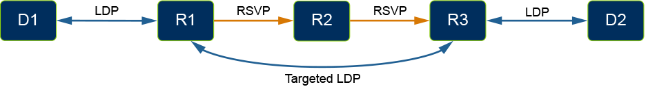
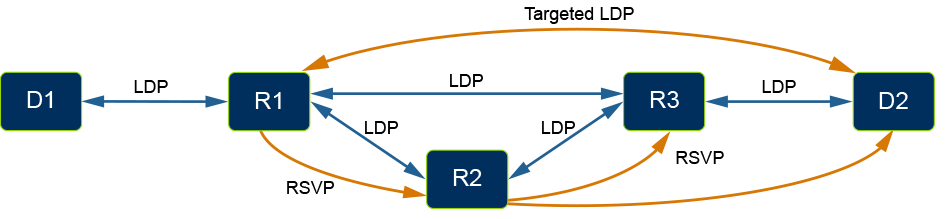
The diagram below shows a case where the downstream LSR for the D2 prefix does not exist at R1 because not all routers in the network are LDP speakers. Specifically R2 would be the IGP next hop for D2 from R1, but R2 does not run LDP. In this situation, a targeted LDP adjacency is used to establish an LDP session between R1 and R3. With LDP tunneling enabled on the RSVP tunnel from R1 to R3 via R2, R1 is able to use R3 as the downstream LSR for the D2 prefix. A single end-to-end LDP LSP is now established from D1 to D2.
Forcing Traffic Off the IGP Path
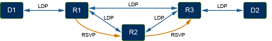
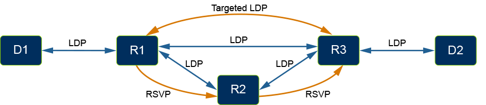
LDP over RSVP can also be used to force LDP traffic over a preferred path other than that given by the IGP. The following diagram shows such a scenario where the IGP next hop for the D2 prefix from R1 is R3. All routers are LDP speakers so R3 could be used as the downstream LSR for the D2 prefix at R1, but the path via R2 is preferred. Enabling LDP tunneling on R1 to R3 via R2 will force the LDP traffic over the RSVP tunnel. When available, RSVP tunnels are always selected by the implementation over IGP next hops. In either case, R3 is the downstream LSR from R1. The choice is on the path taken.
Multi-path Routing
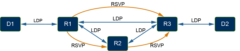
LDP over RSVP will leverage multiple configured RSVP tunnels when the tunnels have the same endpoint. LDP traffic will use ECMP across the selected tunnels. In the following diagram, traffic from R1 to D2 may use either the direct RSVP tunnel from R1 to R3 or the RSVP tunnel from R1 to R3 via R2.
RSVP Tunnel Selection
LDP over RSVP selects RSVP tunnels such that the loop-free condition is guaranteed and the tunnel with the closest endpoint to the destination is always used. To expand on the previous examples, if an RSVP tunnel existed from R1 to D2 via R2 (skipping R3) then it would be used instead of the tunnel from R1 to R3 via R2. ECMP would not be used between the two tunnels because they do not have the same endpoint.
There is a potential problem with RSVP tunnels to non-adjacent routers. With the new RSVP tunnel to D2, R1 will not have a downstream LSR for the D2 prefix unless it has an LDP session with D2. Therefore, a targeted LDP adjacency is required between R1 and D2. This is similar to the situation where an LSR does not have a downstream router for a prefix because it does not have an LDP session with the IGP next hop.
Protecting Against Link Failure
RSVP protection mechanisms can be used to protect the LDP over RSVP data path against link or node failures. However a link failure may also cause an LDP session to go down which would then disrupt the LDP data path. To protect the LDP control plane it is recommended that an LDP Hello Redundancy configuration is used with LDP over RSVP when the routers are adjacent. Hello Redundancy automatically establishes a targeted adjacency with LDP peers for which a link adjacency exists. Targeted adjacencies can be automatically established with RSVP tunnel endpoint LSRs, for tunnels that have LDP tunneling enabled. There is no need to configure Hello Redundancy. Refer to the section Automatic targeted adjacencies for details.
In the following diagram, a targeted adjacency is established between R1 and R3. If the link between R1 and R3 were to fail the LDP session would continue to be supported by the targeted adjacency and LDP data traffic would continue to use the RSVP tunnel from R1 to R3 via R2. If the redundant targeted adjacency did not exist in this scenario, R1 would lose the LDP session with R3 and the IGP next hop for the D2 prefix at R1 would change to R2. LDP traffic would stop using the RSVP tunnel, and the LFIB would need to be re-programmed using the new route, disrupting LDP data traffic.
When Hello Redundancy is used to protect against link failure with LDP over RSVP it is suggested to configure an infinite duration because data traffic may continue in this state indefinitely. This is unlike normal LDP where a non-adjacent LSR cannot be used as a downstream router. In that case Hello Redundancy is only preserving the control plane in case the failed link recovers.
Automatic Targeted Adjacencies
The RSVP tunnel configuration is leveraged to establish LDP targeted adjacencies automatically between LSRs are the endpoints of an RSVP tunnel with LDP tunneling enabled. This feature requires that the RSVP tunnel source and destination addresses are configured to be the same as the LDP transport addresses for the LSRs. If that is not the case, then targeted adjacencies should be configured either through a static configuration or by using Hello Redundancy.
UCMP
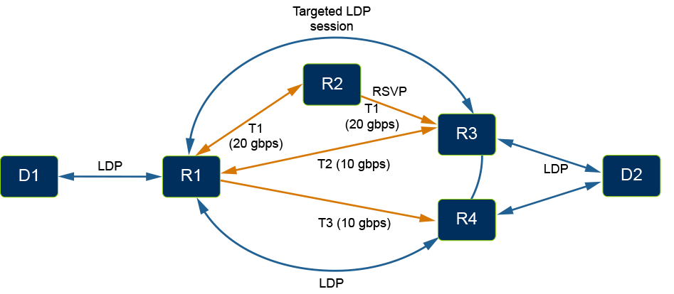
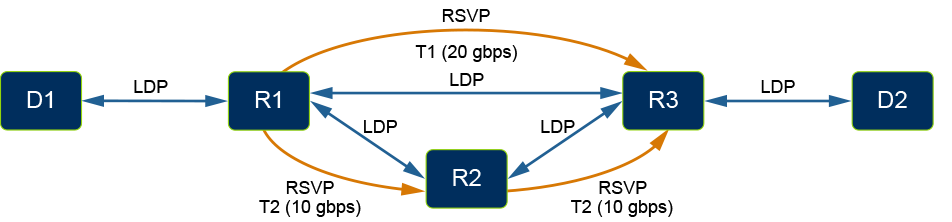
Load balance traffic to prefixes in the ratio of bandwidths can be configured on RSVP tunnels. In the following diagram, T1 is a direct 20 Gbps tunnel from R1 to R3. T2 is another 10 Gbps RSVP tunnel to R3 with a hop at R2. With UCMP for LDP tunneling configuration, traffic from R1 to D2 would be load balanced in the ratio of the bandwidths on the two RSVP tunnels and as a result, tunnel T1 would carry twice as much traffic as tunnel T2.
In the following example, D2 is reachable via RSVP tunnels to multiple tunnel endpoints R3 and R4. With UCMP and bandwidth configuration on all RSVP tunnels, traffic to D2 from R1 will be equally distributed to R3 and R4. Further, traffic destined to R3 is load balanced in the ratio of the specified bandwidths.For example, if the bandwidths on the tunnels are as specified in the figure above and there is 6 Gbps traffic to D2 from R1, tunnels T1, T2 and T3 would carry 2 Gbps, 1 Gbps, and 3 Gbps, respectively.