Multicast Architecture
IP multicast transmits data packets to multiple hosts through a common IP address. Arista switches support multicast transmissions through the Internet Group Management Protocol (IGMP), IGMP Snooping, and PIM Sparse Mode (PIM-SM).
The following topics describe the Arista multicast architecture.
Overview
Arista switches provide Layer 2 multicast filtering and Layer 3 routing features for applications requiring IP multicast services. The switches support over a thousand separate routed multicast sessions at wire speed without compromising other Layer 2/3 switching features. Arista switches support IGMP, IGMP snooping, PIM-SM, and Multicast Source Discovery Protocol (MSDP) to simplify and scale data center multicast deployments.
Supported Features
Feature support varies by platform; consult the release notes for multicast support information by platform.
Multicast and unicast use the same routing table. Unicast routes use TCAM resources, which may impact the maximum number of multicast routes.
Features Not Supported
The multicast functions not supported by Arista switches include (*,*,G) forwarding or boundary routers, multicast MIBs, and router applications joining multicast groups.
Multicast Architecture Description
IP multicast transmits data to a subset of all hosts through a single multicast group address. Similar to unicast packets, multicast packets are delivered using best-effort reliability. Senders use the multicast address as the destination address. Any host, regardless of group membership, can send to a group. However, only group members receive messages sent to a group address.
IP multicast addresses range from 224.0.0.0 to 239.255.255.255. Multicast routing protocol control traffic reserves the address range 224.0.0.0 to 224.0.0.255. The address 224.0.0.0 is never assigned to any group.
Multicast group membership is dynamic; a group's activity level and membership can vary over time. A host can also simultaneously belong to multiple multicast groups.
Multicast Architecture depicts the components that comprise the multicast architecture. The remainder of this section describes the multicast components depicted in the figure.
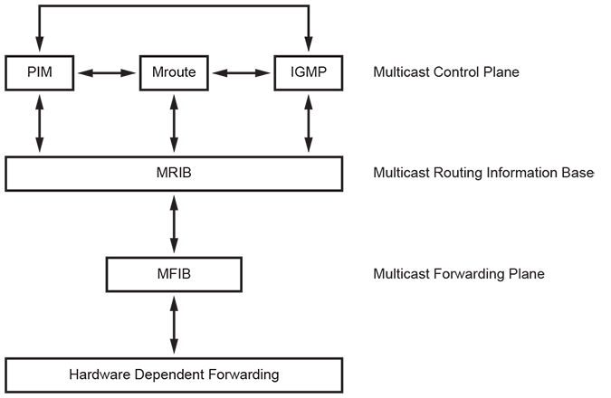
Multicast Control Plane
The multicast control plane builds and maintains multicast distribution trees. It communicates changes in the multicast routing table to the Multicast Forwarding Information Base (MFIB) for multicast forwarding.
- Protocol Independent Multicast (PIM) builds and maintains multicast routing trees using Reverse Path Forwarding (RPF) on a unicast routing table.
- Internet Group Management Protocol (IGMP) identifies multicast group members on subnets directly connected to the switch. Hosts manage multicast group membership with IGMP messages.
- The switch maintains an mroute (multicast routing) table when running PIM to provide forwarding tables used to deliver multicast packets.
The mroute table stores the states of inbound and outbound interfaces for each source/group pair (S,G). The switch discards and forwards packets based on this state information. Each table entry, referred to as an mroute, corresponds to a unique (S,G) and contains:
- the multicast group address
- the multicast source address (or * for all sources)
- the inbound interface
- a list of outbound interfaces
Multicast Routing Information Base (MRIB)
The MRIB is the channel between multicast control plane clients and the multicast forwarding plane. The show ip mroute command displays MRIB entries as (*, G), (S, G), and (*, G/m) multicast entries.
MRIB entries are based on source, group, and group masks. The entries are associated with a list of interfaces whose forwarding state is described with flags. MRIB communication is based on the state change of entry and interface flags. Flags are significant to MRIB clients but are not interpreted by the MRIB.
Multicast Forwarding Plane
The multicast forwarding plane consists of the Multicast Forwarding Information Base (MFIB), a forwarding engine that is independent of multicast routing protocols.
MFIB formats PIM and IGMP multicast routes for protocol-independent hardware packet forwarding and adds them to the hardware Multicast Expansion Table (MET) and the hardware FIB.
MFIB uses a core forwarding engine for interrupt-level (fast switching) and process-level (process switching) forwarding. MFIB fast-switches inbound multicast packets that match an MFIB forwarding entry and process-switches packets requiring a forwarding entry if a matching entry does not exist.
Hardware Dependent Forwarding and Fast Drop
In IP multicast protocols, each (S,G) and (*,G) route corresponds to an inbound Reverse Path Forwarding (RPF) interface. The CPU subsystem software may perform PIM processing on packets that arrive on non-RPF interfaces.
By default, hardware sends all packets arriving on non-RPF interfaces to the CPU subsystem software. However, the CPU can be overwhelmed by non-RPF packets that do not require software processing. The CPU subsystem software prevents CPU overload by creating a fast-drop entry in hardware for inbound non-RPF packets that do not require PIM processing. Packets matching a fast-drop entry are bridged in the ingress VLAN but not sent to the software, avoiding CPU subsystem software overload. Fast-drop entry usage is critical in topologies with persistent RPF failures.
Protocol events, such as links going down or unicast routing table changes, can change the set of packets that can be fast-dropped. Packets that were correctly fast-dropped before a topology change may require forwarding to the CPU subsystem software after the change. The CPU subsystem software handles fast-drop entries that respond to protocol events so that PIM can process all necessary non-RPF packets.
Multicast Listener Discovery (MLD)
Networks use Multicast Listener Discovery (MLD) to control the flow of layer 3 IPv6 multicast traffic. Hosts request and maintain multicast group membership through MLD messages. Multicast routers use MLD to maintain a membership list of active multicast groups for each attached network.
A multicast router is either a querier or non-querier with respect to each of its attached networks. Each physical network contains only one querier. A network with more than one multicast router designates the router with the lowest IP address as its querier.
In an MLD Report or Done message, the multicast address field holds a specific IPv6 multicast address to which the message sender is listening or is ceasing to listen, respectively.
MLDv2 Snooping
MLDv2 Snooping optimizes the transmission of multicast packets in Layer 2 by using Layer 3 information contained in MLDv2 and PIM packets. MLDv2 is the protocol used to manage the membership of hosts in multicast groups for IPv6.
RFC 3810 talks about MLDv2 functionality. MLDv2 is the IPv6 counterpart of IGMPv3. Beginning with eos Release 4.25.0F, MLDv2 snooping is supported on MLAG deployments.
Limitations
- The extraneous “switch” interface should be ignored in show mld snooping counters and show mld snooping counters errors command outputs.
- MLDv2 Snooping with Ethernet VPN (EVPN) is not supported.
- On CCS-720XP, CCS-750, DCS-7050CX3, DCS-7050SX3, DCS-7050TX3, and DCS-7300X3 switches to enable MLDv2 snooping on a VLAN, IGMP snooping needs to be enabled for IPv6 unknown multicast traffic to be forwarded over IPv4 and IPv6 router ports; otherwise, such traffic would flood the entire VLAN. Forwarding IPv6 unknown multicast traffic over only IPv6 router ports is not supported on these platforms.
Configuring Multicast Listener Discovery
Enabling MLD
Use the mld command to enable MLD on an interface. When the switch fills the multicast routing table, it only adds interfaces when the interface receives join messages from downstream devices or when the interface is directly connected to a member of the MLD group. By default, MLD is disabled on an interface.
- This command enables MLD on the interface Ethernet
1.
switch(config)# interface Ethernet 1 switch(config-if-Et1)# mld - This command disables MLD on the interface Ethernet
1.
switch(config)# interface Ethernet1
switch(config-if-Et1)# no mld
Configuring MLD
An interface that runs MLD uses default protocol settings unless otherwise configured. The switch provides commands that alter the startup query, last member query, and normal query settings.
MLD
The mld command configures multicast routers on the configuration mode interface. Version 2 is the default MLD version.
Example
switch(config)# interface Ethernet 1
switch(config-if-Et1)# mld
Startup Query
Membership queries are sent at an increased frequency immediately after an interface starts up to establish the group state quickly. Query count and query interval commands adjust the period between membership queries for a specified number of messages.
The mld startup-query-interval command specifies the interval between membership queries that an interface immediately sends after it starts up. The mld startup-query-count command specifies the number of queries the switch sends from the interface at the startup interval rate.
- This command configures the startup query count of
4 on
interface
Ethernet1.
switch(config)# interface Ethernet1 switch(config-if-Et1)# mld startup-query-count 4 - This command configures the startup query interval of
100 seconds on
interface
Ethernet1.
switch(config)# interface Ethernet1
switch(config-if-Et1)# mld startup-query-interval 100
Membership Queries
The router with the lowest IP address on a subnet sends membership queries as the MLD querier. When a membership query is received from a source with a lower IP address, the router resets its query response timer. Upon timer expiry, the router begins sending membership queries. If the router subsequently receives a membership query originating from a lower IP address, it stops sending membership queries and resets the query response timer.
The mld query-interval command configures the frequency at which the active interface sends membership query messages as an MLD querier.
The mld query-response-interval command configures the time that a host has to respond to a membership query.
- This command configures the query interval of 30
seconds on interface
Ethernet1.
switch(config)# interface Ethernet1 switch(config-if-Et1)# mld query-interval 30 - This command configures the query response interval of
30 seconds on
interface
Ethernet1.
switch(config)# interface Ethernet1
switch(config-if-Et1)# mld query-response-interval 30
Last Member Query
When the querier receives an MLD leave message, it verifies the group has no remaining hosts by sending a series of group-specific queries at a specified interval. If the querier does not receive a response to the queries, it removes the group state and discontinues multicast transmissions.
The mld last-listener-query-count command specifies the number of query messages the router sends in response to a group-specific or group-source-specific leave message.
The mld last-listener-query-interval command configures the transmission interval for sending group-specific or group-source-specific query messages to the active interface.
- This command configures the last listener query count to
3 on
interface
Ethernet1.
switch(config)# interface Ethernet1 switch(config-if-Et1)# mld last-listener-query-count 3 - This command configures the last listener query interval to
2 seconds on
interface
Ethernet1.
switch(config)# interface Ethernet1
switch(config-if-Et1)# mld last-listener-query-interval 2
Static Groups
The mld static-group command configures the configuration mode interface as a static member of the multicast group at the specified address. The router forwards multicast group packets through the interface without otherwise appearing or acting as a group member. No interface is a static member of a multicast group by default.
Example
switch(config)# interface Ethernet1
switch(config-if-Et1)# mld static-group ff30::1 a::1
MLDv2 Snooping Configuration
Enabling or Disabling MLDv2 Snooping
MLDv2 snooping supports global and per-VLAN configuration. The global configuration mode provides access to MLD-related snooping commands.
switch(config)# mld snooping
switch(config-mld-snooping)# disabled
switch(config-mld-snooping)# vlan 1-100
switch(config-mld-snooping)# vlan 101
switch(config-mld-snooping-vlan-101)# disabled- MLDv2 snooping requires an explicit configuration for each VLAN inside the mld-snooping configuration mode to enable snooping for those VLANs.
- Use the global disabled command to disable the mld-snooping for all VLANs. The global disabled setting is off by default.
- Snooping can be explicitly disabled for a given VLAN. This is useful once there is a configuration within the VLAN. The disabled setting is off by default.
- Snooping cannot be explicitly enabled for a given VLAN if it is disabled globally.
- Beginning with the eos Release 4.25.0F, eos allows the configuration of MLD versus snooping on PIM non-DR (Designated Router) VLANs.
Static Groups and Multicast Router
To configure static groups, refer to the following commands:
switch(config)# mld snooping
switch(config-mld-snooping)# vlan 100
switch(config-mld-snooping-vlan-100)# member ipv6-group-addr interface intfs
To configure a static multicast router, refer to the following commands:
switch(config)# mld snooping
switch(config-mld-snooping)# vlan 100
switch(config-mld-snooping-vlan-100)# multicast-router interface intfs
In the examples above, intfs can be a group of similar interfaces (for example, Ethernet1-5,8 or port-channel 1-5,8).
Displaying MLDv2 Snooping Status
-
switch# show mld snooping Global MLD Snooping configuration: ------------------------------------------- MLD snooping : Enabled Robustness variable : 2 VLAN 1 : ---------- MLD snooping : Disabled MLD max group limit : No limit set Recent attempt to exceed limit : No MLD snooping pruning active : False Flooding traffic to VLAN : True VLAN 100 : ---------- MLD snooping : Enabled MLD max group limit : No limit set Recent attempt to exceed limit : No MLD snooping pruning active : True Flooding traffic to VLAN : False -
switch# show mld snooping Global MLD Snooping configuration: ------------------------------------------- MLD snooping : Enabled Robustness variable : 2 VLAN 1 : ---------- MLD snooping : Disabled MLD max group limit : No limit set Recent attempt to exceed limit : No MLD snooping pruning active : False Flooding traffic to VLAN : True VLAN 100 : ---------- MLD snooping : Enabled MLD max group limit : No limit set Recent attempt to exceed limit : No MLD snooping pruning active : True Flooding traffic to VLAN : False -
Use the show mld snooping groups command to display MLDv2 snooping by group.
switch# show mld snooping groups IGMP Snooping Group Membership EX : Filter mode Exclude IN : Filter mode Include IR : Ingress Replication VLAN Group Members ---- --------------- ------------------------ 100 ff05::2 Cpu, Et4 100 ff08::11 Et1 100 ff08::21 Et2 100 ff08::31 Et3 100 * Et3, Et4 -
Use the show mld snooping groups detail command to display detailed MLDv2 snooping information.
switch(config-mld-snooping-vlan-100)# show mld snooping groups detail
IGMP Snooping Group Membership
EX : Filter mode Exclude
IN : Filter mode Include
IR : Ingress Replication
VLAN  Group            Source     Mode  Uptime       Members
----  ---------------  ---------  ----  -----------  ----------
100   ff05::2          *           -     0d00h13m20   Cpu, Et4
100   ff08::11         *           -     0d00h13m17   Et1
100   ff08::21         1::1        IN    0d00h13m20   Et2
100   ff08::31         2::1        EX    0d00h01m31   Et3
100   *                *            -     -           Et3, Et4
Refine the show mld snooping groups output using the following filters:-
local groups - groups learned locally using the show mld snooping groups local command.
-
user groups - groups configured by the user.
- mlag groups - groups learned from the MLAG peer.
-
-
switch# show mld snooping mrouter Vlan Interface-ports ------------------------------------------- 100 Et3(dynamic), Et4(static) -
switch# show mld snooping mrouter detail Vlan Intf Address FirstHeard LastHeard Expires Type --------------------------------------------------------------------------------- 100 Et3 fe80::200:3ff:fe01:0 0d00h24m30 0d00h00m08 00h00m17 querier 100 Et4 fe80::200:3ff:fe03:0 0d00h24m10 0d00h00m08 00h01m37 pim 100 Et2 0.0.0.0 - - - static -
switch# show mld snooping mrouter vlan 100 Vlan Interface-ports ------------------------------------------------------------ 100 Et2(static), Et3(dynamic), Et4(dynamic) -
switch# show mld snooping querier Vlan IP Address Version Port -------------------------------------------- 100 fe80::200:3ff:fe01:0 v2 Et3 -
switch# show mld snooping querier vlan 100 IP Address : fe80::200:3ff:fe01:0 MLD Version : v2 Port : Et3 Max response time : 10.0 -
switch# show mld snooping counters Input | Output Port Queries Reports Others Errors|Queries Reports Others -------------------------------------------------------------- Cpu 1 153 0 0 154 6 51 Et1 0 153 0 0 156 0 51 Et2 0 153 0 0 156 110 51 Et3 154 1 0 0 1 610 51 Et4 0 152 51 0 155 453 0 switch 0 0 0 0 0 0 0 -
switch# show mld snooping counters errors
           Packet       Packet  Bad IP    Unknown      Bad PIM   Bad ICMP  Bad MLD   Bad MLD
Port       Too Short    Not IP  Checksum  IP Protocol  Checksum  Checksum  Query     Report
---------------------------------------------------------------------------------------------
Cpu                0         0         0            0         0         0         0         0
Et1                0         0         0            0         0         0         0         0
Et2                0         0         0            0         0         0         0         0
Et3                0         0         0            0         0         0         0         0
Et4                0         0         0            0         0         0         0         0
switch             0         0         0            0         0         0         0         0
Multicast Route Counters
Multicast Route Counters provides per multicast route ingress packet and byte counters for multicast routed packets.
Configuration
switch(config)# hardware counter feature multicast ipv4switch(config)# no hardware counter feature multicast ipv4switch(config)# hardware tcam
switch(config-hw-tcam)# profile <profileName> copy default
switch(config-hw-tcam-profileName)# feature counter multicast ipv4
switch(config-hw-tcam-profileName-feature-counter-multicast-ipv4))# exit
switch(config-hw-tcam-profileName)# no feature mirror ip
switch(config-hw-tcam-profileName)# exit
switch(config-hw-tcam)# system profile <profileName>Show Commands
Use the show ip mfib counters command to display per multicast route ingress packet and byte counters:
switch# show ip mfib 225.1.2.1 10.46.1.2 counters
Activity poll time: 60 seconds
225.1.2.1 10.46.1.2
Byte: 1200200
Packet: 12002
Ethernet46 (iif)
Ethernet47
Activity 0:02:52 ago
switch#switch# show ip mfib counters
Activity poll time: 60 seconds
225.1.1.1 0.0.0.0/0
Byte: 234100
Packet: 2341
1 (rpaIndex)
Ethernet21
Ethernet23
Activity 1:00:52 ago
225.1.2.1 10.46.1.2
Byte: 1200200
Packet: 12002
Ethernet46 (iif)
Ethernet47
Activity 0:02:52 ago
224.0.0.0/4 10.45.1.0/24
Byte: N/A
Packet: N/A
Ethernet45 (iif)
Cpu
Activity 0:02:04 ago
switch#Use the clear counters command to clear all counters, including per multicast route ingress counters.
switch# clear countersTo clear per multicast route ingress counters or clear counters for a particular multicast route, use the clear ip multicast counters command.
switch# clear ip multicast <vrf [vrf-name]> counters <group_addr> <source_addr>Limitations
- Counters are not supported on fastdrop multicast routes.
- For PIM sparse mode, counters are supported only on (Source_addr, Group_addr) multicast routes.
- Counting is supported for IPv4 multicast packets only.
Multicast (S,G) Counters
The Multicast Route Counters count the packets and bytes per group, source, and Virtual Route Forwarding (VFR). Every multicast route is counted when the Multicast (S,G) counters are enabled and if sufficient hardware counter resources are available. Since the number of hardware counter resources is limited, selected multicast routes can be prioritized to provide them with the needed hardware counter resources over the non-priority multicast routes in case of resource contention.
Priority multicast routes can be configured if:
- Hardware counter resources are available:
- The priority multicast routes do not affect the existing non-priority multicast route counters.
- In case there are insufficient hardware counter
resources:
- If there are non-priority multicast routes, one non-priority multicast route counter resource will be freed, which results in losing the counters for the non-priority multicast route, and the priority multicast route will be programmed, meanwhile the non-priority multicast route will be pending to be programmed until there are hardware counter resources available.
- If there are only priority multicast groups, the newly configured priority multicast groups will wait until existing priority groups free the resources.
Configuring Multicast (S,G) Counters
Configure the multicast (S, G) counters feature using the following command in the configuration mode:
hardware counter feature multicast [ipv4 | ipv6]The hardware counter feature multicast command enables counting all groups as non-priority groups unless the groups requiring priority treatment have been configured under router multicast, as described in the next paragraph. Use the no form of the command to disable the multicast (S, G) counters on a switch.
switch(config)# router multicast
switch(config-router-multicast)# ipv6
switch(config-router-multicast-ipv6)# counters
switch(config-router-multicast-ipv6)# counters ff08::e101:101 2002::a01:101switch(config-router-multicast-ipv6)
command mode before configuring the specific multicast
routes:
switch(config-router-multicast-ipv6)#! 'counters' not configured, packet will not be countedTo clear the counters use the following command:
clear ipv6 multicast [vrf [vrf-name]] counters group sourceThe clear ipv6 multicast command can clear the counters for all multicast routes or a specific vrf, group, or source. The default VRF is used unless an alternate is specified. All IPv6 counters are cleared if no group and source are specified.
The IPv4 version of the command is:
clear ip multicast [vrf [vrf-name]] counters group sourceswitch# clear countersMulticast (S,G) Counters Show Commands
switch# show platform trident flexcounters summary
Feature ID Type Request ID Pool ID Start Index Counters
------------------------------------------------------------------------
Mcast ingress 0 0 1 8191 switch# show platform trident flexcounters multicast summary
Group Source VRF VLAN Counter Index Pool ID Offset Mode Base Counter Index
--------------- -------------- ---- ----- -------------- -------- ----------- ------------------
ff08::e101:101 2002::a01:105 0 2570 1 0 0 1
225.1.1.1 10.1.1.5 0 2571 2 0 0 2switch# show platform trident flexcounters multicast values
Group Source VRF VLAN Counter Index Offset Bytes (cntTbl) Bytes (snapTbl) Pkts (cntTbl) Pkts (snapTbl)
-------------- ------------- --- ---- -------------- --------------------- --------------- ------------- --------------
ff08::e101:101 2002::a01:105 0 2570 1 6600 0 100 0
225.1.1.1 10.1.1.5 0 2571 2 8800 0 100 0switch# show multicast fib ipv6 <vrf [vrf-name]> <group> <source> counters
Activity poll time: 60 seconds
ff08::e101:101 2002::a01:101
Byte: 66
Packet: 1
Vlan2780 (iif)
Ethernet6/4
Vlan2899
switch# show multicast fib ipv4 <vrf [vrf-name]> <group> <source> counters
Activity poll time: 60 seconds
255.1.1.1 10.1.1.5
Byte: 66
Packet: 1
Vlan2781 (iif)
Ethernet8/4
Vlan2999Limitations
The number of counters for which the hardware counters can be enabled simultaneously will be limited by the system's availability of counter hardware resources.
When the configured hardware features exceed the available counter resources, not all counters for all features will be available.
The following CLI command shows the current allocation of the hardware resources:
switch# show platform trident flexcounters summary
Feature ID Type Request ID Pool ID Start Index Counters
---------------------------------------------------------------------
Mcast ingress 0 0 1 8191 Static IP Mroute
The Static IP Multicast route (or Static Mroute) interface overrides the interface that is ordinarily selected from the matching route in the unicast routing table, providing a means for breaking dependency on the unicast topology for the multicast topology. Let us assume that PIM routers in a multicast network send PIM joins toward a source to receive traffic from that source. The interface on which to send a PIM join is determined by looking up the unicast routing table for the source address. This interface is the upstream or RPF interface for that source. When receiving traffic from that source, the system ensures its reception on the RPF interface for that source. This mechanism causes multicast traffic to take the same path through a network as unicast traffic. In some cases, having the multicast traffic take a different path than the unicast traffic is desirable. For example, to avoid a slow firewall required for unicast traffic but not for multicast traffic or to receive multicast across a low latency, low bandwidth microwave link while unicast traverses a higher latency, higher bandwidth fiber path.
eos provides a static IP multicast route (or Static Mroute) ip mroute command to address this situation. The ip mroute command specifies a candidate for the RPF interface of any (S,G) multicast route where the source falls within the given source/mask. This interface potentially overrides the interface that would ordinarily have been selected from the matching route in the unicast routing table. This command, therefore, provides a means of breaking the dependence of the multicast topology on the unicast topology. The method of selecting the RPF interface for an (S,G) route is described later in this document.
Example
switch(config)# ip mroute 1.1.1.1/32 ethernet 2/1 20Selecting Static Mroute
- Longest Match
- Administrative Distance
- Interface Status
Longest Match
The longest match will be selected when a given source matches multiple static Mroutes in the MRIB. The order in which the static Mroutes were configured will not be a factor.
Example
ip mroute 0.0.0.0/0 Ethernet1
ip mroute 192.168.0.0/16 Ethernet2
ip mroute 192.168.1.0/24 Ethernet3| Source | RPF Interface |
| 192.168.1.1 | Ethernet 3 |
| 192.168.1.2 | Ethernet 3 |
| 192.168.2.1 | Ethernet 2 |
| 10.0.0.1 | Ethernet 1 |
Administrative Distance
You can specify an administrative distance with each static Mroute. While selecting a Static Mroute for a source, the one with the lowest Admin distance is selected if multiple Static Mroute exist in the MRIB with the same source/mask. The default administrative distance for a Static Mroute is 1.
Interface Status
For a Static Mroute to be considered for selection, the specified interface must be up and PIM enabled on the interface.
Selecting RPF Interface
Static Mroutes are BGP IP Multicast (SAFI 2) learned routes. A separate routing table, the Multicast Routing Information Base (MRIB), stores these routes. The RPF interface is selected for a source as follows:
initially, the system looks up a source route in the MRIB. If the MRIB lookup yields a route, it uses that route to select the RPF interface. Therefore, any configured Static Mroutes matching the source wins the selection process over a "connected" route to the source. For a static mroute to be considered for selection, the specified interface must be up and PIM enabled on the interface. By default, Static Mroute has an Admin distance of 1. If multiple Static Mroutes exist with equal longest prefix match, the mroute with the lowest Admin distance will win. The Admin distance is not to be used to compare selection between unicast RIB and MRIB routes. A successful Static Mroute lookup in the MRIB is always chosen over unicast RIB lookups.
If the MRIB lookup does not yield a route, the unicast RIB is looked up for a route to select the RPF interface. If the selected route has ECMP, one of the corresponding paths is selected as the RPF neighbor.
Example
ip mroute 172.16.0.0/16 Ethernet1
ip mroute 192.168.0.0/16 Ethernet2
ip mroute 192.168.1.0/24 Ethernet3
ip mroute 192.168.1.0/24 Ethernet4 255
ip mroute 192.168.1.3/32 Ethernet5 255
ip mroute 200.10.0.0/16 Ethernet5
ip mroute 200.11.0.32/16 Ethernet5| Prefix | Interface | Admin Distance |
| 172.16.0.0/16 | Ethernet 1 | 1 |
| 192.168.0.0/16 | Ethernet 2 | 1 |
| 192.168.1.0/24 | Ethernet 3 | 1 |
| 192.168.1.0/24 | Ethernet 4 | 255 |
| 192.168.1.3/32 | Ethernet 5 | 255 |
| 200.10.0.0/16 | Ethernet 5 | 1 |
| 200.11.0.1/32 | Ethernet 5 | 1 |
| Prefix | Interface | Protocol | Admin Distance |
| 10.0.0.0/24 | Ethernet 6 | OSPF | 110 |
| 172.16.1.0/24 | Ethernet 7 | OSPF | 110 |
| 192.168.0.0/16 | Ethernet 8 | OSPF | 110 |
| 192.168.1.0/24 | Ethernet 9 | Static | 1 |
| 192.168.1.3/32 | Ethernet 10 | OSPF | 110 |
| 200.10.0.0/16 | Ethernet 11 | Connected | 0 |
| Source | Static Mroute | Unicast Route | Winner | RPF Interface | Reasoning |
| 10.0.0.1 | - | 1 | Unicast Route | Ethernet 6 |
Only the unicast Rib yields a route to the source so it wins. |
| 200.11.0.1 | 7 | - | Static Mroute | Ethernet 5 |
Only the MRIB yields a route to the source so it wins. |
| 192.168.1.3 | 5 | 5 | Unicast Route | Ethernet 10 |
In the MRIB (5) is the longest match. While comparing the static mroute and the unicast route, the unicast route is the winner because it has a lower Admin distance. |
| 192.168.2.1 | 2 | 3 | Static Mroute | Ethernet 2 |
In the MRIB (2) is the longest match. While comparing the static mroute and the unicast route, the static Mroute is the winner because it has a lower Admin distance. |
| 192.168.1.1 | 3 | 4 | Static Mroute | Ethernet 3 |
In the MRIB both (3) and (4) are the longest match but (3) has the lower Admin distance While comparing the static mroute and the unicast route, the static mroute is the winner even though both have the same distance. |
Static Multicast
Static Multicast configures multicast routes statically on Arista switches and per VRF granularity. However, static multicast routes do not perform any VRF validation for the interfaces involved in the route, which can lead to route leakage. Static Multicast coexists with PIM-SM and PIM-BIDIR protocols, which are dynamic variants of programming multicast routes. However, to obtain the best results, choose the appropriate route selection method before the static routes are programmed.
Static multicast routes compete with the routes provided by PIM-SM and PIM-BIDIR mainly because this static variant allows the configuration of PIM-SM-like or PIM-BIDIR-like routes, among other routes. The route chosen depends upon the priority setting.
Currently, PIM-SM/PIM-BIDIR installs routes with a priority value of 0 (zero), while static routes install routes with a priority of 255 by default.
The priorities of PIM-SM and PIM-BIDIR are subject to future change. A higher priority wins in the case of conflicts while programming the hardware. Any conflicts here imply the same route is present as a static multicast route and in a PIM-SM or PIM-BIDIR. It concludes that, by default, static multicast routes will always be the winner.
Configuring Multicast
This section describes the following configuration tasks:
Enabling IPv4 Multicast Routing
Enabling IPv4 multicast routing allows the switch to forward multicast packets. The routing command enables multicast routing. When multicast routing is enabled, running-config contains a routing statement.
Example
switch(config)# router multicast
switch(config-router-multicast)# ipv4
switch(config-router-multicast-ipv4)# routingEnabling IPv6 Multicast Routing
Enabling IPv6 Multicast routing allows the switch to distribute IPv6 datagrams to one or more recipients. IPv6 PIM builds and maintains Multicast routing using Reverse Path Forwarding (RPF) based on a unicast routing table. IPv6 PIM is protocol-independent and can use routing tables consisting of OSPFv3, IPv6 BGP, or static routes for RPF lookup. MLD is used to discover Multicast hosts and maintain group membership on a directly attached link. This feature is supported on 7280R and 7500R. Source-specific multicast (SSM) is currently supported on the L3 routed port.
PIM Sparse Mode
In PIM-SM, each host (sender or receiver) is associated with a Designated Router (DR), which acts for all directly connected hosts in PIM-SM transactions. Upon receiving an MLD report from a host or a PIM join from a downstream PIM neighbor, a (S,G) route is created or programmed, and the router sends a PIM join to the upstream PIM neighbor with the shortest path to the source.
Configuring IPv6 Multicast Routing
The following steps are to configure IPv6 multicast routing on the switch.
- Enabling IPv6 multicast routing.
By default, eos disables multicast routing on the switch. Use the following commands to enable IPv6 multicast routing and software forwarding using the Software Forwarding Engine.
Example
switch(config)# router multicast switch(config-router-multicast)# ipv6 switch(config-router-multicast-ipv6)# routing switch(config-router-multicast-ipv6)# software-forwarding sfe - Enabling IPv6 PIM Sparse Mode.
By default, eos disables IPv6 PIM on an interface. The pim ipv6 sparse-mode command enables an interface to participate in the IPv6 multicast-routing domain.
Example
switch(config)# interface ethernet 15/1 switch(config-if-Et15/1)# pim ipv6 sparse-modeNote: eos does not support SVI. - Configure the checksum header and the local interface loopback to use for PIM
IPv6 register messages:
switch(config)# router pim sparse-mode switch(config-router-pim-sparse)# ipv6 switch(config-router-pim-sparse-ipv6)# register checksum header switch(config-router-pim-sparse-ipv6)# register local-interface loopback 2 - Enabling MLD.
By default, eos disables MLD on an interface. Enable MLD only on the interface connected to the MLD host that receives IPv6 multicast traffic.
Exampleswitch(config)# interface ethernet 15/1 switch(config-if-Et15/1)# mld
Multicast-Routing Configuration Example
Use the following commands to display MLD and IPv6 configuration details:
switch# show running-configuration section router
router multicast
ipv6
routing
software-forwarding sfe
switch# show running-config interfaces ethernet 15/1
interface Ethernet15/1
no switchport
ipv6 enable
ipv6 address 40:1::3/64
mld
pim ipv6 sparse-modeDisplaying IPv6 Multicast Routing Information
switch# show mld membership
Interface Group Source
Filter Mode
--------------------------------------------------
Ethernet2/1.1 ff33::1:0:0:1 101:1::2
include
Ethernet2/1.1 ff33::1:0:0:2 101:1::2
include
Ethernet2/1.1 ff33::1:0:0:3 101:1::2
include
Ethernet2/1.1 ff33::1:0:0:4 101:1::2
include
Ethernet2/1.1 ff33::1:0:0:5 101:1::2
include
Ethernet2/1.1 ff33::1:0:0:6 101:1::2
include
Ethernet2/1.1 ff33::1:0:0:7 101:1::2
include
Ethernet2/1.1 ff33::1:0:0:8 101:1::2
include
Ethernet2/1.1 ff33::1:0:0:9 101:1::2
include
Ethernet2/1.1 ff33::1:0:0:a 101:1::2
include
Ethernet2/1.1 ff33::1:0:0:b 101:1::2
includeswitch# show pim ipv6 sparse-mode route
PIM Sparse Mode Multicast Routing Table
Flags: E - Entry forwarding on the RPT, J - Joining to the SPT
R - RPT bit is set, S - SPT bit is set, L - Source is attached
W - Wildcard entry, X - External component interest
I - SG Include Join alert rcvd, P - (*,G) Programmed in hardware
H - Joining SPT due to policy, D - Joining SPT due to protocol
Z - Entry marked for deletion, C - Learned from a DR via a register
A - Learned via Anycast RP Router, M - Learned via MSDP
N - May notify MSDP, K - Keepalive timer not running
T - switching Incoming Interface, B - Learned via Border Router
RPF route: U - From unicast routing table
M - From multicast routing table
ff33::1:0:0:1
101:1::2, 2:03:00, flags: S
Incoming interface: Ethernet11/1
RPF route: [U] 101:1::/64 [110/1] via fe80::464c:a8ff:feb7:39e9
Outgoing interface list:
Ethernet6/1.1
Ethernet4/1.1
Ethernet7/1.1
Ethernet9/1.1
Ethernet8/1.1
Ethernet2/1.1
Ethernet5/1.1
Ethernet3/1.1
switch# show mfib ipv6
Activity poll time: 60 seconds
ff33::1:0:0:1 101:1::2
Ethernet11/1 (iif)
Ethernet9/1.1
Ethernet2/1.1
Ethernet3/1.1
Ethernet6/1.1
Ethernet5/1.1
Ethernet8/1.1
Ethernet7/1.1
Ethernet4/1.1
Activity 0:00:35 agoswitch# show platform fap mroute ipv6
Jericho0 Multicast Routes:
--------------------------
Location GroupId Group Source
IIF McId OIF
FLP/TT FLP/TT TT FLP
FLP FLP FLP
--------------------------------------------------------------------
4096/2048 1/1 ff33::1:0:0:23/128 101:1::2/128
Vlan1357 21504 Vlan1044(Et7/1) Vlan1123(Et9/1)
Vlan1200(Et8/1) Vlan1223(Et2/1)
Vlan1226(Et5/1) Vlan1232(Et3/1)
Vlan1307(Et6/1) Vlan1337(Et4/1)Configuring a Multicast Boundary
The multicast boundary specifies subnets that filter source traffic entering an interface to prevent the creation of mroute states on the interface. The interface The Outgoing Interface List (OIL) does not include the interface. Multicast PIM, IGMP, and other multicast data cannot cross the boundary, facilitating the use of a multicast group address in multiple administrative domains.
In addition, an interface with a boundary ACL filters any joins (RX or TX) for groups denied by the ACL. This also applies to multicast boundary ACLs with the s option.
The ip multicast boundary command configures the multicast boundary. The multicast boundary can be specified through multiple IPv4 subnets or one standard IPv4 ACL.
In an ACL method, the permit entries of the ACL allow the multicast subnets and denies or filters the rest. In contrast, in a non-ACL method, the statements configure only denied or filtered subnets.
- These commands configure the multicast address of
229.43.23.0/24 as a
multicast boundary restricting source traffic from
interface vlan
300.
switch(config)# interface vlan 300 switch(config-if-vl300)# ip multicast boundary 229.43.23.0/24 switch(config-if-vl300)# - These commands create a standard ACL, then implement the ACL in an
ip multicast boundary
command to deny multicast traffic to 225.130.0.0/16 and 239.120.10.0/24
subnets and allow multicast traffic to all remaining subnets.
switch(config)# ip access-list standard mbac1 switch(config-std-acl-mbac1)# 10 deny 225.123.0.0/16 switch(config-std-acl-mbac1)# 20 deny 239.120.10.0/24 switch(config-std-acl-mbac1)# 30 permit 224.0.0.0/4 switch(config-std-acl-mbac1)# exit switch(config)# interface vlan 200 switch(config-if-Vl200)# ip multicast boundary mbac1 switch(config-if-Vl200)# exit switch(config)#
Multicast multipath router-ID (IPv4)
The multipath deterministic command with the router-id allows downstream PIM neighbors to direct traffic for a group or source-group route through only the specified upstream PIM neighbor for all downstream PIM neighbors with the same ECMP routes. Traffic is load balanced by group or source-group across upstream PIM neighbors as in the default multipath mode.
Multipath router-ID uses the Interface Identifier (from the Hello Option for PIM) to give PIM-enabled devices a globally unique router ID for each of their PIM neighbors.
The following configures the switch to use the router ID.
switch(config)# router multicast
switch(config-router-multicast)# ipv4
switch(config-router-multicast-ipv4)# multipath deterministic router-idThe following displays the switch before the configuration.
switch(config-router-multicast-ipv4)# show active all
router multicast
ipv4
counters bytes
activity polling-interval 60
no routing
multipath deterministic
max-fastdrops 1024
unresolved cache-entries max 4000
unresolved packet-buffers max 3
software-forwarding kernelThe following displays the switch after the configuration.
switch(config-router-multicast-ipv4)# show active all
router multicast
ipv4
counters bytes
activity polling-interval 60
no routing
multipath deterministic router-id
max-fastdrops 1024
unresolved cache-entries max 4000
unresolved packet-buffers max 3
software-forwarding kernelConfiguring MFIB
Multicast Forwarding Information Base (MFIB) formats PIM and IGMP multicast routes for protocol-independent hardware packet forwarding and adds them to the hardware Multicast Expansion Table (MET) and the hardware Forwarding Information Base (FIB).
MFIB Polling Interval
After polling the corresponding hardware activity bits, the switch records activity levels for multicast routes in the MFIB. The activity polling-interval command specifies the frequency at which the switch polls the hardware activity bits for the multicast routes.
Example
switch(config)# router multicast
switch(config-router-multicast)# ipv4
switch(config-router-multicast-ipv4)# activity polling-interval 15
switch(config-router-multicast-ipv4)#MFIB Fast Drops
In IP multicast protocols, every (S,G) or (*,G) route is associated with an inbound Reverse Path Forwarding (RPF) interface. Packets arriving on an interface not associated with the route may need CPU-dependent PIM processing, so packets received by non-RPF interfaces are sent to the CPU by default, causing heavy CPU processing loads.
Multicast routing protocols often do not require non-RPF packets; these packets do not require software processing. The CPU, therefore, updates the hardware MFIB with a fast-drop entry when it receives a non-RPF interface packet that PIM does not require. Additional packets that match the fast-drop entry are not sent to the system software.
Fast drop is enabled on all interfaces by default. The no ip mfib fastdrop command disables MFIB fast drop for the configuration mode interface.
Example
switch(config)# interface vlan 120
switch(config-if-Vl120)# no ip mfib fastdrop
switch(config-if-Vl120)#The ip mfib max-fastdrops command limits the number of fast-drop routes the switch's MFIB table can contain. The default fast-drop route limit is 1024.
Example
switch(config)# ip mfib max-fastdrops 2000
switch(config)#The clear ip mfib fastdrop command, in global configuration mode, removes all MFIB fast-drop entries on all interfaces.
Example
switch# clear ip mfib fastdrop
switch#- show multicast fib ipv4 displays MFIB information for hardware-forwarded routes.
- show multicast fib ipv4 software displays MFIB information for software-forwarded routes.
Example
switch# show multicast fib ipv4
Activity poll time: 60 seconds
239.255.255.250 172.17.26.25
Vlan26 (iif)
Vlan2028
Cpu
Activity 0:02:11 ago
239.255.255.250 172.17.26.156
Vlan26 (iif)
Vlan2028
Cpu
Activity 0:02:11 ago
239.255.255.250 172.17.26.178
Vlan26 (iif)
Vlan2028
Cpu
Activity 0:03:37 ago
switch#MFIB Unresolved Cache-entries Max
The unresolved cache-entries max command configures the maximum number of unresolved (S,G) routes that the switch can cache packets. All packets belonging to (S,G) routes exceeding the limit are dropped. The default buffer size is 4000 routes. See ip multicast boundary to limit the number of cached packets per S,G.
Example
switch(config)# router multicast
switch(config-router-multicast)# ipv4
switch(config-router-multicast-ipv4)# unresolved cache-entries max 6000
switch(config-router-multicast-ipv4)#MFIB Unresolved Packet-buffers Max
The ip multicast boundary command specifies the number of queued packets per unresolved route while the switch resolves the route. The limit for ip multicast boundary is for an individual route; packets that exceed this limit are dropped. By default, the switch processes three unresolved packets for an individual route. Refer to and use the unresolved cache-entries max command to limit the number of cached unresolved routes.
Example
switch(config)# router multicast
switch(config-router-multicast)# ipv4
switch(config-router-multicast-ipv4)# unresolved packet-buffers max 30
switch(config-router-multicast-ipv4)#Configuring Static Multicast
Use the route command to configure the Static Multicast in the Router Multicast mode.
switch(config)# router multicast
switch(config-router-multicast)# routeConfiguring Static Multicast routes for a VRF
To maintain backward compatibility for the default VRF, static multicast commands for the default VRF can be entered without changing to router multicast mode.
Example
switch(config)# router multicast
switch(config-router-multicast)# routeEntering a source address is optional. However, when no source address is specified, it is assumed to be 0.0.0.0.
switch(config-router-multicast)# route 1.1.1.1 10.1.1.1
switch(config-router-multicast)# route 1.1.1.1 10.1.1.1 iifswitch(config-router-multicast)# route 1.1.1.1 10.1.1.1 iif ethernet
switch(config-router-multicast)# route 1.1.1.1 10.1.1.1 iif ethernet 30
switch(config-router-multicast)# route 1.1.1.1 10.1.1.1 iif ethernet 30 oifMultiple ethernet interfaces can be entered following the outgoing interface (oif). However, OIF is also optional. When no OIFs exist, traffic for the S,G on the incoming interface is dropped.
switch(config-router-multicast)# route 1.1.1.1 10.1.1.1 iif ethernet 30 oif ethernet
switch(config-router-multicast)# route 1.1.1.1 10.1.1.1 iif ethernet 30 oif ethernet 30 ethernet 32
switch(config-router-multicast)# route 1.1.1.1 10.1.1.1 iif ethernet 30 oif ethernet 30 ethernet 32 cpu priorityIf required, use the CPU option to set the CPU in the OIF. Setting the priority is also optional, ranging from 1 to 255. By default, the value is 255.
switch(config-router-multicast)# route 1.1.1.1 10.1.1.1 iif ethernet 30 oif ethernet 30 ethernet 32 cpu priority 40Displaying Static Multicast Information
Use the show multicast fib ipv4 command to verify the status of the Static Multicast configured interfaces.
switch# show multicast fib ipv4
Activity poll time: 60 seconds
225.1.1.1 10.1.1.1
Ethernet1 (iif)
Ethernet2
CpuDisplaying and Clearing the Mroute Table
- the multicast group address
- the multicast source address (or * for all sources)
- the inbound interface
- a list of outbound interfaces
Clearing mroute Entries
- clear ip mroute * all entries from the mroute table.
- clear ip mroute gp_ipv4 all entries for the specified multicast group.
- clear ip mroute gp_ipv4 src_ipv4 all entries for the specified source sending to a specified group.
Examples
This command removes all route entries from the mroute table.
switch# clear ip mroute *
switch#switch# clear ip mroute 224.2.205.42 228.3.10.1
switch#Displaying the mroute Table
The show ip mroute count command displays IP multicast routing table statistics.
Example
switch# show ip mroute count
IP Multicast Statistics
1 groups and 1 sources
Multicast routes: 1 (*,G), 1 (S,G)
Average of 1.00 sources per group
Maximum of 1 sources per group:
228.24.12.1
switch>- show ip mroute displays information for all routes in the table.
- show ip mroute gp_addr displays information for the specified multicast group.
Example
switch# show ip mroute 225.1.1.1
PIM Sparse Mode Multicast Routing Table
Flags: E - Entry forwarding on the RPT, J - Joining to the SPT
R - RPT bit is set, S - SPT bit is set
W - Wildcard entry, X - External component interest
I - SG Include Join alert rcvd, P - Ex-Prune alert rcvd
H - Joining SPT due to policy, D - Joining SPT due to protocol
Z - Entry marked for deletion
A - Learned via Anycast RP Router
225.1.1.1
172.28.1.100, 5d04h, flags: S
Incoming interface: Vlan281
Outgoing interface list:
Port-Channel999
switch>Multicast Commands
Multicast Configuration Commands (Global)
- activity polling-interval
- hardware counter feature multicast ipv4
- ip mfib max-fastdrops
- ip mroute
- ip multicast static
- mld last-listener-query-count
- mld last-listener-query-interval
- mld query-interval
- mld query-response-interval
- mld robustness
- mld snooping
- mld startup-query-count
- mld startup-query-interval
- mld static-group
- mld
- multipath deterministic
- multipath none
- route
- router multicast
- routing
- rpf route
- unresolved cache-entries max
- unresolved packet-buffers max
Multicast Configuration Commands (Interface)
Multicast Clear Commands
Multicast Display Commands
- show ip mroute
- show ip mfib counters
- show ip mroute count
- show ip multicast boundary
- show mld membership
- show mld querier
- show mld snooping
- show mld statistics
- show mld summary
- show multicast fib ipv4
- show multicast fib ipv4 software
- show multicast fib ipv6
- show pim ipv6 sparse-mode route
- show platform fap mroute ipv6
activity polling-interval
The switch records activity levels for multicast routes in the mfib after polling the corresponding hardware activity bits. The activity polling-interval command specifies the frequency at which the switch polls the hardware activity bits for the multicast routes.
The no activity polling-interval and default activity polling-interval commands restore the default interval of 60 seconds by removing the activity polling-interval command from running-config.
Command Mode
Router Multicast IPv4 Configuration
Command Syntax
activity polling-interval period
no activity polling-interval
default activity polling-interval
Parameter
period interval (seconds) between polls. Values range from 1 to 60. Default is 60.
Example
switch(config)# router multicast
switch(config-router-multicast)# ipv4
switch(config-router-multicast-ipv4)# activity polling-interval 15
switch(config-router-multicast-ipv4)#clear ip mfib fastdrop
The clear ip mfib fastdrop command removes all fast-drop entries from the MFIB table.
Command Mode
Privileged EXEC
Command Syntax
clear ip mfib fastdrop
Example
switch# clear ip mfib fastdrop
switch#clear ip mroute
- clear ip mroute * removes all entries from the mroute table.
- clear ip mroute gp_ipv4 removes all entries for the specified multicast group.
- clear ip mroute gp_ipv4src_ipv4 removes all entries for the specified source sending to the specified group.
Command Mode
Privileged EXEC
Command Syntax
clear ip mroute ENTRY_LIST
Parameters
- * all route entries.
- gp_ipv4 all entries for multicast group gp_ipv4 (dotted decimal notation)
- gp_ipv4 src_ipv4 all entries for source (src_ipv4) sending to group (gp_ipv4)
- This command removes all route entries from the mroute
table.
switch# clear ip mroute * switch# - This command removes entries for the source
228.3.10.1 sending to multicast group
224.2.205.42.
switch# clear ip mroute 224.2.205.42 228.3.10.1 switch#
clear ip multicast counters
To clear per multicast route ingress counters or clear counters for a particular multicast route, use the clear ip multicast counters command.
Command Mode
EXEC
Command Syntax
clear ip multicast [vrf [vrf-name]] counters group_addr source_addr
- vrf vrf-name VRF name.
- counters Counter for bytes/packets.
- group_addr Group address.
- source_addr Source address.
hardware counter feature multicast ipv4
Use the hardware counter feature multicast ipv4 command to enable per multicast router ingress packets and byte counters. The no and default forms of the command disables the feature. The feature is disabled by default.
Command Mode
Configuration mode
Command Syntax
hardware counter feature multicast ipv4
no hardware counter feature multicast ipv4
default hardware counter feature multicast ipv4
Example
switch(config)# hardware tcam
switch(config-hw-tcam)# profile <profileName> copy default
switch(config-hw-tcam-profileName)# feature counter multicast ipv4
switch(config-hw-tcam-profileName-feature-counter-multicast-ipv4))# exit
switch(config-hw-tcam-profileName)# no feature mirror ip
switch(config-hw-tcam-profileName)# exit
switch(config-hw-tcam)# system profile <profileName>ip mfib fastdrop
In IP multicast protocols, every (S,G) or (*,G) route is associated with an inbound Reverse Path Forwarding (RPF) interface. Packets arriving on an interface not associated with the route may need CPU-dependent PIM processing, so packets received by non-RPF interfaces are sent to the CPU by default, causing heavy CPU processing loads.
Multicast routing protocols often do not require non-RPF packets; these packets do not require software processing. The CPU therefore updates the hardware MFIB with a fast-drop entry when it receives a non-RPF interface packet that PIM does not require. Additional packets that match the fast-drop entry are not sent to the system software.
Fast drop is enabled on all interfaces by default. The no ip mfib fastdrop command disables MFIB fast drop for the configuration mode interface.
The ip mfib fastdrop and default ip mfib fastdrop commands enable MFIB fast drop for the configuration mode interface by removing the corresponding no ip mfib fastdrop command from running-config.
The clear ip mfib fastdrop command, in the global configuration mode, removes all MFIB fast-drop entries on all interfaces.
Command Mode
Interface-Ethernet Configuration
Interface-Port-channel Configuration
Interface-VLAN Configuration
Command Syntax
ip mfib fastdrop
no ip mfib fastdrop
default ip mfib fastdrop
Example
switch(config)# interface vlan 120
switch(config-if-Vl120)# no ip mfib fastdrop
switch(config-if-Vl120)#ip mfib max-fastdrops
The ip mfib max-fastdrops command limits the number of fast-drop routes that the switchs MFIB table can contain.
The no ip mfib max-fastdrops and default ip mfib max-fastdrops commands restore the default fast-drop route limit of 1024 by removing the ip mfib max-fastdrops command from running-config.
Command Mode
Global Configuration
Command Syntax
ip mfib max-fastdrops quantity
no ip mfib max-fastdrops
default ip mfib max-fastdrops
Parameters
quantity maximum number of fast-drop routes. Value ranges from 0 to 1000000 (one million). Default is 1024.
Example
switch(config)# ip mfib max-fastdrops 2000
switch(config)#ip mroute
The ip mroute command configures the Static Mroute on the switch.
The no ip mroute and default ip mroute commands remove the specified static mroute from running-config.
Command Mode
Global Configuration
Command Syntax
ip mroute [source-prefix | source-address mask] [rpf-interface | rpf-neighbor] [admin distance]
Example
switch(config)# ip mroute 1.1.1.1/32 ethernet 2/1 20 ip multicast boundary
The ip multicast boundary command specifies subnets where source traffic entering the configuration mode interface is dropped, preventing the creation of mroute states on the interface. The interface is not included in the Outgoing Interface List (OIL). The multicast boundary can be specified through multiple IPv4 subnets or one standard IPv4 ACL.
In an ACL method, the multicast subnets are allowed only from the permit entries of the ACL and rest is either denied or filtered. Whereas, in a non-ACL method the statements configure subnets that are only denied or filtered.
Multicast PIM, IGMP and other multicast data cannot cross the boundary, facilitating the use of a multicast group address in multiple administrative domains.
The no ip multicast boundary and default ip multicast boundary commands delete the specified subnet restriction by removing the corresponding ip multicast boundary command from running-config. When these commands do not specify a subnet address, all ip multicast boundary statements for the configuration mode interface are removed.
Command Mode
Interface-Ethernet Configuration
Interface-Port-channel Configuration
Interface-VLAN Configuration
Command Syntax
ip multicast boundary SUBNET [TCAM]
no ip multicast boundary [SUBNET]
default ip multicast boundary [SUBNET]
- SUBNET the subnet address configured as the
multicast boundary. Options include:
- net_addr multicast subnet address (CIDR or address mask).
- acl_name standard access Control List (ACL) that specifies the multicast group addresses.
- TCAM specifies address inclusion in the routing
table. Options include:
- no parameter boundaries ((S,G) entries) are added to routing table.
- out boundaries are not added to routing table.
Guidelines
When out is selected, the first inbound data packet corresponding to the SUBNET may be sent to the CPU. In response, the packet is dropped and the boundary prefix is added to the hardware table. In this scenario, the mroute entry is added only when data traffic is received.
Restrictions
Only one command that specifies an ACL can be assigned to an interface. Commands that specify an ACL and a subnet cannot be simultaneously assigned to an interface.
- This command configures the multicast address of
229.43.23.0/24 as a multicast boundary
where source traffic is restricted from interface vlan
300.
switch(config)# interface vlan 300 switch(config-if-vl300)# ip multicast boundary 229.43.23.0/24 switch(config-if-vl300)# - These commands create a standard ACL, then implement the ACL in an ip
multicast boundary command to allow multicast for subnet
(224.0.0.0/4) and create a multicast
boundary for all remaining subnets by denying them.
switch(config)# ip access-list standard mbac1 switch(config-std-acl-mbac1)# 10 deny 225.123.0.0/16 switch(config-std-acl-mbac1)# 20 deny 239.120.10.0/24 switch(config-std-acl-mbac1)# 30 permit 224.0.0.0/4 switch(config-std-acl-mbac1)# exit switch(config)# interface vlan 200 switch(config-if-Vl200)# ip multicast boundary mbac1 switch(config-if-Vl200)# exit switch(config)#
ip multicast static
The ip multicast static command enables static multicast routing on the switch.
The exit command returns the switch to global configuration mode.
Command Mode
Interface Ethernet Configuration
Command Syntax
ip multicast static
Example
switch(config)# interface ethernet 1/2
switch(config-if-Et1/2)# no switchport
switch(config-if-Et1/2)# ip address 1.1.1.1/24
switch(config-if-Et1/2)# ip multicast staticmld last-listener-query-count
The mld last-listener-query-count command specifies the number of query messages the switch sends in response to a group-specific or group-source-specific leave message.
After receiving a message from a host leaving a group, the switch sends query messages at intervals specified by mld last-listener-query-interval. If the switch does not receive a response to the queries after sending the number of messages specified by this parameter, it stops forwarding messages to the host.
The no mld last-listener-query-count and default mld last-listener-query-count commands reset the last-listener-query-count to the default value by removing the corresponding mld last-listener-query-count command from the running-config. Default value is 2.
Command Mode
Interface-Ethernet Configuration
Command Syntax
mld last-listener-query-count number
no mld last-listener-query-count
default mld last-listener-query-count
Parameter
number the last listener query count. Values range from 0 to 100. Default value is 2.
Example
switch(config)# interface Ethernet 1
switch(config-if-Et1)# mld last-listener-query-count 3mld last-listener-query-interval
The mld last-listener-query-interval command configures the switchs transmission interval for sending group-specific or group-source-specific query messages from the configuration mode interface.
When a switch receives a message from a host that is leaving a group, it sends query messages at intervals set by this command. The mld last-listener-query-count specifies the number of messages that are sent before the switch stops forwarding packets to the host.
If the switch does not receive a response after this period, it stops forwarding traffic to the host on behalf of the group, source, or channel.
The no mld last-listener-query-interval and default mld last-listener-query-interval commands reset the last-listener-query-interval to the default value by removing the corresponding mld last-listener-query-interval command from the running-config. Default value is 1 second.
Command Mode
Interface-Ethernet Configuration
Command Syntax
mld last-listener-query-interval period
no mld last-listener-query-interval
default mld last-listener-query-interval
Parameter
period the last listener query interval in seconds. Values range from 1 to 3175.
Example
switch(config) #interface Ethernet1
switch(config-if-Et1)# mld last-listener-query-interval 2mld query-interval
The mld query-interval command configures the frequency at which the configuration mode interface, as an MLD querier, sends host-query messages.
An MLD querier sends host-query messages to discover the multicast groups that have members on networks attached to the interface. The switch implements a default query interval of 125 seconds.
The no mld query-interval and default mld query-interval commands reset the query interval to the default value by removing the corresponding mld query-interval command from the running-config.
Command Mode
Interface-Ethernet Configuration
Command Syntax
mld query-interval period
no mld query-interval
default mld query-interval
Parameter
period the interval between query messages in seconds. Values range from 1 to 3175.
Example
switch(config)# interface Ethernet1
switch(config-if-Et1)# mld query-interval 30mld query-response-interval
The mld query-response-interval command configures the maximum response time that the recipient can wait before responding with a membership report on receipt of a general query.
The no mld query-response-interval and default mld query-response-interval commands reset the query interval to the default value by removing the corresponding mld query-response-interval command from the running-config.
Command Mode
Interface-Ethernet Configuration
Command Syntax
mld query-interval period
no mld query-interval
default mld query-interval
Parameter
period the query response interval in seconds. Values range from 1 to 3175.
Example
switch(config)# interface Ethernet1
switch(config-if-Et1)# mld query-response-interval 30mld robustness
The mld robustness command configures the number of general queries to be sent before the router assumes there are no more listeners.
The no mld robustness and default mld robustness commands reset the robustness to the default value by removing the corresponding mld robustness command from the running-config.
Command Mode
Interface-Ethernet Configuration
Command Syntax
mld robustness robust_value
no mld robustness
default mld robustness
Parameter
robust_value the robustness count. Values range from 1 to 100.
Example
switch(config)# interface Ethernet1
switch(config-if-Et1)# mld robustness 2mld snooping
Multicast Listener Discovery (MLD) snooping constrains the flooding of IPv6 multicast traffic on VLANs and IGMP snooping for IPv4 environments. When MLD snooping is enabled on a VLAN, the device examines MLD messages between the hosts and multicast routers and learns which hosts are interested in receiving traffic for a multicast group. You can use the mld snooping command to configure MLDv2 snooping globally and per VLAN.
The no and the default forms of the command removes the mld snooping configuration.
Command Mode
Global configuration mode
Command Syntax
mld snooping
no mld snooping
default mld snooping
Example
switch(config)# mld snooping
switch(config-mld-snooping)# disabled
switch(config-mld-snooping)# vlan 1-100
switch(config-mld-snooping)# vlan 101
switch(config-mld-snooping-vlan-101)# disabledmld startup-query-count
The mld startup-query-count command specifies the number of query messages that an interface sends during the startup query interval.
When an interface starts running MLD, it can establish the group state more quickly by sending query messages at a higher frequency. The mld startup-query-interval and mld startup-query-count commands define the startup period and the query message transmission frequency during that period.
The no mld startup-query-count and default mld startup-query-count commands restore the default startup-query-count value by removing the corresponding mld startup-query-count command from the running-config.
Command Mode
Interface-Ethernet Configuration
Command Syntax
mld startup-query-count number
no mld startup-query-count
default mld startup-query-count
Parameters
number the startup query count. Values range from 1 to 100.
Example
switch(config)# interface Ethernet1
switch(config-if-Et1)# mld startup-query-count 4mld startup-query-interval
The mld startup-query-interval command specifies the interval between the general queries sent by a querier on startup.
When an interface starts running MLD, it can establish the group state quicker by sending query messages at a higher frequency. The mld startup-query-interval and mld startup-query-count commands define the startup period and the query message transmission frequency during that period.
The no mld startup-query-count and default mld startup-query-interval commands restore the default startup-query-interval value by removing the corresponding mld startup-query-interval command from the running-config.
Command Mode
Interface-Ethernet Configuration
Command Syntax
mld startup-query-interval period
no mld startup-query-interval
default mld startup-query-interval
Parameter
period the startup query interval in seconds. Values range from 1 to 3175.
Example
switch(config)# interface Ethernet1
switch(config-if-Et1)# mld startup-query-interval 100mld static-group
The mld static-group command configures the configuration mode interface as a static member of a specified multicast group. This allows the router to forward multicast group packets through the interface without otherwise appearing or acting as a group member. By default, static group memberships are not configured on any interfaces.
If the command includes a source address, only multicast group messages received from the specified host address are fast-switched. Otherwise, all multicast traffic of the specified group is fast-switched.
The no mld static-group and default mld static-group commands remove the configuration mode interfaces group membership by removing the corresponding mld startup-group command from the running-config.
Command Mode
Interface-Ethernet Configuration
Command Syntax
mld static-group source_address [group_address | access-list acl_name]
no mld static-group source_address [group_address | access-list acl_name]
default mld static-group source_address [group_address | access-list acl_name]
- source_address IP address of the host that originates multicast data packets.
- group_address IPv6 address of a multicast group.
- access-list IPv6 access list to use as a static group list.
- acl_name specifies access-list name
- This command configures static groups on an interface
Ethernet1.
switch(config)# interface Ethernet1 switch(config-if-Et1)# mld static-group ff30::1 a::1 - This command configures multiple static groups using an access list on an
interface
Ethernet1.
switch(config)# interface Ethernet1 switch(config-if-Et1)# mld static-group access-list testaccessList
mld
The mld command enables multicast listener discovery on an interface which controls the flow of layer 3 IPv6 multicast traffic. Hosts request and maintain multicast group membership through MLD messages. Multicast routers use MLD to maintain a membership list of active multicast groups for each attached network.
The no mld and default mld commands restore the default behavior by removing the corresponding mld command from the running-config.
Command Mode
Interface-Ethernet Configuration
Command Syntax
mld [last-listener-query-count | last-listener-query-interval | query-interval | query-response-interval | robustness | startup-query-count | startup-query-interval | static-group]
no mld
default mld
- last-listener-query-count the number of group-specific or group-source-specific queries to send before the router assumes there are no more listeners.
- last-listener-query-interval the interval between the last listener queries.
- query-interval the interval between the general queries regularly sent by a querier.
- query-response-interval the interval that the host has to respond to a general query.
- robustness the number of general queries to send before the router assumes there are no more listeners.
- startup-query-count the number of queries a router sends at startup.
- startup-query-interval the interval between the general queries sent by a querier at startup.
- static-group the number of static groups or sources of MLD messages.
Example
switch(config)# interface Ethernet1
switch(config-if-Et1)# mldmultipath deterministic
By default, eos load balances multicast traffic by distributing packets over all ECMP links. The no multipath deterministic command performs differently when a new ECMP link appears on the network. No switch-over occurs for the existing multicast flows and remain on the same ECMP path.
The default multipath deterministic command restores the default behavior of randomly distributing multicast traffic over all ECMP links. The multipath deterministic command re-evaluates all of the existing flows and when locating a new RPF, a switch-over occurs for the traffic.
Command Mode
Router Multicast IPv4 Configuration
Command Syntax
multipath deterministic
no multipath deterministic
default multipath deterministic
- These commands configure the switch to route multicast traffic through the
ECMP link to the neighbor with the highest IP
address.
switch(config)# router multicast switch(config-router-multicast)# ipv4 switch(config-router-multicast-ipv4)# no multipath deterministic switch(config-router-multicast-ipv4)# - These commands configure the switch to load balance multicast traffic by
distributing packets over all ECMP
links.
switch(config)# router multicast switch(config-router-multicast)# ipv4 switch(config-router-multicast-ipv4)# multipath deterministic switch(config-router-multicast-ipv4)# - These commands configure the switch to load balance multicast traffic by
enabling the behavior of RPF
selection.
switch(config)# router multicast switch(config-router-multicast)# ipv4 switch(config-router-multicast-ipv4)# multipath deterministic router-id switch(config-router-multicast-ipv4)#
multipath none
By default, multicast traffic is load balanced by distributing packets over all ECMP links. The multipath none command routes multicast ECMP traffic to the neighbor with the highest IPv4 address.
The no multipath none and default multipath none commands restore the default behavior of randomly distributing multicast traffic over all ECMP links by removing the multipath none command from running-config.
Command Mode
Global Configuration
Command Syntax
multipath none
no multipath none
default multipath none
Related Commands
The multipath deterministic commsnd performs the same function as no multipath none
- These commands configure the switch to route multicast traffic through the
ECMP link to the neighbor with the highest IP
address.
switch(config)# router multicast switch(config-router-multicast)# ipv4 switch(config-router-multicast-ipv4)# multipath none switch(config-router-multicast-ipv4)# - These commands configure the switch to load balance multicast traffic by
distributing packets over all ECMP
links.
switch(config)# router multicast switch(config-router-multicast)# ipv4 switch(config-router-multicast-ipv4)# no multipath none switch(config-router-multicast-ipv4)#
route
The route command configures a static multicast route for the specified source, destination group, and incoming interface on the router.
The no route and default route commands remove the specified static multicast route by removing the corresponding route command from running-config.
Command Mode
Router Multicast IPv4 Configuration
Router Multicast VRF IPv4 Configuration
Command Syntax
route group_address [source_address] iif interface [oif interface] [cpu] [iifFrr interface] [priority priority_num]
no route group_address
default route group_address
- group_address the multicast group address.
- source_address the optional source address for the multicast route.
- iif interface specifies an incoming interface for the static route.
- cpu optionally mirrors multicast packets to the CPU.
- oif interface specifies an optional outgoing interface to be included among those on which the multicast traffic is forwarded.
- iifFrr interface specifies an optional interface for multicast-only fast reroute.
- interface options include:
- Ethernet ethernet_port Ethernet interface.
- Null0 drops all traffic.
- Port-Channel lag_no port-channel interface or sub-interface; values range from 1-2000 or 1-2000.1-4094.
- Register0 drops all incoming traffic.
- Vlan vlan_no VLAN interface.
- priority priority_num specifies an optional priority for the multicast route. If the same route is present in several multicast routing tables, the priority number is used to select the best available route. Values range from 0 to 255; PIM routes by default have a priority of 0, while static multicast routes by default have a priority of 255.
Example
switch(config)# router multicast
switch(config-router-multicast)# ipv4
switch(config-router-multicast-ipv4)# route 225.3.3.3 1.1.1.1 iif Vlan100 oif Vlan200 Vlan300 iifFrr Ethernet2
switch(config-router-multicast-ipv4)#router multicast
The router multicast command places the switch in router-multicast configuration mode to configure IPv4 and IPv6 router multicast traffic.
Command Mode
Global Configuration
Command Syntax
router multicast
Example
switch(config)# router multicast
switch(config-router-multicast)# ipv6
switch(config-router-multicast-ipv6)#routingrouting
The routing command allows the switch to forward multicast packets. Multicast routing is disabled by default.
The no routing and default routing commands disable multicast routing by removing the routing command from running-config.
Command Mode
Router Multicast IPv4 Configuration
Router Multicast VRF IPv4 Configuration
Command Syntax
routing
no routing
default routing
Example
switch(config)# router multicast
switch(config-router-multicast)# ipv4
switch(config-router-multicast-ipv4)# routing
switch(config-router-multicast-ipv4)#rpf route
The rpf route command specifies a candidate for the multicast Reverse Path Forwarding (RPF) interface of any (S,G) multicast route (mroute), where the source falls within the given network prefix. Static mroutes are stored in a separate routing table, the Multicast Routing Information Base (MRIB).
Command Mode
Router Multicast IPv4 Configuration
Router Multicast VRF IPv4 Configuration
Command Syntax
rpf route {source_prefix | source_address | mask}{rpf_interface | rpf_neighbor>} [admin_distance]
no rpf route {source_prefix | source_address | mask}{rpf_interface | rpf_neighbor}
default rpf route {source_prefix | source_address mask}{rpf_interface | rpf_neighbor}
- source_prefix specifies the source prefix.
- source_address specifies the source address.
- mask specifies the address mask.
- rpf_interface specifies the multicast RPF interface.
- rpf_neighbor specifies the multicast RPF neighbor.
- admin_distance specifies the administrative distance (optional). Values range from 1 to 255.
- These commands select the longest match when a source matches multiple
static mroutes in the
MRIB.
switch(config)# router multicast switch(config-router-multicast)# ipv4 switch(config-router-multicast-ipv4)# rpf route 10.0.0.0/16 Ethernet 4 switch(config-router-multicast-ipv4)# rpf route 11.10.1.0/24 Ethernet 5 switch(config-router-multicast-ipv4)# rpf route 11.10.1.2/32 Ethernet 6 switch(config-router-multicast-ipv4)# - These commands include an administrative distance of
255 on interface Ethernet
5 with static
mroute.
switch(config)# router multicast switch(config-router-multicast)# ipv4 switch(config-router-multicast-ipv4)# rpf route 10.0.0.0/16 Ethernet 4 switch(config-router-multicast-ipv4)# rpf route 11.10.1.0/24 Ethernet 5 255 switch(config-router-multicast-ipv4)# rpf route 11.10.1.2/32 Ethernet 6 switch(config-router-multicast-ipv4)#
show ip mfib counters
Use the show ip mfib counters command to display per multicast route ingress packet and byte counters.
Command Mode
EXEC
Command Syntax
show ip mfib vrf [vrf-name] group_addr source_addr counters
- vrf [vrf-name] VRF name.
- group_addrGroup address.
- source_addrSource address.
- countersCounter for bytes/packets.
switch# show ip mfib 225.1.2.1 10.46.1.2 counters
Activity poll time: 60 seconds
225.1.2.1 10.46.1.2
Byte: 1200200
Packet: 12002
Ethernet46 (iif)
Ethernet47
Activity 0:02:52 agoshow ip mroute
- show ip mroute displays information for all routes in the table.
- show ip mroute gp_addr displays information for the specified multicast group.
Command Mode
EXEC
Command Syntax
show ip mroute
show ip mroute gp_addr
Parameter
gp_addr group IP address (dotted decimal notation).
Example
switch# show ip mroute 225.1.1.1
PIM Sparse Mode Multicast Routing Table
Flags: E - Entry forwarding on the RPT, J - Joining to the SPT
R - RPT bit is set, S - SPT bit is set
W - Wildcard entry, X - External component interest
I - SG Include Join alert rcvd, P - Ex-Prune alert rcvd
H - Joining SPT due to policy, D - Joining SPT due to protocol
Z - Entry marked for deletion
A - Learned via Anycast RP Router
225.1.1.1
172.28.1.100, 5d04h, flags: S
Incoming interface: Vlan281
Outgoing interface list:
Port-Channel999
switch#show ip mroute count
The show ip mroute count command displays IP multicast routing table statistics.
The show ip mroute command displays information from the IP multicast routing table.
Command Mode
EXEC
Command Syntax
show ip mroute count
Example
switch# show ip mroute count
IP Multicast Statistics
1 groups and 1 sources
Multicast routes: 1 (*,G), 1 (S,G)
Average of 1.00 sources per group
Maximum of 1 sources per group:
228.24.12.1
switch#show ip multicast boundary
The show ip multicast boundary command displays the summary of all IP multicast boundaries across all interfaces.
Command Mode
EXEC
Command Syntax
show ip multicast boundary [group_prefix | group_prefix/length [out] | interface {ethernet e_num | loopback l_num | management m_num | port-channel p_num | vlan v_num} | out]
- no parameters displays the summary of all IP multicast boundaries across all interfaces.
- group_prefix displays the list of IP multicast boundaries matching the specified group address with subnet mask.
- group_prefix/length displays the list of IP
multicast boundaries matching the specified group address with CIDR
notation. Option includes:
- out displays the specified group addresss IP multicast boundaries whose control plane filtering is enabled.
- interface displays IP multicast boundary of the
specified interface. Options include:
- ethernet e_num displays IP multicast boundaries of the specified Ethernet interface.
- loopback l_num displays IP multicast boundaries of the specified Loopback interface.
- management m_num displays IP multicast boundaries of the specified management interface.
- port-channel p_num displays IP multicast boundaries of the specified port channel interface.
- vlan v_num displays IP multicast boundaries of the specified VLAN interface.
- out displays all IP multicast boundaries whose only control plane filtering is enabled.
- This command displays the summary of all IP multicast boundaries across all
interfaces.
switch(config-if-Et24)# show ip multicast boundary Interface Denied Prefix Data Plane Filtered Ethernet1 224.5.5.0/24 Yes Ethernet1 224.6.6.0/24 Yes Ethernet2 224.4.4.0/24 Yes Ethernet3 224.5.5.0/24 No - This command displays all IP multicast boundaries matching
224.5.5.0
255.255.255.255.
switch(config-if-Et24)# show ip multicast boundary 224.5.5.0 255.255.255.255 Interface Denied Prefix Data Plane Filtered Ethernet1 224.5.5.0 255.255.255.255 Ethernet3 224.5.5.0 255.255.255.255 No - This command displays all IP multicast boundaries matching
224.5.5.0/24.
switch(config-if-Et24)# show ip multicast boundary 224.5.5.0/24 Interface Denied Prefix Data Plane Filtered Ethernet1 224.5.5.0/24 Ethernet3 224.5.5.0/24 No - This command displays all IP multicast boundaries of interface
Ethernet1.
switch(config-if-Et24)# show ip multicast boundary interface Ethernet1 Interface Denied Prefix Data Plane Filtered Ethernet1 224.5.5.0/24 Ethernet1 224.6.6.0/24 No - This command displays the list of IP multicast boundaries whose only control
plane filtering is enabled.
switch(config-if-Et24)# show ip multicast boundary out Interface Denied Prefix Data Plane Filtered Ethernet1 224.5.5.0/24 No Ethernet3 224.5.5.0/24 No
show mld membership
The show mld membership command displays MLD group and source membership information on a specific interface.
Command Mode
EXEC
Command Syntax
show mld membership [dynamic | group | interface | static]
- dynamic displays MLD information for a dynamic group.
- group displays MLD information for a specified multicast group address.
- interface displays MLD information for the specified interface.
- static displays MLD information for statically configured group.
Example
switch# show mld membership
Interface Group Source Filter Mode
--------- ----- ------ -----------
Ethernet3 ff30::1 a::2 include
Ethernet3 ff30::1 a::1 include
Ethernet6 ff30::2 a::2 include show mld querier
The show mld querier command displays information about the MLD querier and querier parameters.
Command Mode
EXEC
Command Syntax
show mld querier [interface | parameters]
- interface displays MLD querier information.
- parameters displays MLD querier parameters.
- This command displays MLD querier on the Ethernet interface
Et3 and
Et6.
switch# show mld querier Interface Querier General Other Version Query Querier Expiry Expiry --------- ----------------- ---------- --------- ------- Et3 fe80::1:ff:fe01:0 0:01:14 N/A 2 Et6 fe80::1:ff:fe01:0 0:01:14 N/A 2 - This command displays MLD querier parameters on the Ethernet interface
Et3 and
Et6.
switch# show mld querier parameters Interface Robustness Query Query Startup Startup Last Last Interval Response Query Query Listener Listener Interval Interval Count Query Query Interval Count --------- ---------- -------- --------- --------- ------- -------- -------- Et3 2 125 10 31.25 2 1 2 Et6 2 125 10 31.25 2 1 2
show mld snooping
Use the show mld snooping command to display the snooping status of the switch.
Command Mode
EXEC
Command Syntax
show mld snooping [counters [errors] | groups [A:B:C:D:E:F:G:H | count | detail | local | mlag | user | vlan] | mrouter [detail | vlan] | querier [vlan] | vlan [num]]
- countersMLD counter information.
- errors Error counters.
- groupsMLD group information.
- A:B:C:D:E:F:G:HIPv6 address.
- countDisplays membership count.
- detailDisplays a comprehensive output.
- localDisplays groups learned locally via MLD.
- mlagDisplays groups learned via MLAG peer.
- userDisplays groups configured by the user.
- vlan Specifies VLAN.
- mrouterMLD multicast router information.
- detailDisplays a comprehensive output.
- vlan Specifies VLAN.
- querierMLD querier information.
- vlan Specifies VLAN.
- vlan Specifies VLAN.
- num 1-4094 Identifier for Virtual LAN.
- Use the show mld snooping command to display the MLD
snooping status of the
switch.
switch# show mld snooping Global MLD Snooping configuration: ------------------------------------------- MLD snooping : Enabled Robustness variable : 2 VLAN 1 : ---------- MLD snooping : Disabled MLD max group limit : No limit set Recent attempt to exceed limit : No MLD snooping pruning active : False Flooding traffic to VLAN : True VLAN 100 : ---------- MLD snooping : Enabled MLD max group limit : No limit set Recent attempt to exceed limit : No MLD snooping pruning active : True Flooding traffic to VLAN : False switch##show mld snooping vlan 100 Global MLD Snooping configuration: ------------------------------------------- MLD snooping : Enabled Robustness variable : 2 VLAN 100 : ---------- MLD snooping : Enabled MLD max group limit : No limit set Recent attempt to exceed limit : No MLD snooping pruning active : True Flooding traffic to VLAN : False - Use the show mld snooping groups command to display
VLANs by
group.
switch# show mld snooping groups IGMP Snooping Group Membership EX : Filter mode Exclude IN : Filter mode Include IR : Ingress Replication VLAN Group Members ---- --------------- ------------------- 100 ff05::2 Cpu, Et4 100 ff08::11 Et1 100 ff08::21 Et2 100 ff08::31 Et3 100 * Et3, Et4 - Use the show mld snooping groups detail command to
display detailed VLANs information by
group.
The show mld snooping groups command output can be further filtered to output just the:switch(config-mld-snooping-vlan-100)# show mld snooping groups detail IGMP Snooping Group Membership EX : Filter mode Exclude IN : Filter mode Include IR : Ingress Replication VLAN Group Source Mode Uptime Members ---- --------------- --------------- ---- ----------- ------------ 100 ff05::2 * - 0d00h13m20 Cpu, Et4 100 ff08::11 * - 0d00h13m17 Et1 100 ff08::21 1::1 IN 0d00h13m20 Et2 100 ff08::31 2::1 EX 0d00h01m31 Et3 100 * * - - Et3, Et4- local groups, That is groups learned locally using show mld snooping groups local command.
- user groups, that is groups configured by user using the show mld snooping groups user command.
- mlag groups, that is groups learned from the MLAG peer using the show mld snooping groups mlag command.
-
Use the show mld snooping mrouter to display MLD multicat router information.
switch# show mld snooping mrouter Vlan Interface-ports ------------------------------------------------------------ 100 Et3(dynamic), Et4(static) switch#show mld snooping mrouter detail Vlan Intf Address FirstHeard LastHeard Expires Type --------------------------------------------------------------------------------- 100 Et3 fe80::200:3ff:fe01:0 0d00h24m30 0d00h00m08 00h00m17 querier 100 Et4 fe80::200:3ff:fe03:0 0d00h24m10 0d00h00m08 00h01m37 pim 100 Et2 0.0.0.0 - - - static switch##show mld snooping mrouter vlan 100 Vlan Interface-ports ------------------------------------------------------------ 100 Et2(static), Et3(dynamic), Et4(dynamic) switch#show mld snooping querier Vlan IP Address Version Port -------------------------------------------- 100 fe80::200:3ff:fe01:0 v2 Et3 - Use the show mld snooping querier command to display
querier information. In the example, the querie information requested for
display if for vlan
100.
switch# show mld snooping querier vlan 100 IP Address : fe80::200:3ff:fe01:0 MLD Version : v2 Port : Et3 Max response time : 10.0 switch#show mld snooping counters Input | Output Port Queries Reports Others Errors|Queries Reports Others -------------------------------------------------------------- Cpu 1 153 0 0 154 6 51 Et1 0 153 0 0 156 0 51 Et2 0 153 0 0 156 110 51 Et3 154 1 0 0 1 610 51 Et4 0 152 51 0 155 453 0 switch 0 0 0 0 0 0 0 switch#show mld snooping counters errors Packet Packet Bad IP Unknown Bad PIM Bad ICMP Bad MLD Bad MLD Port Too Short Not IP Checksum IP Protocol Checksum Checksum Query Report --------------------------------------------------------------------------------------------- Cpu 0 0 0 0 0 0 0 0 Et1 0 0 0 0 0 0 0 0 Et2 0 0 0 0 0 0 0 0 Et3 0 0 0 0 0 0 0 0 Et4 0 0 0 0 0 0 0 0 switch 0 0 0 0 0 0 0 0The switch interface in the above output can be ignored.
show mld statistics
The show mld statistics command displays total statistics information of incoming and outgoing MLD messages on a specific interface.
Command Mode
EXEC
Command Syntax
show mld statistics version value
- version specifies MLD version.
- value specifies the MLD version number. Accepted version values are 1 and 2.
Example
switch# show mld statistics
MLD Total (Version1 + Version2) Statistics
Received | Sent
Interface Queries Reports Dones Others Errors | Queries
-----------------------------------------------------------------
Et3 0 12 0 0 0 12
Et6 0 11 0 0 0 12show mld summary
The show mld summary command displays MLD summary information.
Command Mode
EXEC
Command Syntax
show mld summary
Parameter
interface displays MLD summary on a specified interface.
Example
switch# show mld summary
Interface IPv6 link-local address Group Count Querier State
--------- ----------------------- ----------- -------------
Ethernet3 fe80::1:ff:fe01:0 2 querier
Ethernet6 fe80::1:ff:fe01:0 2 querier
Number of MLD interfaces: 2
Number of total groups joined across all MLD interfaces: 4show multicast fib ipv4 software
The show multicast fib ipv4 software command displays information about the interfaces and the software-forwarded routes included in the IPv4 multicast forwarding information base (MFIB). Use the show multicast fib ipv4 command for hardware-forwarded routes.
Parameter options are available to filter output by group address or group and source address.
Command Mode
EXEC
Command Syntax
show multicast fib ipv4 software [INFO_LEVEL] [ROUTE]
- INFO_LEVEL specifies the type of information
displayed. Options include
- no parameter displays packet reception counters.
- detail displays packet reception counters and packet queued/dropped counters.
- ROUTE routes displayed, filtered by multicast group
and source IP addresses:
- no parameter shows information for all software-forwarded routes in the MFIB.
- group_addr shows information only for the specified multicast group.
- group_addr source address shows information only for the specified group and source.
- This command displays MFIB information for all software-forwarded routes in
the
MFIB.
switch# show multicast fib ipv4 software 239.255.255.250 172.17.41.150 Vlan3040 (iif) Packets Received: 18 Bytes Received : 9147 RPF Failures : 0 239.255.255.250 172.17.41.120 Vlan3040 (iif) Packets Received: 6 Bytes Received : 966 RPF Failures : 0 switch# - This command displays detailed MFIB information for all software-forwarded
routes in the
MFIB.
switch# show multicast fib ipv4 software detail 239.255.255.250 172.17.41.150 Vlan3040 (iif) Packets Received: 18 Bytes Received: 9147 RPF Failures: 0 Packets Queued/Dropped : 0 / 0 239.255.255.250 172.17.41.120 Vlan3040 (iif) Packets Received: 6 Bytes Received: 966 RPF Failures: 0 Packets Queued/Dropped : 0 / 0 switch#
show multicast fib ipv4
The show multicast fib ipv4 command displays information about interfaces and the hardware-forwarded routes included in the IPv4 Multicast Forwarding Information Base (MFIB).
Command Mode
EXEC
Command Syntax
show multicast fib ipv4 [group_address [source_address] | bidirectional | count | counter | df | rpa | software | sparse-mode | static | summary | vrf]
- no parameters displays information for all hardware-forwarded routes in the MFIB.
- group_address displays the information of the
specified multicast group address. Options include:
- source_address displays the information of the specified multicast group and source addresses.
- count displays the multicast routes count of the specified group address.
- counters displays the multicast route traffic count of the specified group address.
- bidirectional displays the information of bidirectional routes.
- count displays the count of multicast routes.
- counter displays the count of multicast route traffic in either bytes or packets.
- df displays the bidirectional Protocol Independent Multicast (PIM) Designated Forwarder (DF) bitmap.
- rpa displays the bidirectional PIM Rendezvous Point Address (RPA) index.
- software displays the software multicast FIB.
- sparse-mode displays the sparse-mode information.
- static displays the static multicast information.
- summary displays the multicast FIB summary.
- vrf vrf_name displays information of the corresponding VRF.
Guidelines
The counter is not available (N/A) if a multicast route does not have an associated counter. If the counter value for any source in a group address is N/A, then the sum of counters for the group address is N/A. However, the counter values for other sources are still displayed.
- This command displays the bidirectional PIM RPA
index.
switch# show multicast fib ipv4 rpa Prefix Rpa Index 225.0.0.0/8 1 226.0.0.0/8 1 - This command displays the static multicast route
information.
switch# show multicast fib ipv4 static count (S,G) routes: 34 (*,G) routes: 31 Fastdrop routes: 0 Prefix routes: 12 - This command displays the multicast routes count of the specified group and
source
addresses.
switch# show multicast fib ipv4 229.0.0.0 10.1.5.101 count Activity poll time: 60 seconds (S,G) routes: 1 Fastdrop routes: 0 - This command displays the multicast route traffic count of the specified
group and source
addresses.
switch# show multicast fib ipv4 229.0.0.0 10.1.5.101 counters Activity poll time: 60 seconds 229.0.0.0 10.1.5.101 Byte: 46128 Packet: 93 Port-Channel100 (iif) Activity 0:53:52 ago - This command displays the multicast FIB
summary.
switch# show multicast fib ipv4 summary Number of multicast routes: 12 Number of fastdrop routes : 45
show multicast fib ipv6
The show multicast fib ipv6 command displays the Multicast Forwarding Information Base (MFIB) table.
Command Mode
EXEC
Command Syntax
show multicast fib ipv6
Example
switch# show multicast fib ipv6
Activity poll time: 60 seconds
ff33::1:0:0:1 101:1::2
Ethernet11/1 (iif)
Ethernet9/1.1
Ethernet2/1.1
Ethernet3/1.1
Ethernet6/1.1
Ethernet5/1.1
Ethernet8/1.1
Ethernet7/1.1
Ethernet4/1.1
Activity 0:00:35 agoshow pim ipv6 sparse-mode route
The show pim ipv6 sparse-mode route command displays the PIM Sparse Mode Multicast Routing table.
Command Mode
EXEC
Command Syntax
show pim ipv6 sparse-mode route
Example
switch# show pim ipv6 sparse-mode route
PIM Sparse Mode Multicast Routing Table
Flags: E - Entry forwarding on the RPT, J - Joining to the SPT
    R - RPT bit is set, S - SPT bit is set, L - Source is attached
    W - Wildcard entry, X - External component interest
    I - SG Include Join alert rcvd, P - (*,G) Programmed in hardware
    H - Joining SPT due to policy, D - Joining SPT due to protocol
    Z - Entry marked for deletion, C - Learned from a DR via a register
    A - Learned via Anycast RP Router, M - Learned via MSDP
    N - May notify MSDP, K - Keepalive timer not running
    T - switching Incoming Interface, B - Learned via Border Router
RPF route: U - From unicast routing table
           M - From multicast routing table
ff33::1:0:0:1
  101:1::2, 2:03:00, flags: S
    Incoming interface: Ethernet11/1
    RPF route: [U] 101:1::/64 [110/1] via fe80::464c:a8ff:feb7:39e9
    Outgoing interface list:
      Ethernet6/1.1
      Ethernet4/1.1
      Ethernet7/1.1
      Ethernet9/1.1
      Ethernet8/1.1
      Ethernet2/1.1
      Ethernet5/1.1
Ethernet3/1.1show platform fap mroute ipv6
The show platform fap mroute ipv6 command displays the Platform Hardware Forwarding table.
Command Mode
EXEC
Command Syntax
show platform fap mroute ipv6
Example
switch# show platform fap mroute ipv6
Jericho0 Multicast Routes:
--------------------------
Location GroupId Group Source
IIF McId OIF
FLP/TT FLP/TT TT
FLP FLP FLP FLP
---------------------------------------------------------------------
4096/2048 1/1 ff33::1:0:0:23/128 101:1::2/128
Vlan1357 21504 Vlan1044(Et7/1) Vlan1123(Et9/1)
Vlan1200(Et8/1) Vlan1223(Et2/1)
Vlan1226(Et5/1) Vlan1232(Et3/1)unresolved cache-entries max
The unresolved cache-entries max command configures the maximum number of unresolved (S,G) routes that the switch can cache packets. The default buffer size is 4000 (S,G) routes.
The no unresolved cache-entries max and default unresolved cache-entries max commands restore the default unresolved cache-entries buffer size of 4000 (S,G) routes by removing the unresolved cache-entries max command from running-config. See ip multicast boundary to limit the number of cached packets per S,G.
Command Mode
Router Multicast IPv4 Configuration
Router Multicast VRF IPv4 Configuration
Command Syntax
unresolved cache-entries max quantity_entries
no unresolved cache-entries max
default unresolved cache-entries max
Parameter
quantity_entries maximum buffer size (routes). Value ranges from 10 to 10000000. Default is 4000.
Example
switch(config)# router multicast
switch(config-router-multicast)# ipv4
switch(config-router-multicast-ipv4)# unresolved cache-entries max 6000
switch(config-router-multicast-ipv4)#unresolved packet-buffers max
The unresolved packet-buffers max command specifies the number of (S,G) multicast packets for an individual route that the switch can process before the (S,G) entry is entered into cache. Packets that are received in excess of this limit before the route is programmed into the cache are dropped. By default, the switch processes 3 unresolved packets for an individual route.
The no unresolved packet-buffers max and default unresolved packet-buffers max commands restore the number of unresolved packets that the switch processes to the default value of 3 packets by removing the unresolved packet-buffers max command from running-config. See unresolved cache-entries max to limit the number of unresolved routes that are cached.
Command Mode
Router Multicast IPv4 Configuration
Router Multicast VRF IPv4 Configuration
Command Syntax
unresolved packet-buffers max quantity_packets
no unresolved packet-buffers max
default unresolved packet-buffers max
Parameter
quantity_packets packets per unresolved route that the switch processes. Values range from 3 to 10000000. Default is 3.
Example
switch(config)# router multicast
switch(config-router-multicast)# ipv4
switch(config-router-multicast-ipv4)# unresolved packet-buffers max 30
switch(config-router-multicast-ipv4)#