Sample Configurations
evpn VXLAN IRB Sample Configuration
In the following topology, we are connecting a Layer 2 site with a Layer 3 site using Layer 3 evpn (type-5 route). The right side leaves are MLAG leaves and have SVI 10 in VRF-Blue. A number of directly connected hosts are simulated behind the right side leaf. The left side leaves are individual leaves that connect with a remote switch in vrf VRF-Blue to learn Layer 3 routes using BGP. The left side leaves are configured as two independent Layer 3 only VTEPs.
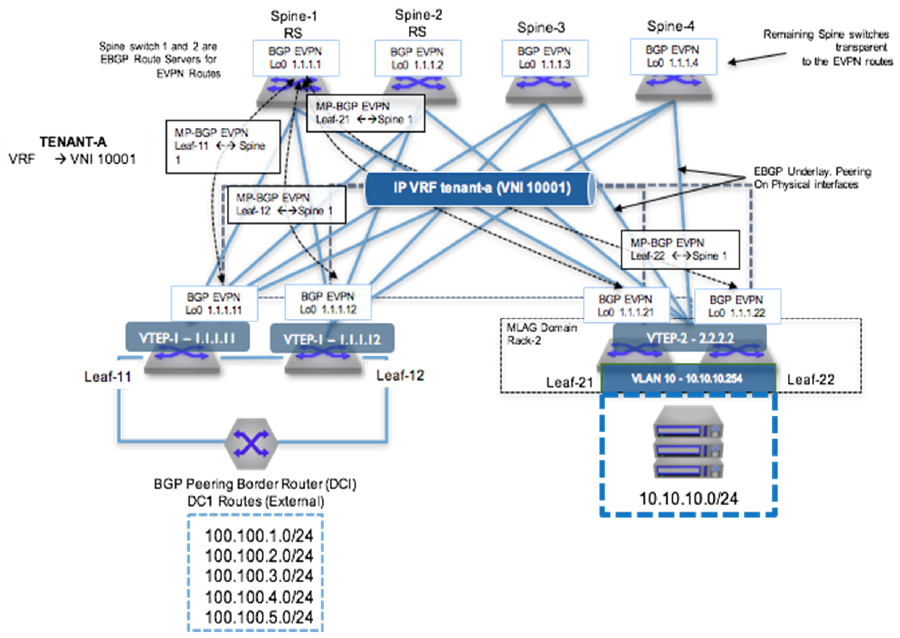
To provide VXLAN routing and bridging between the two MLAG domains, each leaf switch is evpn peering with the four spine switches via a loopback interface.
eBGP Underlay Configuration: Leaf-11
Underlay configuration is straightforward and all neighbors are eBGP. Since all leaves share the same AS number, the allowas-in command was added in the leaf.
interface Ethernet1
   description Spine-1-et1/1
   mtu 9214
   no switchport
   ip address 172.168.1.1/31

interface Ethernet8/1
   description ck428-et8/1
   speed forced 40gfull
   no switchport
   ip address 172.168.1.10/31

interface Loopback0
   ip address 1.1.1.11/32

ip prefix-list loopback
   seq 10 permit 1.1.1.0/24 ge 24
!
route-map loopback permit 10
   match ip address prefix-list loopback

router bgp 65004
neighbor SPINE peer-group
   neighbor SPINE remote-as 65001
   neighbor SPINE allowas-in 1
   neighbor SPINE soft-reconfiguration inbound all
   neighbor SPINE send-community
   neighbor 172.168.1.0 peer-group SPINE
   neighbor 172.168.1.11 remote-as 65003
   redistribute connected route-map loopback
eBGP Underlay Configuration: Spine-1
interface Ethernet1/1
   description Leaf-11-et1
   mtu 9214
   no switchport
   ip address 172.168.1.0/31

interface Loopback0
   ip address 1.1.1.1/32
!
ip prefix-list loopback
   seq 10 permit 1.1.1.0/24 ge 24
!
route-map loopback permit 10
   match ip address prefix-list loopback
!
router bgp 65001
   neighbor 172.168.1.1 remote-as 65004
   redistribute connected route-map loopback
VRF Configuration: Leaf-11
VRF-Blue is configured on all the left leaves. The left leaves have pure Layer 3 interfaces and the right side has SVI 10.
vrf instance VRF-Blue

ip routing vrf VRF-Blue

interface Ethernet36
   no switchport
   vrf VRF-Blue
   ip address 172.168.1.9/31

router bgp 65004
     vrf VRF-Blue
           neighbor 172.168.1.8 remote-as 65005
VRF Configuration: Leaf-21
vlan 10

vrf instance VRF-Blue

ip routing vrf VRF-Blue

interface Vlan10
   vrf VRF-Blue
   ip address virtual 10.10.10.1/24

ip virtual-router mac-address 00:aa:aa:aa:aa:aa

interface Port-Channel3
   switchport mode trunk
   mlag 3
VXLAN Configuration: Leaf-11
Make sure all VTEPs have unique loopback0 addresses to represent unique VTEP identifiers. For every VNI that evpn receives, a dynamic VLAN is allocated, so it is a good practice to keep the same VNI.
interface VXLAN1
   VXLAN source-interface Loopback0
   VXLAN udp-port 4789
   VXLAN vrf VRF-Blue vni 10001
VXLAN Configuration: Leaf-21
interface VXLAN1
   VXLAN source-interface Loopback0
   VXLAN udp-port 4789
   VXLAN vrf VRF-Blue vni 10001
evpn Configuration: Leaf-11
Leaf establishes the evpn neighborship with all four spines for redundancy. evpn neighborship is on the loopback address and the multihop keyword is used. Make sure to disable the IPv4 address family for evpn neighbors.
Since the spine is acting like a route-reflector for evpn routes, make sure to configure the next-hop-unchanged.
router bgp 65004
   neighbor SPINE_evpn peer-group
   neighbor SPINE_evpn remote-as 65001
   neighbor SPINE_evpn update-source Loopback0
   neighbor SPINE_evpn ebgp-multihop 3
   neighbor SPINE_evpn send-community extended
   neighbor SPINE_evpn maximum-routes 12000
   neighbor 1.1.1.1 peer-group SPINE_evpn
   !
   address-family evpn
      neighbor SPINE_evpn activate
   !
   address-family ipv4
      no neighbor SPINE_evpn activate
evpn Configuration: Leaf-21
router bgp 65002
   neighbor SPINE_evpn peer-group
   neighbor SPINE_evpn remote-as 65001
   neighbor SPINE_evpn update-source Loopback0
   neighbor SPINE_evpn allowas-in 1
   neighbor SPINE_evpn ebgp-multihop 3
   neighbor SPINE_evpn send-community extended
   neighbor SPINE_evpn maximum-routes 12000
   neighbor 1.1.1.1 peer-group SPINE_evpn
   !
   address-family evpn
      neighbor SPINE_evpn activate
   !
   address-family ipv4
      no neighbor SPINE_evpn activate
evpn Configuration: Spine-1
router bgp 65004
   neighbor SPINE_evpn peer-group
   neighbor SPINE_evpn remote-as 65001
   neighbor SPINE_evpn update-source Loopback0
   neighbor SPINE_evpn ebgp-multihop 3
   neighbor SPINE_evpn send-community extended
   neighbor SPINE_evpn maximum-routes 12000
   neighbor 1.1.1.1 peer-group SPINE_evpn
   !
   address-family evpn
      neighbor SPINE_evpn activate
   !
   address-family ipv4
      no neighbor SPINE_evpn activate
Advertise VRF Routes in evpn: Leaf-11
By configuring VRF under router-bgp, you are advertising routes from that VRF into evpn using the RD/RT. The remote end can install the route by importing the RT.
Leaf-11 has routes in VRF-Blue learned through eBGP with the neighbor down south. Since the routes are already in BGP VRF table, we do not want to configure the redistribute command.
router bgp 65004
   neighbor SPINE_evpn peer-group
   neighbor SPINE_evpn remote-as 65001
   neighbor SPINE_evpn update-source Loopback0
   neighbor SPINE_evpn ebgp-multihop 3
   neighbor SPINE_evpn send-community extended
   neighbor SPINE_evpn maximum-routes 12000
   neighbor 1.1.1.1 peer-group SPINE_evpn
   !
   address-family evpn
      neighbor SPINE_evpn activate
   !
   address-family ipv4
      no neighbor SPINE_evpn activate
Advertise VRF Routes in evpn: Leaf-21
On the other hand Leaf-21 wants to export the connected SVI into evpn and therefore require redistribute connected command.
router bgp 65002
   neighbor SPINE_evpn peer-group
   neighbor SPINE_evpn remote-as 65001
   neighbor SPINE_evpn update-source Loopback0
   neighbor SPINE_evpn allowas-in 1
   neighbor SPINE_evpn ebgp-multihop 3
   neighbor SPINE_evpn send-community extended
   neighbor SPINE_evpn maximum-routes 12000
   neighbor 1.1.1.1 peer-group SPINE_evpn
   !
   address-family evpn
      neighbor SPINE_evpn activate
   !
   address-family ipv4
      no neighbor SPINE_evpn activate
Multi-Tenant evpn VXLAN IRB Sample Configuration
The following configuration example shows a deployment using both symmetric and asymmetric IRB, with VLAN-based and VLAN-aware bundle services; and eBGP overlay and underlay.
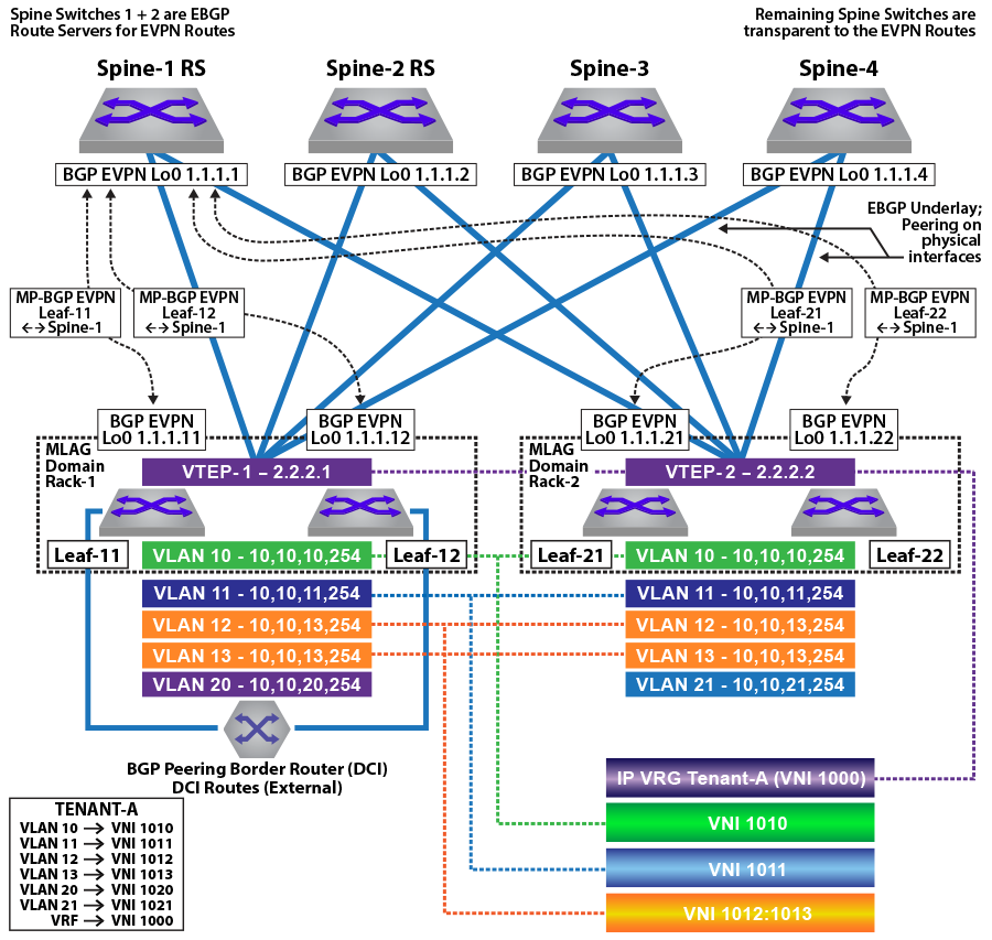
In the symmetric and asymmetric IRB configurations illustrated in the figures above, for Tenant-A, four subnets are stretched across the two MLAG domains with two subnets (VLAN 10, 10.10.10.0/24 and VLAN 11, 10.10.11.0/24) configured as a VLAN-based service and two other subnets (VLAN 12,10.10.12.0/24 and VLAN 13, 10.10.13.0/24) as a VLAN-aware bundle service.
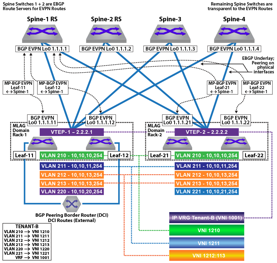
For Tenant-B, four subnets are stretched across the two MLAG domains with two subnets (VLAN 210, 10.10.10.0/24 and VLAN 211,10.10.11.0/24) configured as a VLAN-based service, and two other subnets (VLAN 212,10.10.12.0/24 and VLAN 213,10.10.13.0/24) as a VLAN-aware bundle service.
In addition, each MLAG domain has a single local subnet (Rack-1 subnet 10.10.20.0/24 and Rack-2 subnet 10.10.21.0/24) for the tenant. To provide direct distributed routing, each leaf switch is configured with the same virtual IP address for the four stretched subnets. The virtual IP address is configured in both physical leaf switches of the relevant MLAG domain for the local-only subnets.
For each MLAG domain, a logical VTEP is created with the same shared loopback address. For Rack-1, the logical VTEP IP is 2.2.2.1 and for the Rack-2, the logical VTEP IP is 2.2.2.2. Directly connected to each leaf switch is a host, which is a member of one of the two IP subnets. To provide Layer 2 connectivity across the racks, VXLAN bridging is enabled by mapping VLAN to VNIs as detailed in the diagram.
To provide IP connectivity across all subnets, both stretched and directly connected, an IP-VRF is shared between the two MLAG domains for the tenant. This is used as a transit network to announce and forward the locally attached subnets. Each leaf switch is evpn peering with the four spine switches via a loopback interface on the leaf and again on the spine switches. To provide external connectivity, Leaf-11 and Leaf-12 are eBGP peering via the tenants’ VRFs with the border routers. Both core routers are advertising external prefixes for Internet and any remote site connectivity (default route and IP prefixes from the other DC for the tenant). To provide connectivity within the evpn domain, the leaf switches (Leaf-21 and Leaf-22) re-advertise the prefixes into the tenant’s VRF via a type-5 route advertisement, with a next-hop equal to the advertising VTEP.
MLAG Configuration: Leaf-11 and Leaf-12
Leaf-11 MLAG Configuration
spanning-tree mode mstp
no spanning-tree vlan-id 4093-4094
!
ip virtual-router mac-address mlag-peer
!
vlan 4094
   name MLAG_PEER
   trunk group MLAG
!
vlan 4093
   name LEAF_PEER_L3
   trunk group LEAF_PEER_L3
!
interface Vlan4094
   ip address 172.168.10.1/30
!
interface Port-Channel100
   description port-channel to access switch
    switchport trunk allowed vlan 10-13,20,210-213,220
   switchport mode trunk
   mlag 1
!
interface Port-Channel1000
   switchport mode trunk
   switchport trunk group LEAF_PEER_L3
   switchport trunk group MLAG
!
mlag configuration
   domain-id Rack-1
   local-interface Vlan4094
   peer-address 172.168.10.2
   peer-link Port-Channel1000
Leaf-12 MLAG Configuration
spanning-tree mode mstp
no spanning-tree vlan-id 4093-4094
!
ip virtual-router mac-address mlag-peer
!
vlan 4094
   name MLAG_PEER
   trunk group MLAG
!
vlan 4093
   name LEAF_PEER_L3
   trunk group LEAF_PEER_L3
!
interface Vlan4094
   ip address 172.168.10.2/30
!
interface Port-Channel100
   description port-channel to access switch
    switchport trunk allowed vlan 10-13,20,210-213,220
   switchport mode trunk
   mlag 1
!
interface Port-Channel1000
   switchport mode trunk
   switchport trunk group LEAF_PEER_L3
   switchport trunk group MLAG
!
mlag configuration
   domain-id Rack-1
   local-interface Vlan4094
   peer-address 172.168.10.1
   peer-link Port-Channel1000
MLAG Configuration: Leaf-21 and Leaf-22
Leaf-21 MLAG Configuration
spanning-tree mode mstp
no spanning-tree vlan-id 4093-4094
!
ip virtual-router mac-address mlag-peer
!
vlan 4094
   name MLAG_PEER
   trunk group MLAG
!
vlan 4093
   name LEAF_PEER_L3
   trunk group LEAF_PEER_L3
!
interface Vlan4094
   ip address 172.168.10.1/30
!
interface Port-Channel100
   description port-channel to access switch
  switchport trunk allowed vlan 10-13,21,210-213,220-221
   switchport mode trunk
   mlag 1
!
interface Port-Channel1000
   switchport mode trunk
   switchport trunk group LEAF_PEER_L3
   switchport trunk group MLAG
!
mlag configuration
   domain-id Rack-1
   local-interface Vlan4094
   peer-address 172.168.10.2
   peer-link Port-Channel1000
Leaf-22 MLAG Configuration
spanning-tree mode mstp
no spanning-tree vlan-id 4093-4094
!
ip virtual-router mac-address mlag-peer
!
vlan 4094
   name MLAG_PEER
   trunk group MLAG
!
vlan 4093
   name LEAF_PEER_L3
   trunk group LEAF_PEER_L3
!
interface Vlan4094
   ip address 172.168.10.2/30
!
interface Port-Channel100
   description port-channel to access switch
  switchport trunk allowed vlan 10-13,21,210-213,220-221
   switchport mode trunk
   mlag 1
!
interface Port-Channel1000
   switchport mode trunk
   switchport trunk group LEAF_PEER_L3
   switchport trunk group MLAG
!
mlag configuration
   domain-id Rack-1
   local-interface Vlan4094
   peer-address 172.168.10.1
   peer-link Port-Channel1000hannel1000
VLAN and Distributed IP Address Configuration: Leaf-11 and Leaf-21
VLAN and interface configuration for VLAN 10 (virtual IP address 10.10.10.254) and VLAN 11 (virtual IP address 10.10.11.254), along with SVIs 12, 13, and 20, are similarly configured. To provide multi-tenancy, the two tenant VLANs are placed in a dedicated VRF, named Tenant-A. A further five tenant VLANs are configured and assigned to VRF Tenant-B.
The other VLANs are for peering, MLAG, and a unique VLAN SVI. These VLANs do not use virtual IP addresses.
The tenants’ stretched subnets (Tenant-A: VLANs 10,11,12, and 13; Tenant-B: VLANs 210, 211, 211, 212, and 213) are mapped to unique overlay VXLAN VNIs. The tenants’ IP-VRF (Tenant-A and Tenant-B) is associated with a VNI using the VXLAN vrf command under the VXLAN interface. In the forwarding model for symmetric IRB, this VNI will be used as the transit VNI for routing to subnets not locally configured on the VTEP.
As a standard MLAG configuration, both leaf switches in each MLAG domain share the same logical VTEP IP address. Thus MLAG domain, Rack-1 (Leaf-11 + Leaf-12) has a shared logical VTEP IP of 2.2.2.1 and Rack-2 (Leaf-21 + Leaf-22) has a shared logical VTEP IP of 2.2.2.2.
Leaf-11 VLAN and Distributed IP Address Configuration
!
ip virtual-router mac-address 00:aa:aa:aa:aa:aa
!
vlan 10-11,20,210-211,220,111,2111
!
vlan 12-13
   name VLAN-AWARE-BUNDLE-TENANT-A
!
vlan 212-213
   name VLAN-AWARE-BUNDLE-TENANT-B
!
vrf instance tenant-a
!
vrf instance tenant-b
!
interface lan10
   mtu 9164
   vrf tenant-a
   ip address virtual 10.10.10.254/24
!
interface Vlan11
   mtu 9164
   vrf tenant-a
   ip address virtual 10.10.11.254/24
!
interface Vlan12
   mtu 9164
   vrf tenant-a
   ip address virtual 10.10.12.254/24
!
interface Vlan13
   mtu 9164
   vrf tenant-a
   ip address virtual 10.10.13.254/24
!
interface Vlan20
   mtu 9164
   vrf tenant-a
   ip address virtual 10.10.20.254/24
!
interface Vlan210
   mtu 9164
   vrf tenant-b
   ip address virtual 10.10.10.254/24
!
interface Vlan211
   mtu 9164
   vrf tenant-b
   ip address virtual 10.10.11.254/24
!
interface Vlan212
   mtu 9164
   vrf tenant-b
   ip address virtual 10.10.12.254/24
!
interface Vlan213
   mtu 9164
   vrf tenant-b
   ip address virtual 10.10.13.254/24
!
interface Vlan220
   mtu 9164
   vrf tenant-b
   ip address virtual 10.10.20.254/24
!
interface Vlan1111
   description Unique-highest-IP-in-each-IP-Vrf
   mtu 9164
   vrf tenant-a
   ip address 223.255.255.249/30
!
interface Vlan2111
   description Unique-highest-IP-in-each-IP-Vrf
   mtu 9164
   vrf tenant-b
   ip address 223.255.255.249/30
!
interface Vlan4093
   ip address 172.168.11.1/30
Leaf-21 VLAN and Distributed IP Address Configuration
!
ip virtual-router mac-address 00:aa:aa:aa:aa:aa
!
vlan 10-11,20,210-211,220,111,2111
!
vlan 12-13
   name VLAN-AWARE-BUNDLE-TENANT-A
!
vlan 212-213
   name VLAN-AWARE-BUNDLE-TENANT-B
!
vrf instance tenant-a
!
vrf instance tenant-b
!
interface Vlan10
   mtu 9164
   vrf tenant-a
   ip address virtual 10.10.10.254/24
!
interface Vlan11
   mtu 9164
   vrf tenant-a
   ip address virtual 10.10.11.254/24
!
interface Vlan12
   mtu 9164
   vrf tenant-a
   ip address virtual 10.10.12.254/24
!
interface Vlan13
   mtu 9164
   vrf tenant-a
   ip address virtual 10.10.13.254/24
!
interface Vlan21
   mtu 9164
   vrf tenant-a
   ip address virtual 10.10.21.254/24
!
interface Vlan210
   mtu 9164
   vrf tenant-b
   ip address virtual 10.10.10.254/24
!
interface Vlan211
   mtu 9164
   vrf tenant-b
   ip address virtual 10.10.11.254/24
!
interface Vlan212
   mtu 9164
   vrf tenant-b
   ip address virtual 10.10.12.254/24
!
interface Vlan213
   mtu 9164
   vrf tenant-b
   ip address virtual 10.10.13.254/24
!
interface Vlan221
   mtu 9164
   vrf tenant-b
   ip address virtual 10.10.21.254/24
!
interface Vlan1111
   description Unique-highest-IP-in-each-IP-Vrf
   mtu 9164
   vrf tenant-a
   ip address 223.255.255.253/30
!
interface Vlan2111
   description Unique-highest-IP-in-each-IP-Vrf
   mtu 9164
   vrf tenant-b
   ip address 223.255.255.253/30
!
interface Vlan4093
   ip address 172.168.11.1/30
!
VXLAN Interface Configuration: Leaf-11 and Leaf-21
The tenants’ VLANs are mapped to unique overlay VXLAN VNIs. VLAN 10 is mapped to VNI 1010 on both MLAG domains, and VLAN 11 is mapped to VNI 1011. As standard MLAG configuration, both leaf switches in each MLAG domain share the same logical VTEP IP address. Thus MLAG domain Rack-1 (Leaf-11 + Leaf-12) has a shared logical VTEP IP of 2.2.2.1 and Rack-2 (Leaf-21 + Leaf-22) has a shared logical VTEP IP of 2.2.2.2. Also configured is the VRF-to-VXLAN mapping for Tenant-A.
Leaf-11 VXLAN Interface Configuration
!
interface Loopback1
   ip address 2.2.2.1/32
!
interface VXLAN1
   VXLAN source-interface Loopback1
   VXLAN udp-port 4789
   VXLAN vlan 10 vni 1010
   VXLAN vlan 11 vni 1011
   VXLAN vlan 12 vni 1012
   VXLAN vlan 13 vni 1013
   VXLAN vlan 20 vni 1020
   VXLAN vlan 210 vni 1210
   VXLAN vlan 211 vni 1211
   VXLAN vlan 212 vni 1212
   VXLAN vlan 213 vni 1213
   VXLAN vlan 220 vni 1220
   VXLAN vrf tenant-a vni 1000
   VXLAN vrf tenant-b vni 1001
Leaf-21 VXLAN Interface Configuration
!
interface Loopback1
   ip address 2.2.2.2/32
!
interface VXLAN1
   VXLAN source-interface Loopback1
   VXLAN udp-port 4789
   VXLAN vlan 10 vni 1010
   VXLAN vlan 11 vni 1011
   VXLAN vlan 12 vni 1012
   VXLAN vlan 13 vni 1013
   VXLAN vlan 21 vni 1021
   VXLAN vlan 210 vni 1210
   VXLAN vlan 211 vni 1211
   VXLAN vlan 212 vni 1212
   VXLAN vlan 213 vni 1213
   VXLAN vlan 221 vni 1221
   VXLAN vrf tenant-a vni 1000
VXLAN vrf tenant-b vni 1001hardware tcam
system profile VXLAN-routing
Refer to diagrams for VLAN and SVI assignment to tenant; Leaf-11 also has peering out to the border router in addition to the connected SVIs.
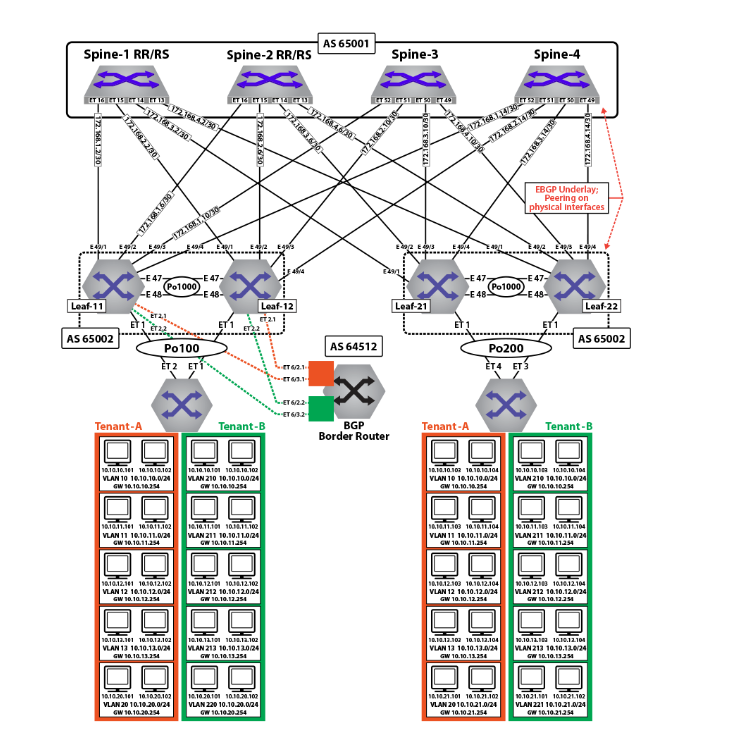
eBGP Underlay Configuration on the Leaf Switches
The leaf switches for the underlay network peer with each spine on the physical interface. For evpn route advertisement, the BGP evpn session is between loopback addresses.
In this case, the underlay is all eBGP, and peering is on the physical interfaces. The MLAG leaves also peer with each other in the underlay to retain BGP evpn connectivity (loopback reachability) in the unlikely case that all spine links are down. This is a failover configuration that can be implemented if there is ever the chance a leaf could be “core isolated.” The configuration can be viewed on each leaf using the command show running-configuration section bgp.
The following examples show the underlay configuration on all four leaf switches, and also on two of the spine switches as an example of the underlay configuration on the spine.
The configuration uses the following peer groups:
SPINE configuration inherited for underlay (eBGP) peering to the spines
SPINE_evpn overlay eBGP peering between spine and leaf, using loopbacks
eBGP Underlay Configuration: Leaf-11
route-map loopback permit 10
   match ip address prefix-list loopback
!
route-map dont_advertise_loopbacks deny 10
   match ip address prefix-list loopback
!
route-map dont_advertise_loopbacks permit 20
!
ip prefix-list loopback
    seq 10 permit 1.1.1.11/32
    seq 20 permit 1.1.1.12/32
    seq 30 permit 1.1.1.22/32
    seq 40 permit 1.1.1.21/32
    seq 50 permit 2.2.2.1/32
    seq 60 permit 2.2.2.2/32
!
router bgp 65002
   router-id 1.1.1.11
   maximum-paths 8 ecmp 16
   neighbor SPINE peer-group
   neighbor SPINE remote-as 65001
   neighbor SPINE allowas-in 1
   neighbor SPINE soft-reconfiguration inbound all
   neighbor SPINE route-map loopback out
   neighbor SPINE send-community
   neighbor 172.168.1.1 peer-group SPINE
   neighbor 172.168.1.5 peer-group SPINE
   neighbor 172.168.1.9 peer-group SPINE
   neighbor 172.168.1.13 peer-group SPINE
   neighbor 172.168.11.2 remote-as 65004
   neighbor 172.168.11.2 local-as 65002 no-prepend replace-as
   neighbor 172.168.11.2 allowas-in 1
   neighbor 172.168.11.2 maximum-routes 12000
   redistribute connected route-map loopback
eBGP Underlay Configuration: Leaf-12
route-map loopback permit 10
   match ip address prefix-list loopback
!
route-map dont_advertise_loopbacks deny 10
   match ip address prefix-list loopback
!
route-map dont_advertise_loopbacks permit 20
!
ip prefix-list loopback
    seq 10 permit 1.1.1.11/32
    seq 20 permit 1.1.1.12/32
    seq 30 permit 1.1.1.22/32
    seq 40 permit 1.1.1.21/32
    seq 50 permit 2.2.2.1/32
    seq 60 permit 2.2.2.2/32
!
router bgp 65002
   router-id 1.1.1.12
   maximum-paths 8 ecmp 16
   neighbor SPINE peer-group
   neighbor SPINE remote-as 65001
   neighbor SPINE allowas-in 1
   neighbor SPINE soft-reconfiguration inbound all
   neighbor SPINE route-map loopback out
   neighbor SPINE send-community
   neighbor 172.168.2.1 peer-group SPINE
   neighbor 172.168.2.5 peer-group SPINE
   neighbor 172.168.2.9 peer-group SPINE
   neighbor 172.168.2.13 peer-group SPINE
   neighbor 172.168.11.1 remote-as 65002
   neighbor 172.168.11.1 local-as 65004 no-prepend replace-as
   neighbor 172.168.11.1 allowas-in 1
   neighbor 172.168.11.1 maximum-routes 12000
   redistribute connected route-map loopback
eBGP Underlay Configuration: Leaf-21
route-map loopback permit 10
   match ip address prefix-list loopback
!
ip prefix-list loopback
    seq 10 permit 1.1.1.11/32
    seq 20 permit 1.1.1.12/32
    seq 30 permit 1.1.1.22/32
    seq 40 permit 1.1.1.21/32
    seq 50 permit 2.2.2.1/32
    seq 60 permit 2.2.2.2/32
!
router bgp 65002
   router-id 1.1.1.21
   maximum-paths 8 ecmp 16
   neighbor SPINE peer-group
   neighbor SPINE remote-as 65001
   neighbor SPINE allowas-in 1
   neighbor SPINE soft-reconfiguration inbound all
   neighbor SPINE route-map loopback out
   neighbor SPINE send-community
   neighbor SPINE maximum-routes 20000
   neighbor 172.168.3.1 peer-group SPINE
   neighbor 172.168.3.5 peer-group SPINE
   neighbor 172.168.3.9 peer-group SPINE
   neighbor 172.168.3.13 peer-group SPINE
   neighbor 172.168.11.2 remote-as 65004
   neighbor 172.168.11.2 local-as 65002 no-prepend replace-as
   neighbor 172.168.11.2 allowas-in 1
   neighbor 172.168.11.2 maximum-routes 12000
   redistribute connected route-map loopback
eBGP Underlay Configuration: Leaf-22
route-map loopback permit 10
   match ip address prefix-list loopback
!
ip prefix-list loopback
    seq 10 permit 1.1.1.11/32
    seq 20 permit 1.1.1.12/32
    seq 30 permit 1.1.1.22/32
    seq 40 permit 1.1.1.21/32
    seq 50 permit 2.2.2.1/32
    seq 60 permit 2.2.2.2/32
!
router bgp 65002
   router-id 1.1.1.22
   maximum-paths 8 ecmp 16
   neighbor SPINE peer-group
   neighbor SPINE remote-as 65001
   neighbor SPINE allowas-in 1
   neighbor SPINE soft-reconfiguration inbound all
   neighbor SPINE route-map loopback out
   neighbor SPINE send-community
   neighbor SPINE maximum-routes 20000
   neighbor 172.168.4.1 peer-group SPINE
   neighbor 172.168.4.5 peer-group SPINE
   neighbor 172.168.4.9 peer-group SPINE
   neighbor 172.168.4.13 peer-group SPINE
   neighbor 172.168.11.1 remote-as 65002
   neighbor 172.168.11.1 local-as 65004 no-prepend replace-as
   neighbor 172.168.11.2 allowas-in 1
   neighbor 172.168.11.1 maximum-routes 12000
   redistribute connected route-map loopback
evpn BGP Configuration on the Spine Switches
The evpn BGP configuration on two of the spine switches is summarized below. Note that only the evpn BGP sessions are listed for the two spine switches: the BGP underlay configuration is not included.
evpn BGP Configuration: Spine-1
route-map loopback permit 10
   match ip address prefix-list loopback
!
ip prefix-list loopback
    seq 10 permit 1.1.1.11/32
    seq 20 permit 1.1.1.12/32
    seq 30 permit 1.1.1.22/32
    seq 40 permit 1.1.1.21/32
    seq 50 permit 2.2.2.1/32
    seq 60 permit 2.2.2.2/32
!
router bgp 65001
   router-id 1.1.1.1
   distance bgp 20 200 200
   maximum-paths 8 ecmp 16
   neighbor LEAF peer-group
   neighbor LEAF remote-as 65002
   neighbor LEAF maximum-routes 20000
   neighbor 172.168.1.2 peer-group LEAF
   neighbor 172.168.2.2 peer-group LEAF
   neighbor 172.168.3.2 peer-group LEAF
   neighbor 172.168.4.2 peer-group LEAF
   redistribute connected route-map loopback
evpn BGP Configuration: Spine-2
route-map loopback permit 10
   match ip address prefix-list loopback
!
ip prefix-list loopback
    seq 10 permit 1.1.1.11/32
    seq 20 permit 1.1.1.12/32
    seq 30 permit 1.1.1.22/32
    seq 40 permit 1.1.1.21/32
    seq 50 permit 2.2.2.1/32
    seq 60 permit 2.2.2.2/32
!
router bgp 65001
   router-id 1.1.1.2
   distance bgp 20 200 200
   maximum-paths 8 ecmp 16
   neighbor LEAF peer-group
   neighbor LEAF remote-as 65002
   neighbor LEAF maximum-routes 20000
   neighbor 172.168.1.6 peer-group LEAF
   neighbor 172.168.2.6 peer-group LEAF
   neighbor 172.168.3.6 peer-group LEAF
   neighbor 172.168.4.6 peer-group LEAF
   redistribute connected route-map loopback
eBGP Overlay on Leaf Switches
The MAC VRFs and IP VRF for the tenants’ subnets are created in the BGP router context with unique Route-Distinguishers (RD) and Route-Targets (RT) attached to each MAC-VRF and IP-VRF. The RDs provide support for overlapping MAC and IP addresses across tenants, while the RTs allow control of the routes imported and exported between MAC VRFs.
To ensure all routes are correctly imported between VTEPs sharing the same Layer-2 domain, the import and export RTs are equal across the two MLAG domains. The redistribute learned statement under each MAC VRF ensures any locally learned MACs in the VLAN are automatically announced as type-2 routes.
The IP VRF (Tenant-A) is created on all leaf switches which have subnets attached to the tenant’s VRF with the same route target ensuring that routes are correctly imported and exported between VTEPs in the VRF. On Leaf-21 and Leaf-22, to import the external routes an eBGP session with the BGP peering router is created under the IP VRF (Tenant-A) context, and a peering from each to the other is created on the overlay.
evpn BGP Overlay Configuration for the Tenants’ MAC VRFs and IP VRF: Leaf-11
route-map loopback permit 10
   match ip address prefix-list loopback
!
route-map dont_advertise_loopbacks deny 10
   match ip address prefix-list loopback
!
route-map dont_advertise_loopbacks permit 20
!
ip prefix-list loopback
    seq 10 permit 1.1.1.11/32
    seq 20 permit 1.1.1.12/32
    seq 30 permit 1.1.1.22/32
    seq 40 permit 1.1.1.21/32
    seq 50 permit 2.2.2.1/32
    seq 60 permit 2.2.2.2/32
!
router bgp 65002
   router-id 1.1.1.11
   maximum-paths 4
   neighbor SPINE_evpn peer-group
   neighbor SPINE_evpn remote-as 65001
   neighbor SPINE_evpn update-source Loopback0
   neighbor SPINE_evpn allowas-in 2
   neighbor SPINE_evpn ebgp-multihop 5
   neighbor SPINE_evpn send-community extended
   neighbor SPINE_evpn maximum-routes 12000
   neighbor 1.1.1.1 peer-group SPINE_evpn
   neighbor 1.1.1.2 peer-group SPINE_evpn
   redistribute connected route-map loopback
   !
  vlan 10
      rd 1.1.1.11:1010
      route-target both 1010:1010
      redistribute learned
   !
   vlan 11
      rd 1.1.1.11:1011
      route-target both 1011:1011
      redistribute learned
   !
   vlan 20
      rd 1.1.1.11:1020
      route-target both 1020:1020
      redistribute learned
   !
   vlan 210
      rd 1.1.1.11:1210
      route-target both 1210:1210
      redistribute learned
      no redistribute host-route
   !
   vlan 211
      rd 1.1.1.11:1211
      route-target both 1211:1211
      redistribute learned
      no redistribute host-route
   !
   vlan 220
      rd 1.1.1.11:1220
      route-target both 1220:1220
      redistribute learned
      no redistribute host-route
   !
  vlan-aware-bundle Tenant-A-VLAN-12-13
      rd 1.1.1.11:1213
      route-target both 12:13
      redistribute learned
      vlan 12-13
   !
   vlan-aware-bundle Tenant-B-VLAN-212-213
       rd 1.1.1.11:21213
       route-target both 212:213
       redistribute learned
       no redistribute host-route
       vlan 212-213
   !
   address-family evpn
      neighbor SPINE_evpn activate
   !
   address-family ipv4
      no neighbor SPINE_evpn activate
   !
   vrf tenant-a
      rd 1.1.1.11:1000
      route-target import 1000:1000
      route-target export 1000:1000
      neighbor 192.168.168.9 remote-as 64512
      neighbor 192.168.168.9 local-as 65002 no-prepend replace-as
      neighbor 192.168.168.9 maximum-routes 12000
      neighbor 223.255.255.250 peer-group LEAF_PEER_OVERLAY
      neighbor 223.255.255.250 remote-as 65004
      neighbor 223.255.255.250 local-as 65002 no-prepend replace-as
      redistribute connected route-map dont_advertise_loopbacks
   !
   vrf tenant-b
      rd 1.1.1.11:1001
      route-target import 1001:1001
      route-target export 1001:1001
      neighbor 192.168.168.21 remote-as 64513
      neighbor 192.168.168.21 local-as 65002 no-prepend replace-as
      neighbor 192.168.168.21 maximum-routes 12000
      neighbor 223.255.255.249 peer-group LEAF_PEER_OVERLAY
      neighbor 223.255.255.249 remote-as 65004
      neighbor 223.255.255.249 local-as 65002 no-prepend replace-as
      redistribute connected route-map dont_advertise_loopbacks
evpn BGP Overlay Configuration for the Tenants’ MAC VRFs and IP VRF: Leaf-12
route-map loopback permit 10
   match ip address prefix-list loopback
!
route-map dont_advertise_loopbacks deny 10
   match ip address prefix-list loopback
!
route-map dont_advertise_loopbacks permit 20
!
ip prefix-list loopback
    seq 10 permit 1.1.1.11/32
    seq 20 permit 1.1.1.12/32
    seq 30 permit 1.1.1.22/32
    seq 40 permit 1.1.1.21/32
    seq 50 permit 2.2.2.1/32
    seq 60 permit 2.2.2.2/32
!
router bgp 65002
   router-id 1.1.1.12
   maximum-paths 4
   neighbor SPINE_evpn peer-group
   neighbor SPINE_evpn remote-as 65001
   neighbor SPINE_evpn update-source Loopback0
   neighbor SPINE_evpn allowas-in 2
   neighbor SPINE_evpn ebgp-multihop 5
   neighbor SPINE_evpn send-community extended
   neighbor SPINE_evpn maximum-routes 12000
   neighbor 1.1.1.1 peer-group SPINE_evpn
   neighbor 1.1.1.2 peer-group SPINE_evpn
   redistribute connected route-map loopback
!
  vlan 10
      rd 1.1.1.12:1010
      route-target both 1010:1010
      redistribute learned
   !
   vlan 11
      rd 1.1.1.12:1011
      route-target both 1011:1011
      redistribute learned
   !
   vlan 20
      rd 1.1.1.12:1020
      route-target both 1020:1020
      redistribute learned
   !
   vlan 210
      rd 1.1.1.12:1210
      route-target both 1210:1210
      redistribute learned
      no redistribute host-route
   !
   vlan 211
      rd 1.1.1.12:1211
      route-target both 1211:1211
      redistribute learned
      no redistribute host-route
   !
   vlan 220
      rd 1.1.1.12:1220
      route-target both 1220:1220
      redistribute learned
      no redistribute host-route
   !
   vlan-aware-bundle Tenant-A-VLAN-12-13
      rd 1.1.1.12:1213
      route-target both 12:13
      redistribute learned
      vlan 12-13
   !
   vlan-aware-bundle Tenant-B-VLAN-212-213
      rd 1.1.1.12:21213
      route-target both 212:213
      redistribute learned
      no redistribute host-route
      vlan 212-213
   !
   address-family evpn
      neighbor SPINE_evpn activate
   !
   address-family ipv4
      no neighbor SPINE_evpn activate
   !
   vrf tenant-a
      rd 1.1.1.12:1000
      route-target import 1000:1000
      route-target export 1000:1000
      neighbor 192.168.168.13 remote-as 64512
      neighbor 192.168.168.13 local-as 65002 no-prepend replace-as
      neighbor 192.168.168.13 maximum-routes 12000
      neighbor 223.255.255.249 peer-group LEAF_PEER_OVERLAY
      neighbor 223.255.255.249 remote-as 65002
      neighbor 223.255.255.249 local-as 65004 no-prepend replace-as
      redistribute connected route-map dont_advertise_loopbacks
   !
   vrf tenant-b
      rd 1.1.1.12:1001
      route-target import 1001:1001
      route-target export 1001:1001
      neighbor 192.168.168.23 remote-as 64513
      neighbor 192.168.168.23 local-as 65002 no-prepend replace-as
      neighbor 192.168.168.23 maximum-routes 12000
      neighbor 223.255.255.249 peer-group LEAF_PEER_OVERLAY
      neighbor 223.255.255.249 remote-as 65002
      neighbor 223.255.255.249 local-as 65004 no-prepend replace-as
      redistribute connected route-map dont_advertise_loopbacks
evpn BGP Overlay Configuration for the Tenants’ MAC VRFs and IP VRF: Leaf-21
route-map loopback permit 10
   match ip address prefix-list loopback
!
route-map dont_advertise_loopbacks deny 10
   match ip address prefix-list loopback
!
route-map dont_advertise_loopbacks permit 20
!
router bgp 65002
   router-id 1.1.1.21
   maximum-paths 4
   neighbor SPINE_evpn peer-group
   neighbor SPINE_evpn remote-as 65001
   neighbor SPINE_evpn update-source Loopback0
   neighbor SPINE_evpn allowas-in 2
   neighbor SPINE_evpn ebgp-multihop 5
   neighbor SPINE_evpn send-community extended
   neighbor SPINE_evpn maximum-routes 12000
   neighbor 1.1.1.1 peer-group SPINE_evpn
   neighbor 1.1.1.2 peer-group SPINE_evpn
   redistribute connected route-map loopback
   !
   vlan 10
      rd 1.1.1.21:1010
      route-target both 1010:1010
      redistribute learned
   !
   vlan 11
      rd 1.1.1.21:1011
      route-target both 1011:1011
      redistribute learned
   !
   vlan 21
      rd 1.1.1.21:1021
      route-target both 1021:1021
      redistribute learned
   !
   vlan 210
      rd 1.1.1.21:1210
      route-target both 1210:1210
      redistribute learned
      no redistribute host-route
   !
   vlan 211
      rd 1.1.1.21:1211
      route-target both 1211:1211
      redistribute learned
      no redistribute host-route
   !
   vlan 221
      rd 1.1.1.21:1221
      route-target both 1221:1221
      redistribute learned
      no redistribute host-route
   !
   vlan-aware-bundle Tenant-A-VLAN-12-13
      rd 1.1.1.21:1213
      route-target both 12:13
      redistribute learned
      vlan 12-13
   !
   vlan-aware-bundle Tenant-B-VLAN-212-213
      rd 1.1.1.21:21213
      route-target both 212:213
      redistribute learned
      redistribute host-route
      vlan 212-213
   !
   address-family evpn
      neighbor SPINE_evpn activate
   !
   address-family ipv4
      no neighbor SPINE_evpn activate
   !
   vrf tenant-a
      rd 1.1.1.21:1000
      route-target import 1000:1000
      route-target export 1000:1000
      neighbor 223.255.255.254 remote-as 65002
      neighbor 223.255.255.254 next-hop-self
      neighbor 223.255.255.254 update-source Vlan1111
      neighbor 223.255.255.254 allowas-in 1
      neighbor 223.255.255.254 maximum-routes 12000
      redistribute connected route-map dont_advertise_loopbacks
   !
   vrf tenant-b
      rd 1.1.1.21:1001
      route-target import 1001:1001
      route-target export 1001:1001
      neighbor 223.255.255.254 remote-as 65002
      neighbor 223.255.255.254 next-hop-self
      neighbor 223.255.255.254 update-source Vlan2111
      neighbor 223.255.255.254 allowas-in 1
      neighbor 223.255.255.254 maximum-routes 12000
      redistribute connected route-map dont_advertise_loopbacks
evpn BGP Overlay Configuration for the Tenants’ MAC VRFs and IP VRF: Leaf-22
route-map loopback permit 10
   match ip address prefix-list loopback
!
route-map dont_advertise_loopbacks deny 10
   match ip address prefix-list loopback
!
route-map dont_advertise_loopbacks permit 20
!
router bgp 65002
   router-id 1.1.1.22
   maximum-paths 4
   neighbor SPINE_evpn peer-group
   neighbor SPINE_evpn remote-as 65001
   neighbor SPINE_evpn update-source Loopback0
   neighbor SPINE_evpn allowas-in 2
   neighbor SPINE_evpn ebgp-multihop 5
   neighbor SPINE_evpn send-community extended
   neighbor SPINE_evpn maximum-routes 12000
   neighbor 1.1.1.1 peer-group SPINE_evpn
   neighbor 1.1.1.2 peer-group SPINE_evpn
   redistribute connected route-map loopback
   !
   vlan 10
      rd 1.1.1.22:1010
      route-target both 1010:1010
      redistribute learned
   !
   vlan 11
      rd 1.1.1.22:1011
      route-target both 1011:1011
      redistribute learned
   !
   vlan 21
      rd 1.1.1.22:1021
      route-target both 1021:1021
      redistribute learned
   !
   vlan 210
      rd 1.1.1.22:1210
      route-target both 1210:1210
      redistribute learned
      no redistribute host-route
   !
   vlan 211
      rd 1.1.1.22:1211
      route-target both 1211:1211
      redistribute learned
      no redistribute host-route
   !
   vlan 221
      rd 1.1.1.22:1221
      route-target both 1221:1221
      redistribute learned
      no redistribute host-route
   !
   vlan-aware-bundle Tenant-A-VLAN-12-13
      rd 1.1.1.22:1213
      route-target both 12:13
      redistribute learned
      vlan 12-13
   !
   vlan-aware-bundle Tenant-B-VLAN-212-213
      rd 1.1.1.22:21213
      route-target both 212:213
      redistribute learned
      no redistribute host-route
      vlan 212-213
   !
   address-family evpn
      neighbor SPINE_evpn activate
   !
   address-family ipv4
      no neighbor SPINE_evpn activate
   !
   vrf tenant-a
      rd 1.1.1.22:1000
      route-target import 1000:1000
      route-target export 1000:1000
      neighbor 223.255.255.253 remote-as 65002
      neighbor 223.255.255.253 next-hop-self
      neighbor 223.255.255.253 update-source Vlan1111
      neighbor 223.255.255.253 allowas-in 1
      neighbor 223.255.255.253 maximum-routes 12000
      redistribute connected route-map dont_advertise_loopbacks
   !
   vrf tenant-b
      rd 1.1.1.22:1001
      route-target import 1001:1001
      route-target export 1001:1001
      neighbor 223.255.255.253 remote-as 65002
      neighbor 223.255.255.253 next-hop-self
      neighbor 223.255.255.253 update-source Vlan2111
      neighbor 223.255.255.253 allowas-in 1
      neighbor 223.255.255.253 maximum-routes 12000
      redistribute connected route-map dont_advertise_loopbacks
eBGP Overlay on Spine Switches
The evpn BGP configuration on the spine switches is summarised in the following examples. Note that only the evpn BGP sessions are listed for two spine switches; the BGP underlay configuration is not included.
evpn BGP Overlay Configuration: Spine-1
!
router bgp 65001
   router-id 1.1.1.1
   distance bgp 20 200 200
   maximum-paths 8 ecmp 16
   neighbor LEAF_evpn peer-group
   neighbor LEAF_evpn remote-as 65002
   neighbor LEAF_evpn update-source Loopback0
   neighbor LEAF_evpn ebgp-multihop 5
   neighbor LEAF_evpn send-community extended
   neighbor LEAF_evpn next-hop-unchanged
   neighbor LEAF_evpn maximum-routes 12000
   neighbor 1.1.1.11 peer-group LEAF_evpn
   neighbor 1.1.1.12 peer-group LEAF_evpn
   neighbor 1.1.1.21 peer-group LEAF_evpn
   neighbor 1.1.1.22 peer-group LEAF_evpn
   !
   address-family evpn
      neighbor LEAF_evpn activate
   !
   address-family ipv4
      no neighbor LEAF_evpn activate
!
   address-family ipv6
      no neighbor LEAF_evpn activate
!
evpn BGP Overlay Configuration: Spine-2
!
router bgp 65001
   router-id 1.1.1.2
   distance bgp 20 200 200
   maximum-paths 8 ecmp 16
   neighbor LEAF_evpn peer-group
   neighbor LEAF_evpn remote-as 65002
   neighbor LEAF_evpn update-source Loopback0
   neighbor LEAF_evpn ebgp-multihop 5
   neighbor LEAF_evpn send-community extended
   neighbor LEAF_evpn next-hop-unchanged
   neighbor LEAF_evpn maximum-routes 12000
   neighbor 1.1.1.11 peer-group LEAF_evpn
   neighbor 1.1.1.12 peer-group LEAF_evpn
   neighbor 1.1.1.21 peer-group LEAF_evpn
   neighbor 1.1.1.21 peer-group LEAF_evpn
   !
   address-family evpn
      neighbor LEAF_evpn activate
   !
   address-family ipv4
      no neighbor LEAF_evpn activate
!
   address-family ipv6
      no neighbor LEAF_evpn activate
!
Symmetric IRB Configuration (Tenant-A)
In symmetric IRB, the host routes are generated by advertising type-2 routes with both the MAC VRF VNI and the routing (or VRF) VNI. On Leaf-11, the MAC VRFs for Tenant-A are left in their default configuration (i.e., redistributing host routes). The following example shows the configuration for the MAC VRF.
MAC VRF Configuration for Tenant-A: Leaf-11
The redistribute learned commands below cause type-2 routes to be advertised with two labels: in VLAN 10, 1010 and 1000; in VLAN 11, 1011 and 1000; in VLAN 21, 1021 and 1000.
vlan 10
      rd 1.1.1.11:1010
      route-target both 1010:1010
      redistribute learned
!
   vlan 11
      rd 1.1.1.11:1011
      route-target both 1011:1011
      redistribute learned
!
   vlan 21
      rd 1.1.1.11:1021
      route-target both 1021:1021
      redistribute learned
   !
With this configuration, any locally learned MAC-IP binding on a leaf switch will be advertised as a type-2 route with two labels. For example, on switches Leaf-21 and Leaf-22, any MAC-IP binding locally learned on subnets 10.10.10.0/24, 10.10.11.0/24, or 10.10.21.0/24 will be advertised as type-2 routes with two labels (the MAC VRF of 1010, 1011, or 1021 and the IP VRF of 1000) and two route targets equal to the relevant MAC VRF for the host and IP VRF for the tenant (1000:1000). The remote leaf switches (Leaf-11 and Leaf-12), will now learn the host route in the IP VRF.
In addition to advertising the type-2 routes with dual labels, the switch will still advertise type-5 routes. This ensures connectivity to the remote subnet even when no host on the subnet has been learned. With both a layer-2 route and layer-3 host route for Server-3 learned on the MAC VRF(1010) and the IP VRF (1000) on Leaf-11, traffic ingressing on Leaf-11 from the local subnet 10.10.10.103 (i.e., VLAN 10) will be VXLAN bridged based on the MAC VRF entry. Traffic ingressing from outside the subnet (i.e., VLAN 11, 12, 13, or 20) will be routed to the host via the IP VRF host route.
The VLAN-aware bundle VLAN type-2 routes are advertised with the VNI ID within the update.
The type-5 routes are advertised with the IP VRF Route Distinguisher and the VNI label, signifying that the forwarding path for the prefix would be the IP VRF. The imported routes from the eBGP peering with the BGP border router in Leaf-11 and Leaf-12 are imported by both switches, and redistributed via type-5 advertisements to Leaf-21 and Leaf-22.
Asymmetric IRB Configuration (Tenant-B)
In asymmetric IRB, the host routes are generated by advertising type-2 routes with just the MAC VRF VNI. On leaf 11, the MAC VRFs for Tenant-B are configured with no redistribute host route within the MAC VRF configuration. The following example shows the configuration for the MAC VRF.
MAC VRF Configuration for Tenant-B: Leaf-11
The no redistribute host-route commands below cause type-2 routes to be advertised with a single label: in VLAN 210, 1110; in VLAN 211, 1211; in VLAN 220, 1220; and in the VLAN-aware bundle (Tenant-B-VLAN-212-213), 1212 and 1213.
vlan 210
      rd 1.1.1.11:1210
      route-target both 1210:1210
      redistribute learned
      no redistribute host-route
   !
   vlan 211
      rd 1.1.1.11:1211
      route-target both 1211:1211
      redistribute learned
      no redistribute host-route
   !
   vlan 220
      rd 1.1.1.11:1220
      route-target both 1220:1220
      redistribute learned
      no redistribute host-route
!
     vlan-aware-bundle Tenant-B-VLAN-212-213
      rd 1.1.1.11:21213
      route-target both 212:213
      redistribute learned
      no redistribute host-route
      vlan 212-213
   !
With this configuration, any locally learned MAC-IP binding on a leaf switch will be advertised as a type-2 route with a single label. For example, on Leaf-11 and Leaf-12, any MAC-IP binding locally learned on subnets 10.10.10.0/24, 10.10.11.0/24, or 10.10.21.0/24 will be advertised as type-2 routes with a single label, the MAC VRF (1210, 1211, 1220, 1212, 1213, or 21111). The IP VRF (1001) still advertises the type-5 prefix routes. This ensures connectivity to the remote subnet even when no host on the subnet has been learned.
The VLAN-aware bundle VLAN type-2 routes are advertised with the VNI ID within the update.
evpn MPLS Sample Configuration
This section describes configuring and verifying BGP VPN, which has steps similar to the evpn VXLAN demonstration. Here, we examine BGP evpn layer 3 VPN over LDP, Segment Routing (ISIS-SR), and BGP-SR transport LSPs. This highlights the difference between the transport and the VPN overlay service.
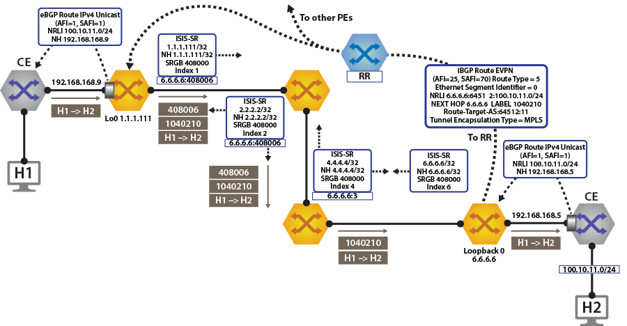
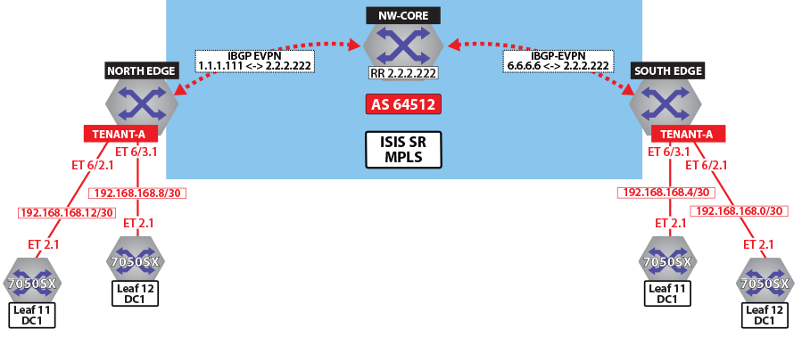
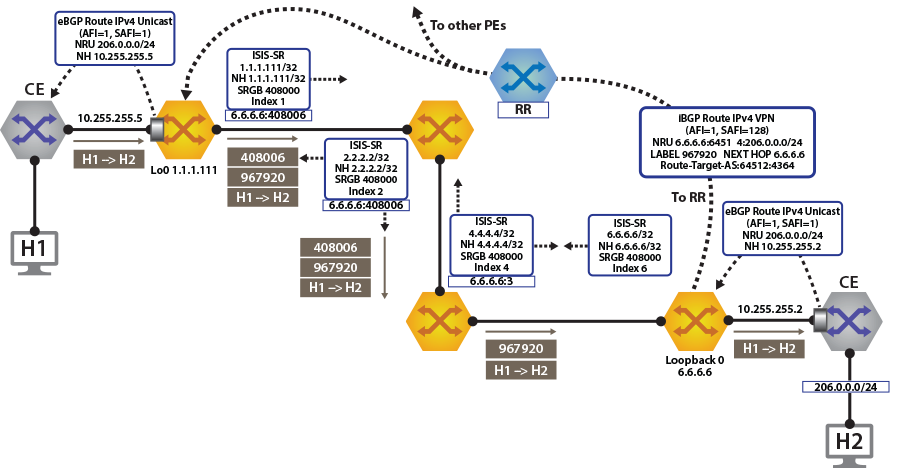
Layer 3 VPN Over ISIS-SR
The following figures illustrate the overview of combined control and data planes.
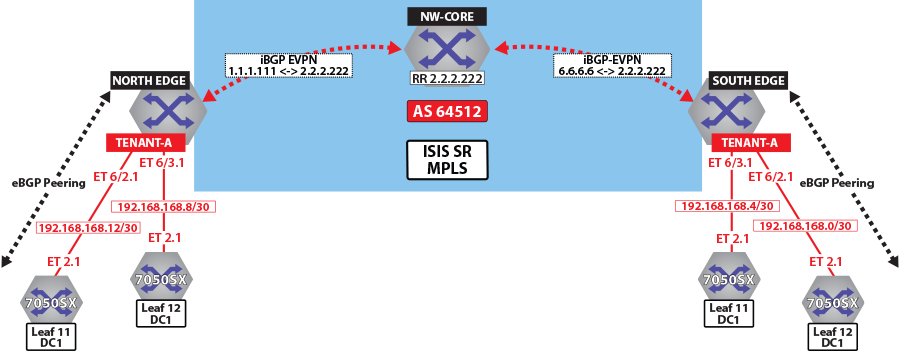
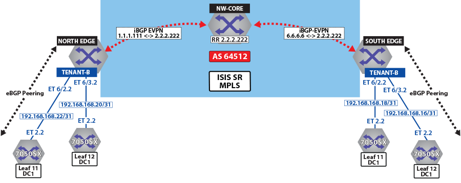
The North Edge router has an eBGP peering session out to Leaf-11 and Leaf-12 in DC1, while the South Edge router has peerings to Leaf-11 andLeaf-12 in DC2. Tenant-a has few additional local interfaces used for testing.
Example
The show ip route vrf tenant-a connected command displays the interfaces assigned to the tenant-a of North Edge router.
north-edge# show ip route vrf tenant-a connected

VRF: tenant-a
Codes: C - connected, S - static, K - kernel,
       O - OSPF, IA - OSPF inter area, E1 - OSPF external type 1,
       E2 - OSPF external type 2, N1 - OSPF NSSA external type 1,
       N2 - OSPF NSSA external type2, B I - iBGP, B E - eBGP,
       R - RIP, I L1 - IS-IS level 1, I L2 - IS-IS level 2,
       O3 - OSPFv3, A B - BGP Aggregate, A O - OSPF Summary,
       NG - Nexthop Group Static Route, V - VXLAN Control Service,
       DH - DHCP client installed default route, M - Martian,
       DP - Dynamic Policy Route

 C      192.168.168.8/30 is directly connected, Ethernet6/3.1
 C      192.168.168.12/30 is directly connected, Ethernet6/2.1
Activating evpn
In all scenarios, the evpn must be activated under BGP and neighbors configured to exchange Layer 2 VPN/evpn NLRI. The tenant’s VRF (tenant-a and tenant-b) is associated with a dynamically assigned label by BGP.
- Enables the multi-agent routing protocol model, which is required for evpn support.
- Sets the local autonomous system number to 64512 and configures IBGP neighbors that are activated for the Layer 2 VPN/evpn address family.
- Sets the evpn encapsulation type to MPLS.
- Specifies that Loopback0 will be used as the next-hop for all advertised evpn routes. The underlay configuration must provide MPLS LSPs from remote PEs to this loopback interface address.
Example
service routing protocols model multi-agent

router bgp 64512
   router-id 1.1.1.111
   maximum-paths 128 ecmp 128
   neighbor 2.2.2.222 remote-as 64512
   neighbor 2.2.2.222 update-source Loopback0
   neighbor 2.2.2.222 bfd
   neighbor 2.2.2.222 send-community extended
   !
   address-family evpn
     neighbor default encapsulation mpls next-hop-self source-interface Loopback0
       neighbor default graceful-restart
       neighbor 2.2.2.222 activate
   !
Layer 3 Overlay Configuration
Distribution of layer 3 routes over BGP is enabled by configuring one or more IP VRFs under the router bgp configuration mode. Additionally, IP routing must be enabled in the VRF.
The VRF is assigned a unique Route-Distinguisher (RD). The RD allows the PE to advertise evpn routes for the same IP prefix that have been exported by different VRFs. The NLRI RouteKey of a route exported from the VRF’s IPv4 table into evpn consists of both the RD and the original IP prefix.
The Route-Target (RT) extended communities for the VRF. The RTs are associated with all routes exported from the VRF. Received evpn type-5 routes carrying at least one RT matching the VRFs configuration are imported into the VRF. The route target directives are configured under the IPv4 or IPv6 address- family.
Example
vrf tenant-a
      rd 1.1.1.1:64512
      route-target import evpn 64512:11
      route-target export evpn 64512:11
      router-id 1.1.1.111
      neighbor 192.168.168.10 remote-as 65002
      neighbor 192.168.168.10 local-as 64512 no-prepend replace-as
      neighbor 192.168.168.10 default-originate
      neighbor 192.168.168.10 maximum-routes 12000
      neighbor 192.168.168.14 remote-as 65002
      neighbor 192.168.168.14 local-as 64512 no-prepend replace-as
      neighbor 192.168.168.14 default-originate
      neighbor 192.168.168.14 maximum-routes 12000
      redistribute connected
      redistribute static
   !
   vrf tenant-b
      rd 1.1.1.1:64513
      route-target import evpn 64513:11
      route-target export evpn 64513:11
      router-id 1.1.1.111
      neighbor 192.168.168.20 remote-as 65002
      neighbor 192.168.168.20 local-as 64513 no-prepend replace-as
      neighbor 192.168.168.20 maximum-routes 12000
      neighbor 192.168.168.22 remote-as 65002
      neighbor 192.168.168.22 local-as 64513 no-prepend replace-as
      neighbor 192.168.168.22 maximum-routes 12000
      redistribute connected
      redistribute static
   !
Verifying BGP evpn Layer 3 VPN
Show commands are executed in the North Edge router to view routes to the South Edge router. Execute the same commands in the South Edge router to view vice-versa routes.
- The show bgp evpn summary command displays the status of
evpn peers in North Edge
router.
north-edge# show bgp evpn summary BGP summary information for VRF default Router identifier 1.1.1.111, local AS number 64512 Neighbor Status Codes: m - Under maintenance Neighbor V AS MsgRcvd MsgSent InQ OutQ Up/Down State PfxRcd PfxAcc 2.2.2.222 4 64512 195 127 0 0 01:13:31 Estab 78 78 - The show bgp evpn route-type ip-prefix ipv4 next-hop 6.6.6.6
command displays all BGP evpn ip prefix routes received from the South Edge router
(6.6.6.6). Not all are advertised via the RR
2.2.2.222.Note: Each entry in the table represents a BGP path. The path specific information includes Route-Distinguisher and IP prefix. Paths are either received from evpn peers or exported from local VRFs.
north-edge# show bgp evpn route-type ip-prefix ipv4 next-hop 6.6.6.6 BGP routing table information for VRF default Router identifier 1.1.1.111, local AS number 64512 Route status codes: s - suppressed, * - valid, > - active, # - not installed, E - ECMP head, e - ECMP S - Stale, c - Contributing to ECMP, b - backup % - Pending BGP convergence Origin codes: i - IGP, e - EGP, ? - incomplete AS Path Attributes: Or-ID - Originator ID, C-LST - Cluster List, LL Nexthop - Link Local Nexthop Network Next Hop Metric LocPref Weight Path * > RD: 6.6.6.6:64512 ip-prefix 0.0.0.0/0 6.6.6.6 0 100 0 ? Or-ID: 6.6.6.6 C-LST: 2.2.2.222 * > RD: 6.6.6.6:64513 ip-prefix 0.0.0.0/0 6.6.6.6 0 100 0 ? Or-ID: 6.6.6.6 C-LST: 2.2.2.222 * > RD: 6.6.6.6:64514 ip-prefix 10.255.255.0/30 6.6.6.6 - 100 0 65010 i Or-ID: 6.6.6.6 C-LST: 2.2.2.222 * > RD: 6.6.6.6:64512 ip-prefix 100.10.10.0/24 6.6.6.6 - 100 0 65006 i Or-ID: 6.6.6.6 C-LST: 2.2.2.222 * > RD: 6.6.6.6:64513 ip-prefix 100.10.10.0/24 6.6.6.6 - 100 0 65006 i Or-ID: 6.6.6.6 C-LST: 2.2.2.222 * > RD: 6.6.6.6:64512 ip-prefix 100.10.10.103/32 6.6.6.6 - 100 0 65006 65005 65006 i Or-ID: 6.6.6.6 C-LST: 2.2.2.222 * > RD: 6.6.6.6:64512 ip-prefix 100.10.10.104/32 6.6.6.6 - 100 0 65006 65005 65006 i Or-ID: 6.6.6.6 C-LST: 2.2.2.222 * > RD: 6.6.6.6:64512 ip-prefix 100.10.11.0/24 6.6.6.6 - 100 0 65006 i Or-ID: 6.6.6.6 C-LST: 2.2.2.222 * > RD: 6.6.6.6:64513 ip-prefix 100.10.11.0/24 6.6.6.6 - 100 0 65006 i Or-ID: 6.6.6.6 C-LST: 2.2.2.222 * > RD: 6.6.6.6:64512 ip-prefix 100.10.11.103/32 6.6.6.6 - 100 0 65006 65005 65006 i Or-ID: 6.6.6.6 C-LST: 2.2.2.222 * > RD: 6.6.6.6:64512 ip-prefix 100.10.11.104/32 6.6.6.6 - 100 0 65006 65005 65006 i Or-ID: 6.6.6.6 C-LST: 2.2.2.222 - The show bgp evpn route-type ip-prefix 100.10.11.0/24 detail
command displays a detailed view of the IP prefix route for
100.10.11.0/24. The output again includes the RD and IP
prefix identifying the route. As seen above the route is received from the route
reflector, and the VPN label for tenant-a is
958810.
north-edge# show bgp evpn route-type ip-prefix 100.10.11.0/24 detail
BGP routing table information for VRF default
Router identifier 1.1.1.111, local AS number 64512
BGP routing table entry for ip-prefix 100.10.11.0/24, Route Distinguisher: 6.6.6.6:64512
 Paths: 1 available
  65006
    6.6.6.6 from 2.2.2.222 (2.2.2.222)
      Origin IGP, metric -, localpref 100, weight 0, valid, internal, best
      Extended Community: Route-Target-AS:64512:11 TunnelEncap:tunnelTypeMpls
      MPLS label: 958810
BGP routing table entry for ip-prefix 100.10.11.0/24, Route Distinguisher: 6.6.6.6:64513
 Paths: 1 available
  65006
    6.6.6.6 from 2.2.2.222 (2.2.2.222)
      Origin IGP, metric -, localpref 100, weight 0, valid, internal, best
      Extended Community: Route-Target-AS:64513:11 TunnelEncap:tunnelTypeMpls
      MPLS label: 953372
Note: Tenant-a and tenant-b share the same route. Therefore, both route with RD 6.6.6.6:64513 and RT 64513:11. - The show ip bgp vrf tenant-a command displays the BGP table
for VRF in tenant-a containing imported evpn routes. Each entry in the table represent a
BGP path that is either locally redistributed / received into the VRF or imported from
the evpn table.
north-edge# show ip bgp vrf tenant-a
BGP routing table information for VRF tenant-a
Router identifier 1.1.1.111, local AS number 64512
Route status codes: s - suppressed, * - valid, > - active, # - not installed, E - ECMP head, e - ECMP
                    S - Stale, c - Contributing to ECMP, b - backup, L - labeled-unicast
                    % - Pending BGP convergence
Origin codes: i - IGP, e - EGP, ? - incomplete
AS Path Attributes: Or-ID - Originator ID, C-LST - Cluster List, LL Nexthop - Link Local Nexthop

         Network             Next Hop         Metric  LocPref Weight Path
 * >     0.0.0.0/0           6.6.6.6          0       100     0      ? Or-ID: 6.6.6.6 C-LST: 2.2.2.222
 * >Ec   10.10.10.0/24       192.168.168.14   -       100     0      65002 i
 *  ec   10.10.10.0/24       192.168.168.10   -       100     0      65002 i
 * >Ec   10.10.10.103/32     192.168.168.14   -       100     0      65002 i
 *  ec   10.10.10.103/32     192.168.168.10   -       100     0      65002 i
 * >Ec   10.10.10.104/32     192.168.168.14   -       100     0      65002 i

 * >Ec   10.10.44.1/32       192.168.168.14   -       100     0      65002 i
 *  ec   10.10.44.1/32       192.168.168.10   -       100     0      65002 i
 * >     100.10.10.0/24      6.6.6.6          -       100     0      65006 i Or-ID: 6.6.6.6 C-LST: 2.2.2.222
 * >     100.10.10.103/32    6.6.6.6          -       100     0      65006 65005 65006 i Or-ID: 6.6.6.6
C-LST: 2.2.2.222
 * >     100.10.10.104/32    6.6.6.6          -       100     0      65006 65005 65006 i Or-ID: 6.6.6.6
C-LST: 2.2.2.222
C-LST: 2.2.2.222
 * >     100.10.21.102/32    6.6.6.6          -       100     0      65006 65005 65006 i Or-ID: 6.6.6.6
C-LST: 2.2.2.222
 * >     100.10.30.0/24      6.6.6.6          -       100     0      65006 i Or-ID: 6.6.6.6 C-LST: 2.2.2.222
 * >     100.10.32.0/24      6.6.6.6          -       100     0      65006 i Or-ID: 6.6.6.6 C-LST: 2.2.2.222
 * >     192.168.168.0/30    6.6.6.6          -       100     0      i Or-ID: 6.6.6.6 C-LST: 2.2.2.222
 * >     192.168.168.4/30    6.6.6.6          -       100     0      i Or-ID: 6.6.6.6 C-LST: 2.2.2.222
 * >     192.168.168.8/30    -                -       -       0      i
 *  Ec   192.168.168.8/30    192.168.168.14   -       100     0      65002 i
 *  ec   192.168.168.8/30    192.168.168.10   -       100     0      65002 i
 * >     192.168.168.12/30   -                -       -       0      i
 *  Ec   192.168.168.12/30   192.168.168.14   -       100     0      65002 i
 *  ec   192.168.168.12/30   192.168.168.10   -       100     0      65002 i
 * >     223.255.254.248/30  6.6.6.6          -       100     0      65006 i Or-ID: 6.6.6.6 C-LST: 2.2.2.222
 * >     223.255.254.252/30  6.6.6.6          -       100     0      65006 65005 65006 i Or-ID: 6.6.6.6
C-LST: 2.2.2.222
 * >Ec   223.255.255.248/30  192.168.168.14   -       100     0      65002 i
 *  ec   223.255.255.248/30  192.168.168.10   -       100     0      65002 i
 * >Ec   223.255.255.252/30  192.168.168.14   -       100     0      65002 i
 *  ec   223.255.255.252/30  192.168.168.10   -       100     0      65002 i
Note: evpn routes are received from router 2.2.2.222 C-List (cluster list - basically identifying this route as from a route-reflector) with originating router being 6.6.6.6. - The show ip route vrf tenant-b command displays the BGP
table for VRF in tenant-b containing imported evpn
routes.
north-edge# show ip route vrf tenant-b

VRF: tenant-b
Codes: C - connected, S - static, K - kernel,
       O - OSPF, IA - OSPF inter area, E1 - OSPF external type 1,
       E2 - OSPF external type 2, N1 - OSPF NSSA external type 1,
       N2 - OSPF NSSA external type2, B I - iBGP, B E - eBGP,
       R - RIP, I L1 - IS-IS level 1, I L2 - IS-IS level 2,
       O3 - OSPFv3, A B - BGP Aggregate, A O - OSPF Summary,
       NG - Nexthop Group Static Route, V - VXLAN Control Service,
       DH - DHCP client installed default route, M - Martian,
       DP - Dynamic Policy Route

Gateway of last resort:
 B I    0.0.0.0/0 [200/0] via 6.6.6.6/32, IS-IS SR tunnel index 6, label 953372
                             via 192.168.58.12, Ethernet1/1, label 408006
                             via 192.168.59.12, Ethernet2/1, label 408006

 B E    10.10.10.0/24 [200/0] via 192.168.168.22, Ethernet6/2.2
                              via 192.168.168.20, Ethernet6/3.2

 B E    10.10.21.0/24 [200/0] via 192.168.168.22, Ethernet6/2.2
                              via 192.168.168.20, Ethernet6/3.2
 B I    100.10.10.0/24 [200/0] via 6.6.6.6/32, IS-IS SR tunnel index 6, label 953372
                                  via 192.168.58.12, Ethernet1/1, label 408006
                                  via 192.168.59.12, Ethernet2/1, label 408006

 C      192.168.168.20/31 is directly connected, Ethernet6/3.2
 C      192.168.168.22/31 is directly connected, Ethernet6/2.2
 B I    223.255.254.248/30 [200/0] via 6.6.6.6/32, IS-IS SR tunnel index 6, label 953372
                                      via 192.168.58.12, Ethernet1/1, label 408006
                                      via 192.168.59.12, Ethernet2/1, label 408006
 B I    223.255.254.252/30 [200/0] via 6.6.6.6/32, IS-IS SR tunnel index 6, label 953372
                                      via 192.168.58.12, Ethernet1/1, label 408006
                                      via 192.168.59.12, Ethernet2/1, label 408006
 B E    223.255.255.248/30 [200/0] via 192.168.168.22, Ethernet6/2.2
                                   via 192.168.168.20, Ethernet6/3.2
 B E    223.255.255.252/30 [200/0] via 192.168.168.22, Ethernet6/2.2
                                   via 192.168.168.20, Ethernet6/3.2
Note: If we look at the routes in the VRF for tenant-b, we see that the VPN label has now changed, whilst the transport label for NH 6.6.6.6 is the same. The only difference seen in tenant-b, aside from the different VPN label, is that there are no host-routes in tenant-b because within each DC tenant-b is running in asymmetric mode, therefore no host routes are generated/installed in the IP VRF.
Layer 3 evpn Over LDP
The following figures illustrate an overview of the combined control and data planes.
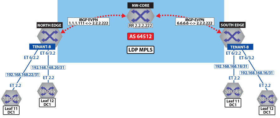
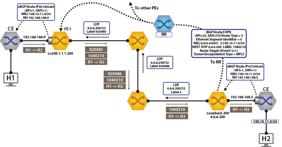
To switch to using the MPLS LDP transport, change the next-hop advertised for evpn routes. As illustrated above, the next hop needs to be set to loopback 200 to use the LDP LSP.
This is achieved by configuring the next-hop for evpn routes on both North Edge and South Edge routes. The output again includes the RD and IP prefixes identifying the route. As seen in the output, we now have the NH set to 6.6.6.200 for tenant-a and tenant-b.
router bgp 64512
   !
   address-family evpn
     neighbor default encapsulation mpls next-hop-self source-interface Loopback200
Once this is configured, we can check the BGP updates and the routes in the VRF.
north-edge# show bgp evpn route-type ip-prefix 100.10.11.0/24 detail
BGP routing table information for VRF default
Router identifier 1.1.1.111, local AS number 64512
BGP routing table entry for ip-prefix 100.10.11.0/24, Route Distinguisher: 6.6.6.6:64512
 Paths: 1 available
  65006
    6.6.6.200 from 2.2.2.222 (2.2.2.222)
      Origin IGP, metric -, localpref 100, weight 0, valid, internal, best
      Extended Community: Route-Target-AS:64512:11 TunnelEncap:tunnelTypeMpls
      MPLS label: 958810
BGP routing table entry for ip-prefix 100.10.11.0/24, Route Distinguisher: 6.6.6.6:64513
 Paths: 1 available
  65006
    6.6.6.200 from 2.2.2.222 (2.2.2.222)
      Origin IGP, metric -, localpref 100, weight 0, valid, internal, best
      Extended Community: Route-Target-AS:64513:11 TunnelEncap:tunnelTypeMpls
MPLS label: 953372Finally, look at the routes in the VRF tenant-a.
north-edge# show ip route vrf tenant-a

VRF: tenant-a
Codes: C - connected, S - static, K - kernel,
       O - OSPF, IA - OSPF inter area, E1 - OSPF external type 1,
       E2 - OSPF external type 2, N1 - OSPF NSSA external type 1,
       N2 - OSPF NSSA external type2, B I - iBGP, B E - eBGP,
       R - RIP, I L1 - IS-IS ----level 1, I L2 - IS-IS level 2,
       O3 - OSPFv3, A B - BGP Aggregate, A O - OSPF Summary,
       NG - Nexthop Group Static Route, V - VXLAN Control Service,
       DH - DHCP client installed default route, M - Martian,
       DP - Dynamic Policy Route

Gateway of last resort:
 B I    0.0.0.0/0 [200/0] via 6.6.6.200/32, LDP tunnel index 1, label 958810
                             via 192.168.58.12, Ethernet1/1, label 904097
                             via 192.168.59.12, Ethernet2/1, label 904098

 B E    10.10.10.103/32 [200/0] via 192.168.168.14, Ethernet6/2.1
                                via 192.168.168.10, Ethernet6/3.1
 B E    10.10.10.104/32 [200/0] via 192.168.168.14, Ethernet6/2.1

                              via 192.168.168.10, Ethernet6/3.1
 B I    100.10.10.103/32 [200/0] via 6.6.6.200/32, LDP tunnel index 1, label 958810
                                    via 192.168.58.12, Ethernet1/1, label 904097
                                    via 192.168.59.12, Ethernet2/1, label 904098

 B I    192.168.168.4/30 [200/0] via 6.6.6.200/32, LDP tunnel index 1, label 958810
                                    via 192.168.58.12, Ethernet1/1, label 904097
                                    via 192.168.59.12, Ethernet2/1, label 904098
 C      192.168.168.8/30 is directly connected, Ethernet6/3.1
 C      192.168.168.12/30 is directly connected, Ethernet6/2.1
 B I    223.255.254.248/30 [200/0] via 6.6.6.200/32, LDP tunnel index 1, label 958810
                                      via 192.168.58.12, Ethernet1/1, label 904097
                                      via 192.168.59.12, Ethernet2/1, label 904098
 B I    223.255.254.252/30 [200/0] via 6.6.6.200/32, LDP tunnel index 1, label 958810
                                      via 192.168.58.12, Ethernet1/1, label 904097
                                      via 192.168.59.12, Ethernet2/1, label 904098
 B E    223.255.255.248/30 [200/0] via 192.168.168.14, Ethernet6/2.1
                                   via 192.168.168.10, Ethernet6/3.1
 B E    223.255.255.252/30 [200/0] via 192.168.168.14, Ethernet6/2.1
via 192.168.168.10, Ethernet6/3.1As a comparison, let us look at the routes for tenant-b.
north-edge# show ip route vrf tenant-b

VRF: tenant-b
Codes: C - connected, S - static, K - kernel,
       O - OSPF, IA - OSPF inter area, E1 - OSPF external type 1,
       E2 - OSPF external type 2, N1 - OSPF NSSA external type 1,
       N2 - OSPF NSSA external type2, B I - iBGP, B E - eBGP,
       R - RIP, I L1 - IS-IS level 1, I L2 - IS-IS level 2,
       O3 - OSPFv3, A B - BGP Aggregate, A O - OSPF Summary,
       NG - Nexthop Group Static Route, V - VXLAN Control Service,
       DH - DHCP client installed default route, M - Martian,
       DP - Dynamic Policy Route

Gateway of last resort:
 B I    0.0.0.0/0 [200/0] via 6.6.6.200/32, LDP tunnel index 1, label 953372
                             via 192.168.58.12, Ethernet1/1, label 904097
                             via 192.168.59.12, Ethernet2/1, label 904098

 B E    10.10.10.0/24 [200/0] via 192.168.168.22, Ethernet6/2.2
                              via 192.168.168.20, Ethernet6/3.2

                              via 192.168.168.20, Ethernet6/3.2
 B I    100.10.10.0/24 [200/0] via 6.6.6.200/32, LDP tunnel index 1, label 953372
                                  via 192.168.58.12, Ethernet1/1, label 904097
                                  via 192.168.59.12, Ethernet2/1, label 904098

                                     via 192.168.59.12, Ethernet2/1, label 904098
 B I    192.168.168.18/31 [200/0] via 6.6.6.200/32, LDP tunnel index 1, label 953372
                                     via 192.168.58.12, Ethernet1/1, label 904097
                                     via 192.168.59.12, Ethernet2/1, label 904098
 C      192.168.168.20/31 is directly connected, Ethernet6/3.2
 C      192.168.168.22/31 is directly connected, Ethernet6/2.2
 B I    223.255.254.248/30 [200/0] via 6.6.6.200/32, LDP tunnel index 1, label 953372
                                      via 192.168.58.12, Ethernet1/1, label 904097
                                      via 192.168.59.12, Ethernet2/1, label 904098
 B I    223.255.254.252/30 [200/0] via 6.6.6.200/32, LDP tunnel index 1, label 953372
                                      via 192.168.58.12, Ethernet1/1, label 904097
                                      via 192.168.59.12, Ethernet2/1, label 904098
 B E    223.255.255.248/30 [200/0] via 192.168.168.22, Ethernet6/2.2
                                   via 192.168.168.20, Ethernet6/3.2
 B E    223.255.255.252/30 [200/0] via 192.168.168.22, Ethernet6/2.2
Layer 3 evpn Over BGP-SR
The following figures illustrate an overview of the combined control and data planes.
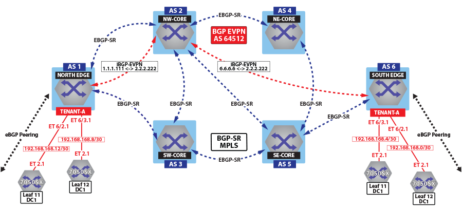
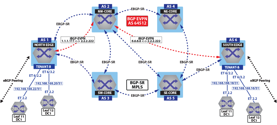
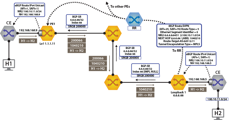
To switch to using the MPLS BGP-SR transport, we need to change the next-hop advertised for the evpn routes. As shown in Control Plane tenant-b Over BGP-SR, the next hop needs to be set to loopback 1 for using the BGP-SR LSP, by configuring the next-hop for the evpn routes.
router bgp 64512
   !
   address-family evpn
     neighbor default encapsulation mpls next-hop-self source-interface Loopback1
Once the next-hop for the evpn routes are configured, we can check the BGP updates and the routes in the VRF. The output again includes the RD and IP prefix identifying the route. As seen in the output, we now have the NH set to 6.6.6.66 for tenant-a and tenant-b.
North Edge.17:52:30# show bgp evpn route-type ip-prefix 100.10.11.0/24 detail

north-edge(config-if-Et2/1)#show bgp evpn route-type ip-prefix 100.10.11.0/24 detail
BGP routing table information for VRF default
Router identifier 1.1.1.111, local AS number 64512
BGP routing table entry for ip-prefix 100.10.11.0/24, Route Distinguisher: 6.6.6.6:64512
 Paths: 1 available
  65006
    6.6.6.66 from 2.2.2.222 (2.2.2.222)
      Origin IGP, metric -, localpref 100, weight 0, valid, internal, best
      Extended Community: Route-Target-AS:64512:11 TunnelEncap:tunnelTypeMpls
      MPLS label: 958810
BGP routing table entry for ip-prefix 100.10.11.0/24, Route Distinguisher: 6.6.6.6:64513
 Paths: 1 available
  65006
    6.6.6.66 from 2.2.2.222 (2.2.2.222)
      Origin IGP, metric -, localpref 100, weight 0, valid, internal, best
      Extended Community: Route-Target-AS:64513:11 TunnelEncap:tunnelTypeMpls
      MPLS label: 953372
Finally, let us look at the routes in the VRF tenant-a.
North Edge.17:55:01# show ip route vrf tenant-a

VRF: tenant-a
Codes: C - connected, S - static, K - kernel,
       O - OSPF, IA - OSPF inter area, E1 - OSPF external type 1,
       E2 - OSPF external type 2, N1 - OSPF NSSA external type 1,
       N2 - OSPF NSSA external type2, B I - iBGP, B E - eBGP,
       R - RIP, I L1 - IS-IS level 1, I L2 - IS-IS level 2,
       O3 - OSPFv3, A B - BGP Aggregate, A O - OSPF Summary,
       NG - Nexthop Group Static Route, V - VXLAN Control Service,
       DH - DHCP client installed default route, M - Martian,
       DP - Dynamic Policy Route

Gateway of last resort:
 B I    0.0.0.0/0 [200/0] via 6.6.6.66/32, BGP LU tunnel index 8, label 958810
                             via 192.168.58.12, Ethernet1/1, label 200066
                             via 192.168.59.12, Ethernet2/1, label 200066

 B E    10.10.10.103/32 [200/0] via 192.168.168.14, Ethernet6/2.1
                                via 192.168.168.10, Ethernet6/3.1
 B E    10.10.10.104/32 [200/0] via 192.168.168.14, Ethernet6/2.1
                                via 192.168.168.10, Ethernet6/3.1

                              via 192.168.168.10, Ethernet6/3.1
 B I    100.10.10.103/32 [200/0] via 6.6.6.66/32, BGP LU tunnel index 8, label 958810
                                    via 192.168.58.12, Ethernet1/1, label 200066
                                    via 192.168.59.12, Ethernet2/1, label 200066

 B I    192.168.168.4/30 [200/0] via 6.6.6.66/32, BGP LU tunnel index 8, label 958810
                                    via 192.168.58.12, Ethernet1/1, label 200066
                                    via 192.168.59.12, Ethernet2/1, label 200066
 C      192.168.168.8/30 is directly connected, Ethernet6/3.1
 C      192.168.168.12/30 is directly connected, Ethernet6/2.1
 B I    223.255.254.248/30 [200/0] via 6.6.6.66/32, BGP LU tunnel index 8, label 958810
                                      via 192.168.58.12, Ethernet1/1, label 200066
                                      via 192.168.59.12, Ethernet2/1, label 200066
 B I    223.255.254.252/30 [200/0] via 6.6.6.66/32, BGP LU tunnel index 8, label 958810
                                      via 192.168.58.12, Ethernet1/1, label 200066
                                      via 192.168.59.12, Ethernet2/1, label 200066
 B E    223.255.255.248/30 [200/0] via 192.168.168.14, Ethernet6/2.1
                                   via 192.168.168.10, Ethernet6/3.1
 B E    223.255.255.252/30 [200/0] via 192.168.168.14, Ethernet6/2.1
                                   via 192.168.168.10, Ethernet6/3.1
As can be seen from the highlighted route above the label stack, the route are the transport labels 958810 and 200066 on top (this is the ECMP label path to reach NH 6.6.6.66), with the tenant-a VPN label 958810 next in the stack, identifying the route as belonging to tenant-a.
As a comparison, look at the routes for tenant-b. As seen in the output, the VPN label assigned to tenant-b is 953372.
north-edge# show bgp evpn route-type ip-prefix 100.10.11.0/24 detail
BGP routing table information for VRF default
Router identifier 1.1.1.111, local AS number 64512
BGP routing table entry for ip-prefix 100.10.11.0/24, Route Distinguisher: 6.6.6.6:64512
 Paths: 1 available
  65006
    6.6.6.66 from 2.2.2.222 (2.2.2.222)
      Origin IGP, metric -, localpref 100, weight 0, valid, internal, best
      Extended Community: Route-Target-AS:64512:11 TunnelEncap:tunnelTypeMpls
      MPLS label: 958810
BGP routing table entry for ip-prefix 100.10.11.0/24, Route Distinguisher: 6.6.6.6:64513
 Paths: 1 available
  65006
    6.6.6.66 from 2.2.2.222 (2.2.2.222)
      Origin IGP, metric -, localpref 100, weight 0, valid, internal, best
      Extended Community: Route-Target-AS:64513:11 TunnelEncap:tunnelTypeMpls
      MPLS label: 953372
north-edge#
If we now look at the routes in the VRF for tenant-b, we see that the VPN label has now changed, while the transport label (for NH 6.6.6.66 is the same). The only difference seen in tenant-b, aside from the different VPN label, is that there are no host-routes in tenant-b because within each DC tenant-b is running in asymmetric mode; therefore, no host routes are generated/installed in the IP VRF.
north-edge# show ip route vrf tenant-b
VRF: tenant-b
Codes: C - connected, S - static, K - kernel,
O - OSPF, IA - OSPF inter area, E1 - OSPF external type 1,
E2 - OSPF external type 2, N1 - OSPF NSSA external type 1,
N2 - OSPF NSSA external type2, B I - iBGP, B E - eBGP,
R - RIP, I L1 - IS-IS level 1, I L2 - IS-IS level 2,
O3 - OSPFv3, A B - BGP Aggregate, A O - OSPF Summary,
NG - Nexthop Group Static Route, V - VXLAN Control Service,
DH - DHCP client installed default route, M - Martian,
DP - Dynamic Policy Route
Gateway of last resort:
B I 0.0.0.0/0 [200/0] via 6.6.6.66/32, BGP LU tunnel index 8, label 953372
via 192.168.58.12, Ethernet1/1, label 200066
via 192.168.59.12, Ethernet2/1, label 200066
B E 10.10.10.0/24 [200/0] via 192.168.168.22, Ethernet6/2.2
via 192.168.168.20, Ethernet6/3.2
B E 10.10.21.0/24 [200/0] via 192.168.168.22, Ethernet6/2.2
via 192.168.168.20, Ethernet6/3.2
B I 100.10.10.0/24 [200/0] via 6.6.6.66/32, BGP LU tunnel index 8, label 953372
via 192.168.58.12, Ethernet1/1, label 200066
via 192.168.59.12, Ethernet2/1, label 200066
B I 192.168.168.18/31 [200/0] via 6.6.6.66/32, BGP LU tunnel index 8, label 953372
via 192.168.58.12, Ethernet1/1, label 200066
via 192.168.59.12, Ethernet2/1, label 200066
C 192.168.168.20/31 is directly connected, Ethernet6/3.2
C 192.168.168.22/31 is directly connected, Ethernet6/2.2
B I 223.255.254.248/30 [200/0] via 6.6.6.66/32, BGP LU tunnel index 8, label 953372
via 192.168.58.12, Ethernet1/1, label 200066
via 192.168.59.12, Ethernet2/1, label 200066
B I 223.255.254.252/30 [200/0] via 6.6.6.66/32, BGP LU tunnel index 8, label 953372
via 192.168.58.12, Ethernet1/1, label 200066
via 192.168.59.12, Ethernet2/1, label 200066
B E 223.255.255.248/30 [200/0] via 192.168.168.22, Ethernet6/2.2
via 192.168.168.20, Ethernet6/3.2
B E 223.255.255.252/30 [200/0] via 192.168.168.22, Ethernet6/2.2
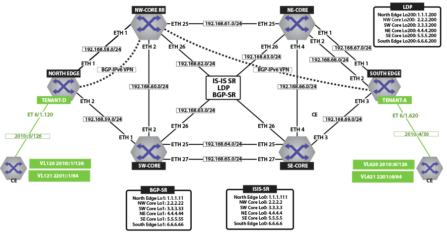
via 192.168.168.20, Ethernet6/3.2 evpn VXLAN IPv6 Overlay
Beginning with eos Release 4.22.0F, the evpn VXLAN L3 Gateway using evpn IRB supports routing traffic from one IPv6 host to another IPv6 host on a stretched VXLAN VLAN.
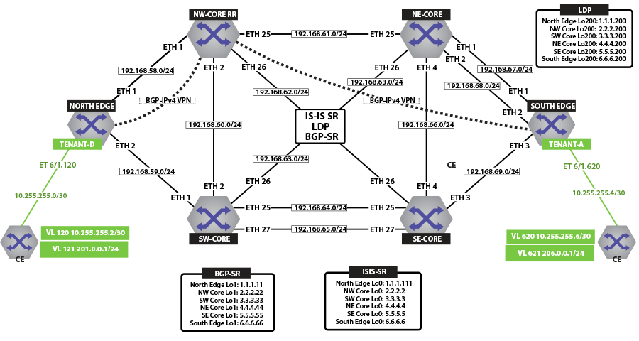
IP VPNs Sample Configuration
Here, we examine BGP evpn layer 3 VPN over an LDP, ISIS-SR, and BGP-SR transport LSPs. This highlights the separation between the transport and the VPN overlay service.
The following figures illustrate the sample VPN Physical Topology.
IP VPN over ISIS-SR
The following figure illustrates an overview of the combined control and data planes.

The next two figures illustrate the forwarding path and control plane for both IP traffic over ISIS MPLS segment routing.

View IPv4 and IPv6 Routes in the VRF
North Edge and South Edge routers have an eBGP peering session out to the CE; and learning routes from CE and remote PE.
-
The show ip route vrf tenant-d command displays IPv4 Routes in the VRF of North Edge.
north-edge# show ip route vrf tenant-d VRF: tenant-d Codes: C - connected, S - static, K - kernel, O - OSPF, IA - OSPF inter area, E1 - OSPF external type 1, E2 - OSPF external type 2, N1 - OSPF NSSA external type 1, N2 - OSPF NSSA external type2, B I - iBGP, B E - eBGP, R - RIP, I L1 - IS-IS level 1, I L2 - IS-IS level 2, O3 - OSPFv3, A B - BGP Aggregate, A O - OSPF Summary, NG - Nexthop Group Static Route, V - VXLAN Control Service, DH - DHCP client installed default route, M - Martian, DP - Dynamic Policy Route Gateway of last resort is not set B I 10.255.255.0/30 [200/0] via 6.6.6.6/32, IS-IS SR tunnel index 6, label 967920 via 192.168.58.12, Ethernet1/1, label 408006 C 10.255.255.4/30 is directly connected, Ethernet6/1.120 B E 201.0.0.0/24 [200/0] via 10.255.255.6, Ethernet6/1.120 B I 206.0.0.0/24 [200/0] via 6.6.6.6/32, IS-IS SR tunnel index 6, label 967920 via 192.168.58.12, Ethernet1/1, label 408006 -
The show ip route vrf tenant-d command displays IPv4 Routes in the VRF of South Edge.
south-edge# show ip route vrf tenant-d VRF: tenant-d Codes: C - connected, S - static, K - kernel, O - OSPF, IA - OSPF inter area, E1 - OSPF external type 1, E2 - OSPF external type 2, N1 - OSPF NSSA external type 1, N2 - OSPF NSSA external type2, B I - iBGP, B E - eBGP, R - RIP, I L1 - IS-IS level 1, I L2 - IS-IS level 2, O3 - OSPFv3, A B - BGP Aggregate, A O - OSPF Summary, NG - Nexthop Group Static Route, V - VXLAN Control Service, DH - DHCP client installed default route, M - Martian, DP - Dynamic Policy Route Gateway of last resort is not set C 10.255.255.0/30 is directly connected, Ethernet6/1.620 B I 10.255.255.4/30 [200/0] via 1.1.1.111/32, IS-IS SR tunnel index 5, label 951536 via 192.168.68.11, Ethernet2/1, label 408001 B I 201.0.0.0/24 [200/0] via 1.1.1.111/32, IS-IS SR tunnel index 5, label 951536 via 192.168.68.11, Ethernet2/1, label 408001 B E 206.0.0.0/24 [200/0] via 10.255.255.2, Ethernet6/1.620 -
The show ipv6 route vrf tenant-d command displays IPv6 Routes in the VRF of North Edge.
north-edge# show ipv6 route vrf tenant-d VRF: tenant-d Displaying 4 of 7 IPv6 routing table entries Codes: C - connected, S - static, K - kernel, O3 - OSPFv3, B - BGP, R - RIP, A B - BGP Aggregate, I L1 - IS-IS level 1, I L2 - IS-IS level 2, DH - DHCP, NG - Nexthop Group Static Route, M - Martian, DP - Dynamic Policy Route B 2010::/126 [200/0] via 6.6.6.6/32, IS-IS SR tunnel index 6, label 965242 via 192.168.58.12, Ethernet1/1, label 408006 C 2010::4/126 [0/0] via Ethernet6/1.120, directly connected B 2201::/64 [200/0] via 2010::6, Ethernet6/1.120 B 2206::/64 [200/0] via 6.6.6.6/32, IS-IS SR tunnel index 6, label 965242 via 192.168.58.12, Ethernet1/1, label 408006 -
The show ipv6 route vrf tenant-d command displays IPv6 Routes in the VRF of South Edge.
south-edge# show ipv6 route vrf tenant-d

VRF: tenant-d
Displaying 4 of 7 IPv6 routing table entries
Codes: C - connected, S - static, K - kernel, O3 - OSPFv3, B - BGP, R - RIP, A B - BGP Aggregate, I L1 -
IS-IS level 1, I L2 - IS-IS level 2, DH - DHCP, NG - Nexthop Group Static Route, M - Martian, DP - Dynamic
Policy Route

 C    2010::/126 [0/0]
       via Ethernet6/1.620, directly connected
 B    2010::4/126 [200/0]
       via 1.1.1.111/32, IS-IS SR tunnel index 5, label 948858
          via 192.168.68.11, Ethernet2/1, label 408001
 B    2201::/64 [200/0]
       via 1.1.1.111/32, IS-IS SR tunnel index 5, label 948858
          via 192.168.68.11, Ethernet2/1, label 408001
 B    2206::/64 [200/0]
       via 2010::2, Ethernet6/1.620
Activating IP VPN
In all scenarios, the IP VPN must be activated under BGP and neighbors configured to exchange the IP VPN NLRIs.The tenant’s VRF (tenant-d) is associated with a dynamically assigned label by BGP.
North Edge
service routing protocols model multi-agent

router bgp 64512
   router-id 1.1.1.111
   maximum-paths 128 ecmp 128
   neighbor 2.2.2.222 remote-as 64512
   neighbor 2.2.2.222 update-source Loopback0
   neighbor 2.2.2.222 bfd
   neighbor 2.2.2.222 send-community extended
   neighbor 2.2.2.222 maximum-routes 12000
   !
   address-family vpn-ipv4
      neighbor 2.2.2.222 activate
      neighbor default encapsulation mpls next-hop-self source-interface Loopback0
   !
   address-family vpn-ipv6
      neighbor 2.2.2.222 activate
      neighbor default encapsulation mpls next-hop-self source-interface Loopback0
   !
South Edge
service routing protocols model multi-agent

router bgp 64512
   router-id 6.6.6.6
   maximum-paths 128 ecmp 128
   neighbor 2.2.2.222 remote-as 64512
   neighbor 2.2.2.222 update-source Loopback0
   neighbor 2.2.2.222 bfd
   neighbor 2.2.2.222 send-community extended
   neighbor 2.2.2.222 maximum-routes 12000
   !
   address-family vpn-ipv4
      neighbor 2.2.2.222 activate
      neighbor default encapsulation mpls next-hop-self source-interface Loopback0
   !
   address-family vpn-ipv6
      neighbor 2.2.2.222 activate
      neighbor default encapsulation mpls next-hop-self source-interface Loopback0
   !
The configuration above provides the following:
- It enables the multi-agent routing protocol model, which is required for BGP VPN support.
- It sets the local autonomous system number to 64512 and configured the route-reflector for both IPv4 VPN and IPv6 VPN capabilities.
- It sets the IP VPN encapsulation type to MPLS (default).
- It specifies that Loopback0 will be used as the next-hop for all advertised VPN routes. The underlay configuration must provide MPLS LSPs from remote PEs to this loopback interface address.
Layer 3 Overlay Configuration
Distribution of Layer 3 routes over BGP is enabled by configuring one or more IP VRFs under the router bgp configuration mode. Additionally, either IPv4 or IPv6 routing must be enabled in the VRF.
-
Configure IP VRF in the North Edge router.
vrf instance tenant-d ip routing vrf tenant-d ipv6 unicast-routing vrf tenant-d ! router bgp 64512 vrf tenant-d rd 1.1.1.1:64514 route-target import vpn-ipv4 64512:4364 route-target import vpn-ipv6 64512:4364 route-target export vpn-ipv4 64512:4364 route-target export vpn-ipv6 64512:4364 neighbor 10.255.255.6 remote-as 65011 neighbor 10.255.255.6 maximum-routes 12000 neighbor 2010::6 remote-as 65011 neighbor 2010::6 maximum-routes 12000 ! address-family ipv6 neighbor 2010::6 activate redistribute connected ! -
Configure IP VRF in the South Edge router.
vrf instance tenant-d
ip routing vrf tenant-d
ipv6 unicast-routing vrf tenant-d
!
router bgp 64512
   vrf tenant-d
      rd 6.6.6.6:64514
      route-target import vpn-ipv4 64512:4364
      route-target import vpn-ipv6 64512:4364
      route-target export vpn-ipv4 64512:4364
      route-target export vpn-ipv6 64512:4364
      neighbor 10.255.255.2 remote-as 65010
      neighbor 10.255.255.2 maximum-routes 12000
      neighbor 2010::2 remote-as 65010
      neighbor 2010::2 maximum-routes 12000
      !
      address-family ipv6
         neighbor 2010::2 activate
       redistribute connected
      !
- It defines overlay VRFs (tenant-d) on the PE and enables IP unicast routing.
- The VRF is assigned a unique Route-Distinguisher (RD). The RD allows the PE to advertise VPN routes for the same IP prefix that have been exported by different VRFs. The NLRI RouteKey of a route exported from the VRFs IPv4 table into VPN consists of both the RD and the original IP prefix.
- The Route-Target (RT) extended communities for the VRF. The RTs are associated with all routes exported from the VRF. Received VPN routes carrying at least one RT matching the VRFs configuration are imported into the VRF.
Verifying IP VPNs over ISIS-SR
-
The show bgp vpn-ipv4 summary command displays the status of the VPN IP peers in the North Edge router with the BGP VPN enabled.
north-edge# show bgp vpn-ipv4 summary BGP summary information for VRF default Router identifier 1.1.1.111, local AS number 64512 Neighbor Status Codes: m - Under maintenance Neighbor V AS MsgRcvd MsgSent InQ OutQ Up/Down State PfxRcd PfxAcc 2.2.2.222 4 64512 172 45 0 0 00:17:16 Estab 2 2 north-edge# show bgp vpn-ipv6 summary BGP summary information for VRF default Router identifier 1.1.1.111, local AS number 64512 Neighbor Status Codes: m - Under maintenance Neighbor V AS MsgRcvd MsgSent InQ OutQ Up/Down State PfxRcd PfxAcc 2.2.2.222 4 64512 172 45 0 0 00:17:20 Estab 2 2 -
The show bgp vpn-ipv4 command displays routes sent and received through IP VPN.
north-edge# show bgp vpn-ipv4
BGP routing table information for VRF default
Router identifier 1.1.1.111, local AS number 64512
Route status codes: s - suppressed, * - valid, > - active, # - not installed, E - ECMP head, e - ECMP
                    S - Stale, c - Contributing to ECMP, b - backup
                    % - Pending BGP convergence
Origin codes: i - IGP, e - EGP, ? - incomplete
AS Path Attributes: Or-ID - Originator ID, C-LST - Cluster List, LL Nexthop - Link Local Nexthop

         Network             Next Hop         Metric  LocPref Weight Path
 * >     RD: 6.6.6.6:64514 IPv4 prefix 10.255.255.0/30
                             6.6.6.6          -       100     0      65010 i Or-ID: 6.6.6.6 C-LST: 2.2.2.222
 * >     RD: 1.1.1.1:64514 IPv4 prefix 10.255.255.4/30
                             -                -       100     0      65011 i
 * >     RD: 1.1.1.1:64514 IPv4 prefix 201.0.0.0/24
                             -                -       100     0      65011 i
 * >     RD: 6.6.6.6:64514 IPv4 prefix 206.0.0.0/24
                             6.6.6.6          -       100     0      65010 i Or-ID: 6.6.6.6 C-LST: 2.2.2.222

north-edge# show bgp vpn-ipv6
BGP routing table information for VRF default
Router identifier 1.1.1.111, local AS number 64512
Route status codes: s - suppressed, * - valid, > - active, # - not installed, E - ECMP head, e - ECMP
                    S - Stale, c - Contributing to ECMP, b - backup
                    % - Pending BGP convergence
Origin codes: i - IGP, e - EGP, ? - incomplete
AS Path Attributes: Or-ID - Originator ID, C-LST - Cluster List, LL Nexthop - Link Local Nexthop

         Network             Next Hop         Metric  LocPref Weight Path
 * >     RD: 6.6.6.6:64514 IPv6 prefix 2010::/126
                             6.6.6.6          -       100     0      65010 i Or-ID: 6.6.6.6 C-LST: 2.2.2.222
 * >     RD: 1.1.1.1:64514 IPv6 prefix 2010::4/126
                             -                -       100     0      65011 i
 * >     RD: 1.1.1.1:64514 IPv6 prefix 2201::/64
                             -                -       100     0      65011 i
 * >     RD: 6.6.6.6:64514 IPv6 prefix 2206::/64
                             6.6.6.6          -       100     0      65010 i Or-ID: 6.6.6.6 C-LST: 2.2.2.222
Note: Each entry in the table represents a BGP path. The path specific information includes the Route-Distinguisher and the IP prefix. Paths are either received from VPN peers or exported from local VRFs. -
The show bgp vpn-ipv4 206.0.0.0/24 detail and show bgp vpn-ipv6 2206::/64 detail commands display detailed view of the IP prefix route for 206.0.0.0/24 and 2206.::/64 of the North Edge router.
north-edge# show bgp vpn-ipv4 206.0.0.0/24 detail
BGP routing table information for VRF default
Router identifier 1.1.1.111, local AS number 64512
BGP routing table entry for IPv4 prefix 206.0.0.0/24, Route Distinguisher: 6.6.6.6:64514
 Paths: 1 available
  65010
    6.6.6.6 from 2.2.2.222 (2.2.2.222)
      Origin IGP, metric -, localpref 100, weight 0, valid, internal, best
      Extended Community: Route-Target-AS:64512:4364
      MPLS label: 967920

north-edge# show bgp vpn-ipv6 2206::/64 detail
BGP routing table information for VRF default
Router identifier 1.1.1.111, local AS number 64512
BGP routing table entry for IPv6 prefix 2206::/64, Route Distinguisher: 6.6.6.6:64514
 Paths: 1 available
  65010
    6.6.6.6 from 2.2.2.222 (2.2.2.222)
      Origin IGP, metric -, localpref 100, weight 0, valid, internal, best
      Extended Community: Route-Target-AS:64512:4364
      MPLS label: 965242
Note: The output includes the RD and IP prefixes identifying the route. As seen in the output, the IPv4 VPN route is received from 2.2.2.222 because it is set-up to be a route-reflector, but the next hop is 6.6.6.6. Both are advertised with tenant VPN label 967920 and 965242 and an RT. -
The show ip bgp vrf tenant-d command displays the BGP table for the VRF containing the imported evpn routes.
north-edge# show ip bgp vrf tenant-d
BGP routing table information for VRF tenant-d
Router identifier 1.1.1.1, local AS number 64512
Route status codes: s - suppressed, * - valid, > - active, # - not installed, E - ECMP head, e - ECMP
                    S - Stale, c - Contributing to ECMP, b - backup, L - labeled-unicast
                    % - Pending BGP convergence
Origin codes: i - IGP, e - EGP, ? - incomplete
AS Path Attributes: Or-ID - Originator ID, C-LST - Cluster List, LL Nexthop - Link Local Nexthop
         Network             Next Hop         Metric  LocPref Weight Path
 * >Ec   10.255.255.0/30     6.6.6.6          -       100     0      65010 i Or-ID: 6.6.6.6 C-LST: 2.2.2.222
 *  ec   10.255.255.0/30     6.6.6.6          -       100     0      65010 i Or-ID: 6.6.6.6 C-LST: 2.2.2.222
 * >     10.255.255.4/30     10.255.255.6     -       100     0      65011 i
 * >     201.0.0.0/24        10.255.255.6     -       100     0      65011 i
 * >Ec   206.0.0.0/24        6.6.6.6          -       100     0      65010 i Or-ID: 6.6.6.6 C-LST: 2.2.2.222
 *  ec   206.0.0.0/24        6.6.6.6          -       100     0      65010 i Or-ID: 6.6.6.6 C-LST: 2.2.2.222
Note: Each entry in the table represent a BGP path that is either locally redistributed and received into the VRF or imported from the IPv4 VPN table. VPN routes are received from router 2.2.2.222 C-List (cluster list - basically identifying this route as from a route-reflector) with originating router being 6.6.6.6.
Finally, let us look at the routes in the VRF tenant-d.
VRF: tenant-d
Codes: C - connected, S - static, K - kernel,
       O - OSPF, IA - OSPF inter area, E1 - OSPF external type 1,
       E2 - OSPF external type 2, N1 - OSPF NSSA external type 1,
       N2 - OSPF NSSA external type2, B I - iBGP, B E - eBGP,
       R - RIP, I L1 - IS-IS level 1, I L2 - IS-IS level 2,
       O3 - OSPFv3, A B - BGP Aggregate, A O - OSPF Summary,
       NG - Nexthop Group Static Route, V - VXLAN Control Service,
       DH - DHCP client installed default route, M - Martian,
       DP - Dynamic Policy Route

Gateway of last resort is not set

 B I    10.255.255.0/30 [200/0] via 6.6.6.6/32, IS-IS SR tunnel index 6, label 967920
                                   via 192.168.58.12, Ethernet1/1, label 408006
 C      10.255.255.4/30 is directly connected, Ethernet6/1.120
 B E    201.0.0.0/24 [200/0] via 10.255.255.6, Ethernet6/1.120
 B I    206.0.0.0/24 [200/0] via 6.6.6.6/32, IS-IS SR tunnel index 6, label 967920
via 192.168.58.12, Ethernet1/1, label 408006A check of the Tunnel FIB confirms that 408006 is the ISIS-SR LSP.
north-edge# show mpls tunnel fib
! 'show mpls tunnel fib' has been deprecated. Please use 'show tunnel fib [options]' moving forward.
   Tunnel Type         Index       Endpoint           Nexthop             Interface          Labels        Forwarding
------------------- --------- ------------------ ------------------- ------------------ ----------------
   IS-IS SR IPv4       9           2.2.2.22/32        192.168.58.12       Ethernet1/1        [ 3 ]         None
   LDP                 4           2.2.2.200/32       192.168.58.12       Ethernet1/1        [ 3 ]         None
   IS-IS SR IPv4       2           2.2.2.222/32       192.168.58.12       Ethernet1/1        [ 3 ]         None
   IS-IS SR IPv4       4           3.3.3.3/32         192.168.58.12       Ethernet1/1        [ 408003 ]    None
   BGP LU              5           3.3.3.33/32        192.168.58.12       Ethernet1/1        [ 200033 ]    None
   LDP                 5           3.3.3.200/32       192.168.58.12       Ethernet1/1        [ 904099 ]    None
   IS-IS SR IPv4       8           4.4.4.4/32         192.168.58.12       Ethernet1/1        [ 408004 ]    None
   IS-IS SR IPv4       5           4.4.4.44/32        192.168.58.12       Ethernet1/1        [ 408044 ]    None
   LDP                 2           4.4.4.200/32       192.168.58.12       Ethernet1/1        [ 904098 ]    None
   IS-IS SR IPv4       3           5.5.5.5/32         192.168.58.12       Ethernet1/1        [ 408005 ]    Primary
   BGP LU              7           5.5.5.55/32        192.168.58.12       Ethernet1/1        [ 200055 ]    None
   LDP                 3           5.5.5.200/32       192.168.58.12       Ethernet1/1        [ 904100 ]    None
   IS-IS SR IPv4       6           6.6.6.6/32         192.168.58.12       Ethernet1/1        [ 408006 ]    Primary
   BGP LU              8           6.6.6.66/32        192.168.58.12       Ethernet1/1        [ 200066 ]    None
   LDP                 1           6.6.6.200/32       192.168.58.12       Ethernet1/1        [ 904097 ]    None
   IS-IS SR IPv4       1           23.1.1.11/32       192.168.1.154       Ethernet36/1       [ 3 ]         Primary
   IS-IS SR IPv4       7           23.1.1.33/32       192.168.1.174       Ethernet23/1       [ 3 ]         Primary
IP VPNs Over LDP
The following figures illustrate an overview of the combined control and data planes.
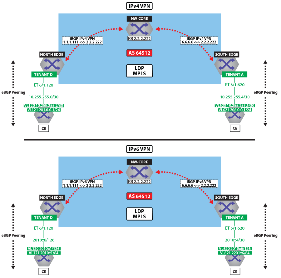
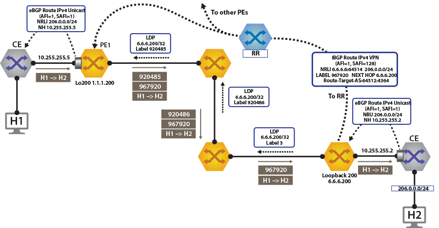

To switch to using the MPLS LDP transport, we just need to change the next-hop we advertised for the VPN routes. As shown, the next hop needs to be set to loopback 200 for using the LDP LSP.
This is achieved by configuring the next-hop for the evpn routes on both north and south edge routers.
router bgp 64512
   !
   address-family evpn
     neighbor default encapsulation mpls next-hop-self source-interface Loopback200
After this is configured, check the BGP updates and the routes in the VRF. The output again includes the RD and IP prefix identifying the route. Now the NH is set to 6.6.6.200 for tenant-d.
north-edge# show bgp vpn-ipv4 206.0.0.0/24 detail
BGP routing table information for VRF default
Router identifier 1.1.1.111, local AS number 64512
BGP routing table entry for IPv4 prefix 206.0.0.0/24, Route Distinguisher: 6.6.6.6:64514
 Paths: 1 available
  65010
    6.6.6.200 from 2.2.2.222 (2.2.2.222)
      Origin IGP, metric -, localpref 100, weight 0, valid, internal, best
      Extended Community: Route-Target-AS:64512:4364
      MPLS label: 967920
north-edge#

north-edge# show bgp vpn-ipv6 2206::/64 detail
BGP routing table information for VRF default
Router identifier 1.1.1.111, local AS number 64512
BGP routing table entry for IPv6 prefix 2206::/64, Route Distinguisher: 6.6.6.6:64514
 Paths: 1 available
  65010
    6.6.6.200 from 2.2.2.222 (2.2.2.222)
      Origin IGP, metric -, localpref 100, weight 0, valid, internal, best
      Extended Community: Route-Target-AS:64512:4364
      MPLS label: 965242
north-edge#north-edge# show ip route vrf tenant-d
VRF: tenant-d
Codes: C - connected, S - static, K - kernel,
O - OSPF, IA - OSPF inter area, E1 - OSPF external type 1,
E2 - OSPF external type 2, N1 - OSPF NSSA external type 1,
N2 - OSPF NSSA external type2, B I - iBGP, B E - eBGP,
R - RIP, I L1 - IS-IS level 1, I L2 - IS-IS level 2,
O3 - OSPFv3, A B - BGP Aggregate, A O - OSPF Summary,
NG - Nexthop Group Static Route, V - VXLAN Control Service,
DH - DHCP client installed default route, M - Martian,
DP - Dynamic Policy Route
Gateway of last resort is not set
B I 10.255.255.0/30 [200/0] via 6.6.6.200/32, LDP tunnel index 1, label 967920
via 192.168.58.12, Ethernet1/1, label 904097
C 10.255.255.4/30 is directly connected, Ethernet6/1.120
B E 201.0.0.0/24 [200/0] via 10.255.255.6, Ethernet6/1.120
B I 206.0.0.0/24 [200/0] via 6.6.6.200/32, LDP tunnel index 1, label 967920
via 192.168.58.12, Ethernet1/1, label 904097
north-edge(config-router-bgp)# show ipv6 route vrf tenant-d
VRF: tenant-d
Displaying 4 of 7 IPv6 routing table entries
Codes: C - connected, S - static, K - kernel, O3 - OSPFv3, B - BGP, R - RIP, A B - BGP Aggregate,
I L1 - IS-IS level 1, I L2 - IS-IS level 2, DH - DHCP, NG - Nexthop Group Static Route,
M - Martian, DP - Dynamic Policy Route
B 2010::/126 [200/0]
via 6.6.6.6/32, IS-IS SR tunnel index 6, label 965242
via 192.168.58.12, Ethernet1/1, label 408006
C 2010::4/126 [0/0]
via Ethernet6/1.120, directly connected
B 2201::/64 [200/0]
via 2010::6, Ethernet6/1.120
B 2206::/64 [200/0]
via 6.6.6.6/32, IS-IS SR tunnel index 6, label 965242
via 192.168.58.12, Ethernet1/1, label 408006A capture of the dataplane on North-Edge matching on the LDP transport label confirms the encapsulated traffic on the wire. 904097:976920:[Source IP Address][Destination IP Address].
IP VPNs Over BGP-SR
The following figures illustrate an overview of the combined control and data planes.
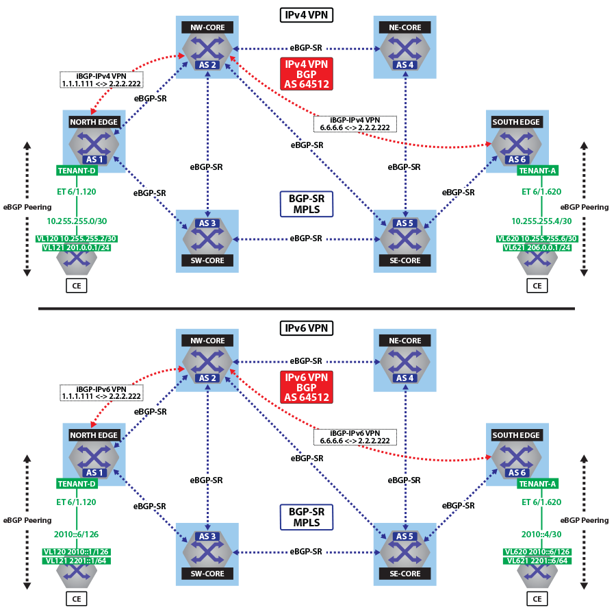
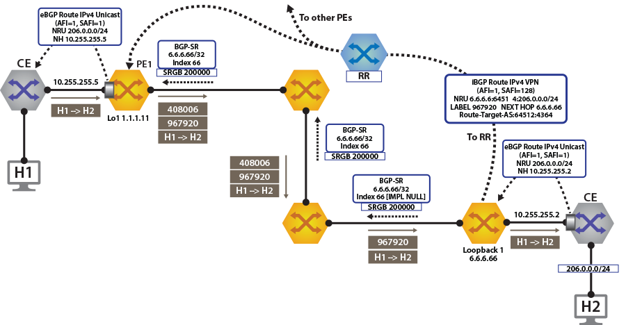

To switch to using the MPLS BGP-SR transport, we just need to change the next-hop we advertised for the VPN routes. As shown, the next hop needs to be set to loopback 1 for using the BGP-SR LSP.
This is achieved by configuring the next-hop for evpn routes.
router bgp 64512
   !
   address-family evpn
     neighbor default encapsulation mpls next-hop-self source-interface Loopback1
Once this is configured, we can check the BGP updates and the routes in the VRF. The output again includes the RD and IP prefix identifying the route. As seen in the output, we now have the NH set to 6.6.6.66 for tenant-d.
north-edge# show bgp vpn-ipv4 206.0.0.0/24 detail
BGP routing table information for VRF default
Router identifier 1.1.1.111, local AS number 64512
BGP routing table entry for IPv4 prefix 206.0.0.0/24, Route Distinguisher: 6.6.6.6:64514
 Paths: 1 available
  65010
    6.6.6.66 from 2.2.2.222 (2.2.2.222)
      Origin IGP, metric -, localpref 100, weight 0, valid, internal, best
      Extended Community: Route-Target-AS:64512:4364
      MPLS label: 967920
north-edge#
north-edge#show bgp vpn-ipv6 2206::/64 detail
BGP routing table information for VRF default
Router identifier 1.1.1.111, local AS number 64512
BGP routing table entry for IPv6 prefix 2206::/64, Route Distinguisher: 6.6.6.6:64514
 Paths: 1 available
  65010
    6.6.6.66 from 2.2.2.222 (2.2.2.222)
      Origin IGP, metric -, localpref 100, weight 0, valid, internal, best
      Extended Community: Route-Target-AS:64512:4364
      MPLS label: 965242
north-edge#The output again includes the RD and IP prefix identifying the route. As seen in the output, we now have the NH set to 6.6.6.66 for tenant-d.
north-edge# show bgp vpn-ipv4 206.0.0.0/24 detail
BGP routing table information for VRF default
Router identifier 1.1.1.111, local AS number 64512
BGP routing table entry for IPv4 prefix 206.0.0.0/24, Route Distinguisher: 6.6.6.6:64514
 Paths: 1 available
  65010
    6.6.6.66 from 2.2.2.222 (2.2.2.222)
      Origin IGP, metric -, localpref 100, weight 0, valid, internal, best
      Extended Community: Route-Target-AS:64512:4364
      MPLS label: 967920
north-edge#
north-edge# show bgp vpn-ipv6 2206::/64 detail
BGP routing table information for VRF default
Router identifier 1.1.1.111, local AS number 64512
BGP routing table entry for IPv6 prefix 2206::/64, Route Distinguisher: 6.6.6.6:64514
 Paths: 1 available
  65010
    6.6.6.66 from 2.2.2.222 (2.2.2.222)
      Origin IGP, metric -, localpref 100, weight 0, valid, internal, best
      Extended Community: Route-Target-AS:64512:4364
      MPLS label: 965242
north-edge#As displayed in the highlighted route above the label stack, the route are the transport label 200066 on top (this is the label path to reach NH 6.6.6.66), with the tenant-d VPN label 967920 next in the stack, and identifying the route as belonging to tenant-a.
north-edge# show ip route vrf tenant-d

VRF: tenant-d
Codes: C - connected, S - static, K - kernel,
       O - OSPF, IA - OSPF inter area, E1 - OSPF external type 1,
       E2 - OSPF external type 2, N1 - OSPF NSSA external type 1,
       N2 - OSPF NSSA external type2, B I - iBGP, B E - eBGP,
       R - RIP, I L1 - IS-IS level 1, I L2 - IS-IS level 2,
       O3 - OSPFv3, A B - BGP Aggregate, A O - OSPF Summary,
       NG - Nexthop Group Static Route, V - VXLAN Control Service,
       DH - DHCP client installed default route, M - Martian,
       DP - Dynamic Policy Route

Gateway of last resort is not set

 B I    10.255.255.0/30 [200/0] via 6.6.6.66/32, BGP LU tunnel index 8, label 967920
                                   via 192.168.58.12, Ethernet1/1, label 200066
                                   via 192.168.59.12, Ethernet2/1, label 200066
 C      10.255.255.4/30 is directly connected, Ethernet6/1.120
 B E    201.0.0.0/24 [200/0] via 10.255.255.6, Ethernet6/1.120
 B I    206.0.0.0/24 [200/0] via 6.6.6.66/32, BGP LU tunnel index 8, label 967920
                                via 192.168.58.12, Ethernet1/1, label 200066
                                via 192.168.59.12, Ethernet2/1, label 200066

north-edge(config-router-bgp)# show ipv6 route vrf tenant-d

VRF: tenant-d
Displaying 4 of 7 IPv6 routing table entries
Codes: C - connected, S - static, K - kernel, O3 - OSPFv3, B - BGP, R - RIP, A B - BGP Aggregate, I L1 -
IS-IS level 1, I L2 - IS-IS level 2, DH - DHCP, NG - Nexthop Group Static Route, M - Martian, DP - Dynamic
Policy Route

 B    2010::/126 [200/0]
       via 6.6.6.66/32, BGP LU tunnel index 8, label 965242
          via 192.168.58.12, Ethernet1/1, label 200066
          via 192.168.59.12, Ethernet2/1, label 200066
 C    2010::4/126 [0/0]
       via Ethernet6/1.120, directly connected
 B    2201::/64 [200/0]
       via 2010::6, Ethernet6/1.120
 B    2206::/64 [200/0]
       via 6.6.6.66/32, BGP LU tunnel index 8, label 965242
          via 192.168.58.12, Ethernet1/1, label 200066
          via 192.168.59.12, Ethernet2/1, label 200066
A capture of the data-plane on North-Edge matching on the BGP-SR transport label confirms the encapsulated traffic on the wire. 200066:976920:[Source IP Address][Destination IP Address].
monitor session 1 source Ethernet1/1 tx
monitor session 1 destination Cpu

north-edge(config-router-bgp)# bash tcpdump -nei mirror0 -q -c 10 mpls 200066
tcpdump: verbose output suppressed, use -v or -vv for full protocol decode
listening on mirror0, link-type EN10MB (Ethernet), capture size 262144 bytes
16:37:15.074916 28:99:3a:4d:3e:f1 > 28:99:3a:4d:3a:f3, MPLS unicast, length 122: MPLS (label 200066, exp 0,
ttl 63) (label 967920, exp 0, [S], ttl 63) 10.255.255.6 > 206.0.0.1: ICMP echo request, id 22573, seq 1,
length 80

16:37:15.075088 28:99:3a:4d:3e:f1 > 28:99:3a:4d:3a:f3, MPLS unicast, length 122: MPLS (label 200066, exp 0,
ttl 63) (label 967920, exp 0, [S], ttl 63) 10.255.255.6 > 206.0.0.1: ICMP echo request, id 22573, seq 2, length 80