Open Shortest Path First – Version 2
Open Shortest Path First (OSPF) is a link-state routing protocol that operates within a single autonomous system. OSPF version 2 is defined by RFC 2328.
OSPFv2 Introduction
Supported Features
- Multiple OSPFv2 instances on a VRF.
- Intra- and inter-area routing.
- Type 1 and 2 external routing.
- Broadcast and P2P interfaces.
- Stub areas.
- Not so stubby areas (NSSA) (RFC 3101).
- MD5 Authentication.
- Redistribution of static, IP, and BGP routes into OSPFv2 with route map filtering.
- Opaque LSAs (RFC 2370).
- Graceful restart (RFC 3623).
- OSPF Routes over GRE Tunnels.
Features Not Supported
- NBMA, demand circuit, and P2MP interfaces.
- OSPFv2 MIB support.
OSPFv2 Conceptual Overview
Storing Link States
OSPFv2 is a dynamic, link-state routing protocol where links represent interfaces or routable paths. Dynamic routing protocols calculate the most efficient path between locations based on bandwidth and device status.
A Link State Advertisement (LSA) is an OSPFv2 packet that communicates a router's topology to other routers. The Link State Database (LSDB) stores an area's topology database and comprises LSAs received from other routers. Routers update the LSDB by storing LSAs from other routers.
Topology
An Autonomous System (AS) is the IP domain where a dynamic protocol controls traffic routing. In OSPFv2, an AS comprises areas that define the LSDB computation boundaries—all routers in an area store identical LSDBs. Routers in different areas exchange updates without storing the entire database, reducing information maintenance on large, dynamic networks.
An AS shares internal routing information from its areas and external routing information from other processes to inform routers outside the AS about routes the network can access. Routers that advertise routes on other ASs commit to carrying data to the IP space on the route.
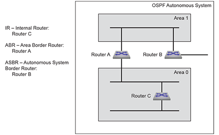
- An Internal Router (IR) is a router whose interfaces are contained in a single area. All IRs in an area maintain identical LSDBs.
- An Area Border Router (ABR) is a router that has interfaces in multiple areas and maintains one LSDB for each connected area.
- An Autonomous System Boundary Router (ASBR) is a gateway router connecting the OSPFv2 domain to external routes, including static routes and routes from other autonomous systems.
- OSPFv2 Router Types displays the OSPFv2 router types.
OSPFv2 areas are assigned a number between 0 and 4,294,967,295 (2321). Area numbers are often expressed in dotted decimal notation, similar to IP addresses.
Each AS has a backbone area, designated as area 0, that connects to all other areas. The backbone receives routing information from all areas, then distributes it to the other areas as required.
- Normal area accepts intra-area, inter-area, and external routes. The backbone is a normal area.
- Stub area does not receive router advertisements external to the AS. Stub area routing is based on a default route.
- Not-So-Stubby-Area (NSSA) may import external routes from an ASBR, does not receive external routes from the backbone, and does not propagate external routes to other areas.
Link Updates
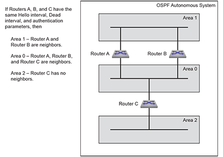
- share a common network segment.
- are in the same area.
- have the same hello interval, dead interval, and authentication parameters.
Neighbors form adjacencies to exchange LSDB information. A neighbor group uses hello packets to elect a Designated Router (DR) and Backup Designated Router (BDR). The DR and BDR become adjacent to all other neighbors, including each other. Only adjacent neighbors share database information.
OSPFv2 Neighbors illustrates OSPFv2 neighbors.
The DR is the central contact for database exchanges. Switches send database information to their DR, which relays the information to the other neighbors. All routers in an area maintain identical LSDBs. Switches also send database information to their BDR, which stores this data without distributing it. If the DR fails, the BDR distributes LSDB information to its neighbors.
OSPFv2 routers distribute LSAs by sending them on all of their active interfaces. The router generates an LSA for a network defined and active on a passive interface but will not transmit this LSA on the passive interface as no adjacencies are formed.
When an LSA changes a router's LSDBA, it sends the changes to the DR and BDR for distribution to the other neighbors. Routing information is updated only when the topology changes.
Routers use the Dijkstra algorithm to calculate the shortest path to all known destinations, based on cumulative route cost. The cost of an interface indicates the transmission overhead and is usually inversely proportional to its bandwidth.
OSPFv2 Route Redistribution Instance
OSPFv2 Route Redistribution is used for redistributing OSPFv2 leaked and non-leaked routes from one instance to another when multiple OSPFv2 instances are configured. The OSPFv2 Route Redistribution is supported on all platforms in the multi-agent routing mode.
OSPFv2 and BFD Sessions for Adjacencies in any State
BFD sessions are only established for OSPFv2 adjacencies that are in the FULL state. In a LAN environment this results in BFD sessions not being established for OSPFv2 adjacencies with DR Other neighbors.
This feature provides a configuration that enables the establishment of BFD sessions for OSPFv2 adjacencies that are in any state. This results in the BFD sessions being established for OSPFv2 adjacencies with DR Other neighbors.
OSPFv2 Multiple Instances Support
EOS supports multiple OSPFv2 instance configurations on the default VRF and provides isolation as well as segregation and division of the link state database based on the interface.
EOS also supports graceful restart and BFD with multiple OSPFv2 instances on switches.
OSPFv2 Multiple Instances Support Platform Compatibility
OSPFv2 Multiple Instances Support is supported on all platforms.
OSPF Routes over GRE Tunnels
This feature introduces support for OSPF routes over GRE tunnels under default and non-default VRFs. It is disabled by default.
Limitations
The platform does not support arbitrarily created TCAM profiles. When the TCAM profile cannot be programmed, the show command prints ERROR in the status column.
Configuring OSPFv2
- Configuring the OSPFv2 Instance
- Configuring OSPFv2 Areas
- Support for OSPFv2 dn-bit-ignore
- OSPFv2 Area Filter by Prefix-List
- IPv4 Unnumbered Interfaces
- Configuring Interfaces for OSPFv2
- Enabling OSPFv2
- OSPFv2 Multiple Instances Support Configuration
- OSPF Routes over GRE Tunnels Configuration
- Displaying OSPFv2 Status
Configuring the OSPFv2 Instance
Entering OSPFv2 Configuration Mode
The router ospf command places the switch in router-ospf configuration mode and creates an OSPFv2 instance if one was not previously created. The switch only supports one OSPFv2 instance and all OSPFv2 configuration commands apply to this instance.
When an OSPFv2 instance is already configured, the command must specify its process ID. Any attempt to define additional instances will fail and generate errors.
The process ID is local to the router and is used to identify the running OSPFv2 process. Neighbor OSPFv2 routers can have different process IDs.
Example
switch(config)# router ospf 100
switch(config-router-ospf)#
Defining the Router ID
The router ID is a 32-bit number assigned to a router running OSPFv2. This number uniquely labels the router within an Autonomous System. Status commands identify the switch through the router ID.
- The router-id command.
- The loopback IP address, if an active loopback interface exists on the switch.
- The highest IP address on the router.Note: When configuring VXLAN on an MLAG, always manually configure the OSPFv2 router ID to prevent the switch from using the common VTEP IP address as the router ID.
The router-id (OSPFv2) command configures the router ID for an OSPFv2 instance.
Example
switch(config-router-ospf)# router-id 10.1.1.1
switch(config-router-ospf)#
Global OSPFv2 Parameters
These router-ospf configuration mode commands define OSPFv2 behavior.
LSA Overload
- Warning: the switch logs OSPF MAXLSAWARNING if the LSDB contains a specified percentage of the LSA maximum.
- Temporary shutdown: when the LSDB exceeds the LSA maximum, OSPFv2 is disabled and does not accept or acknowledge new LSAs. The switch restarts OSPFv2 after a specified period (the default is 5 minutes).
- Permanent shutdown: the switch permanently disables OSPFv2 after performing a specified number of temporary shutdowns (the default is 5). This state usually indicates the need to resolve a network condition that consistently generates excessive LSA packets.
OSPFv2 is re-enabled with a router ospf command.
The LSDB size restriction is removed by setting the LSA limit to zero.
- This command configures the OSPFv2 maximum LSA count to
20000 and triggers these actions:
- The switch logs an OSPF MAXLSAWARNING if the LSDB has 8000 LSAs (40% of 20000).
- The switch temporarily disables OSPFv2 for 10 minutes if the LSDB contains 20000 LSAs.
- The switch permanently disables OSPFv2 after four temporary OSPFv2 shutdowns.
- The shutdown counter resets if the LSDB contains less than 20,000
LSAs for 20
minutes.
switch(config-router-ospf)# max-lsa 20000 40 ignore-time 10 ignore-count 4 reset-time 20
switch(config-router-ospf)#
Logging Adjacency Changes
The log-adjacency-changes (OSPFv2 command configures the switch to log OSPFv2 link-state changes and transitions of OSPFv2 neighbors into the up or down state.
- This command configures the switch to log transitions of OSPFv2 neighbors
into the up or down
state.
switch(config-router-ospf)# log-adjacency-changes switch(config-router-ospf)# - This command configures the switch to log all OSPFv2 link-state
changes.
switch(config-router-ospf)# log-adjacency-changes detail
switch(config-router-ospf)#
OSPF RFC Compatibility
RFC 2328 and RFC 1583 specify different methods for calculating summary route metrics. The compatible (OSPFv2) command allows the selective disabling of compatibility with RFC 2328.
Example
switch(config)# router ospf 6
switch(config-router-ospf)# compatible rfc1583
switch(config-router-ospf)#
Administrative Distance
The distance ospf (OSPFv2) command configures the administrative distance for intra-area, inter-area, or external OSPF routes. The command must be entered multiple times to configure the administrative distance for multiple route types. Administrative distances compare dynamic routes configured by different protocols. The default administrative distance for all routes is 110.
Example
switch(config-router-ospf)# distance ospf intra-area 95
switch(config-router-ospf)#
Passive Interfaces
The passive-interface (OSPFv2) command prevents the transmission of hello packets on the specified interface. Passive interfaces drop all adjacencies and do not form new adjacencies. Passive interfaces send LSAs but do not receive them. The router does not send or process OSPFv2 packets received on passive interfaces. The router advertises the passive-interface in the router LSA.
The no passive-interface command re-enables OSPFv2 processing on the specified interface.
- This command configures vlan 2 as a passive
interface.
switch(config-router-ospf)# passive-interface vlan 2 switch(config-router-ospf)# - This command configures vlan 2 as an active
interface.
switch(config-router-ospf)# no passive-interface vlan 2
switch(config-router-ospf)#
Redistributing Connected Routes
Redistributing connected routes causes the OSPFv2 instance to advertise all connected routes on the switch as external OSPFv2 routes. Connected routes are routes that are established when IPv4 is enabled on an interface.
Example
switch(config-router-ospf)# redistribute connected
switch(config-router-ospf)#
Redistributing Static Routes
Redistributing static routes causes the OSPFv2 instance to advertise all static routes on the switch as external OSPFv2 routes. The switch does not support redistributing individual static routes.
- The redistribute
(OSPFv2)
static command converts the static routes to OSPFv2 external
routes.
switch(config-router-ospf)# redistribute static switch(config-router-ospf)# - The no
redistribute
(OSPFv2) command stops the advertising of the
static routes as OSPFv2 external
routes.
switch(config-router-ospf)# no redistribute static
switch(config-router-ospf)#
Filtering Routes with Distribute Lists
An OSPF distribute list uses a route map or prefix list to filter specific routes from incoming OSPF LSAs; this filtering occurs after SPF calculation. The filtered routes are not installed on the switch but are still included in LSAs sent by the switch. An OSPF router instance can have one distribute list configured.
If a prefix list is used, destination prefixes that do not match the prefix list will not be installed. If a route map is used, routes may be filtered based on address, next hop, or metric. OSPF external routes may also be filtered by metric type or tag.
The distribute-list in command specifies the filter to be used and applies it to the OSPF instance.
Example
switch(config)# router ospf 5
switch(config-router-ospf)# distribute-list prefix-list dist_list1 in
switch(config-router-ospf)#
Configuring OSPFv2 Route Redistribution
Use the redistribute ospf instance command to redistribute either the non-leaked routes or both leaked and non-leaked routes. This command is configured under the router-ospf mode.
- The leaked clause includes both internal and external
routes.
switch(config-router-ospf)# redistribute ospf instance include leaked <cr> Options: include Include leaked routes match Routes learned by the OSPF protocol route-map Specify which route map to use - The match clause allows matching on the different
OSPFv2 route
types.
switch(config-router-ospf)# redistribute ospf instance match external <cr> Options: external OSPF routes learned from external sources internal OSPF routes learned from internal sources nssa-external OSPF routes learned from external NSSA sources - The following command redistributes the OSPFv2 external routes from all other
OSPFv2 instances in the same VRF into the given
instance.
switch(config-router-ospf)# redistribute ospf instance match external - The following command redistributes the OSPFv2 internal leaked and non-leaked
routes from all other instances in all VRFs into the given
instance.
switch(config-router-ospf)# redistribute ospf instance include leaked match internal - Matching based on the OSPFv2 instance ID is supported in the
route-map.
switch(config)# route-map rm1 permit 10 switch(config-route-map-rm1)# match ospf instance 3 - The following command redistributes the OSPFv2 external routes from the OSPFv2
instance with ID 3 in the same VRF into the given
instance.
switch(config-router-ospf)# redistribute ospf instance match external route-map rm1
Show Commands
- The show ip ospf database external command is used to verify if the AS-External LSAs are created in the instance for the redistributed route and advertised into the OSPFv2 domain.
- The show route-map command displays the details of a configured route-map.
Configuring OSPFv2 Areas
OSPFv2 areas are configured through area commands. The switch must be in router-ospf configuration mode, as described in Entering OSPFv2 Configuration Mode, to run area commands.
Areas are assigned a 32-bit number expressed in decimal or dotted-decimal notation. When an OSPFv2 instance configuration contains multiple areas, the switch only configures areas associated with its interfaces.
Configuring the Area Type
- Normal area: Area that accepts intra-area, inter-area, and external routes. The backbone area (area 0) is a normal area.
- Stub area: Area that does not advertise external routes. External routes are reached through a default summary route (::/0). Networks with no external routes do not require stub areas.
- Not So Stubby Area (NSSA): ASBRs advertise external LSAs directly connected to the area. External routes from other areas are not advertised and are reached through a default summary route.
The default area type is normal.
- This command configures area 45 as a stub
area.
switch(config-router-ospf)# area 45 stub switch(config-router-ospf)# - This command configures area 10.92.148.17 as an
NSSA.
switch(config-router-ospf)# area 10.92.148.17 NSSA
switch(config-router-ospf)#
Blocking All Summary Routes from Flooding the NSSA
The area nssa no-summary (OSPFv2) command configures the router to not import type-3 summary LSAs into the Not-So-Stubby Area (NSSA). It injects a default summary route (0.0.0.0/0) into the NSSA to reach the inter-area prefixes.
Example
switch(config)# router ospf 6
switch(config-router-ospf)# area 1.1.1.1 nssa no-summary
switch(config-router-ospf)#
Assigning Network Segments to the Area
Assigning Routes to an Area
The network area (OSPFv2) command assigns the specified network segment to an OSPFv2 area. The network can be entered using CIDR notation or an address and wildcard mask.
The switch zeroes the host portion of the specified network address. For example, 1.2.3.4/24 converts to 1.2.3.0/24, and 1.2.3.4/16 converts to 1.2.0.0/16.
Example
switch(config-router-ospf)# network 10.1.10.0 0.0.0.255 area 0
switch(config-router-ospf)# network 10.1.10.0/24 area 0
In each case, running-config stores the command in CIDR (prefix) notation.
Summarizing Routes
By default, Area Border Routers (ABRs) create a summary LSA for each route in an area and advertise them to adjacent routers. The area range (OSPFv2) command aggregates routing information, allowing the ABR to advertise multiple routes with one LSA. The area range (OSPFv2) command can be used to suppress route advertisements.
- Two network
area commands assign subnets to an area. The area range
(OSPFv2) command summarizes the addresses the ABR
advertises in a single
LSA.
switch(config-router-ospf)# network 10.1.25.80 0.0.0.240 area 5 switch(config-router-ospf)# network 10.1.25.112 0.0.0.240 area 5 switch(config-router-ospf)# area 5 range 10.1.25.64 0.0.0.192 switch(config-router-ospf)# - The network
area command assigns a subnet to an area, followed
by an area range
(OSPFv2) command that suppresses the advertisement
of that
subnet.
switch(config-router-ospf)# network 10.12.31.0 0.0.0.255 area 5
switch(config-router-ospf)# area 5 range 10.12.31.0 0.0.0.255 not-advertise
switch(config-router-ospf)#
Configuring Area Parameters
These router-ospf configuration mode commands define OSPFv2 behavior in a specified area.
Default Summary Route Cost
The area default-cost (OSPFv2) command specifies the cost of the default summary route that ABRs send into a stub area or NSSA. Summary routes, also called inter-area routes, originate in areas different than their destination.
Example
switch(config-router-ospf)# area 23 default-cost 15
switch(config-router-ospf)#
Filtering Type 3 LSAs
The area filter (OSPFv2) command prevents an area from receiving Type 3 (Summary) LSAs from a specified subnet. ABRs send type 3 LSAs and contain information about one of its connected areas.
Example
switch(config-router-ospf)# area 2 filter 10.1.1.2/24
switch(config-router-ospf)#
Support for OSPFv2 dn-bit-ignore
The OSPFv2 dn-bit-ignore command enables or disables the inclusion of LSAs having a “Down” (DN) bit set in SPF calculations. The DN Bit is a loop prevention mechanism implemented when using OSPF as a CE - PE IGP protocol.
OSPFv2 only honors the DN-bit in type-3 LSAs in non-default VRFs. Starting with Release EOS-4.25.0F, OSPFv2 honors the DN-bit in type-5 and type-7 LSAs in non-default VRFs. This means that the type-3/5/7 LSAs with DN-bit set are not in SPF calculation, and any routes that carry LSAs are not installed in the routing table. This behavior changes when using the dn-bit-ignore lsa type-5 type-7 command.
Configuration
OSPFv2
Use the command dn-bit-ignore to ignore the DN-bit in type-3/5/7 LSAs.
Use the command dn-bit-ignore lsa type-5 type-7
to include only type-5 and type-7 LSAs having their DN-bit set in the SPF
calculation. The commands no dn-bit-ignore lsa type-5
type-7 or default dn-bit-ignore lsa type-5
type-7 are configured to revert the behavior to default. This
command is available in router ospf PROCESS_ID vrf
VRF_NAME configuration mode.
(config)# router ospf 1 vrf red
(config-router-ospf-vrf-red)#?
...
 dn-bit-ignore             Disable DN-bit check for Type-3, Type-5 and Type-7 LSAs in non-default VRFs
...
(config-router-ospf-vrf-red)#dn-bit-ignore ?
  lsa   Disable DN-bit check only for Type-5 and Type-7 LSAs in non-default VRFs
  <cr>
(config-router-ospf-vrf-red)#dn-bit-ignore lsa type-5 type-7
OSPFv3
Use the command dn-bit-ignore to include type-3/5/7 LSAs having their DN-bit set in the SPF calculation.
Use the commands dn-bit-ignore or
default dn-bit-ignore to revert the behavior to
default. This command is available in ipv6 router ospf PROCESS_ID vrf
VRF_NAME configuration mode and
router ospfv3 vrf VRF_NAME
configuration mode.
router ospfv3 Configuration Style
router ospfv3 vrf VRF_NAME
configuration mode. This disables the dn-bit check for Type-3/5/7 LSAs in
non-default VRFs.(config)# router ospfv3 vrf red
(config-router-ospfv3-vrf-red)# dn-bit-ignoreipv6 router ospf Configuration Style
ipv6 router ospf PROCESS_ID vrf
                            VRF_NAME
configuration mode. This
disables the dn-bit check for Type-3/5/7 LSAs in non-default
VRFs.(config)# ipv6 router ospf 1 vrf red
(config-router-ospfv3-vrf-red)# dn-bit-ignoreShow Commands
Use the show running-config command to verify whether the dn-bit-ignore command is configured.
OSPFv2 Area Filter by Prefix-List
The ospf area area_id filter command
configures the set of prefixes to be filtered for multi-agent routing and
the ribd routing protocols. Area filters are used to prevent specific
prefixes from being announced by an area as Type 3 summary LSAs or as Type 4
ABSR summary LSAs in an OSPFv2 Area Border Router (ABR).
Examples
-
The following configures a prefix-list filter to permit two prefixes and deny all others.
switch(config)# ip prefix-list type3Permit switch(config-ip-pfx)# ip seq 10 permit 10.0.1.0/24 switch(config-ip-pfx)# ip seq 20 permit 10.0.2.0/24 switch(config-ip-pfx)# ip seq 30 deny 10.0.0.0/0 switch(config-ip-pfx)# exit -
The following applies the filter to the backbone area.
switch(config)# router ospf 1 switch(config-router-ospf)# area 0 filter prefix-list type3Permit -
The following configures a prefix-list to deny a list of prefixes and permit all others.
switch(config)# ip prefix-list type3Deny switch(config-ip-pfx)# ip seq 10 deny 10.0.1.0/24 switch(config-ip-pfx)# ip seq 20 deny 10.0.2.0/24 switch(config-ip-pfx)# exit -
The following applies the filter.
switch(config)# router ospf 1
switch(config-router-ospf)# area 1.1.1.1 filter prefix-list type3Deny
Show Commands
The following displays the output of show ip ospf with the area filter listed.
switch# show ip ospf
Area 3.3.3.3
 Number of interface in this area is 2
   It is a normal area
   Traffic engineering is disabled
   Area has None authentication
   SPF algorithm executed 1 times
   Number of LSA 1. Checksum Sum 53568
   Number of opaque link LSA 0. Checksum Sum 0
   Number of opaque area LSA 0. Checksum Sum 0
   Area ranges are
      3.3.0.0/16 Cost 0 Advertise
      3.30.0.0/16 Cost 0 Advertise
   Area filter prefix-list type3Permit
IPv4 Unnumbered Interfaces
The ip address unnumbered command specifies a lending interface from which many interfaces may borrow the same address, reducing the number of unique IPv4 addresses needed. A lending interface is a loopback interface. Only one borrowing interface is referenced to one lender at a time, even though multiple loopbacks may be used as lending interfaces. Unnumbered interfaces may reference the same or different lending interfaces. Any IPv4 routed interface is configurable as an unnumbered interface and is referenced to one lending interface.
The following configures an unnumbered borrowing interface.
switch(config)# interface Ethernet1
switch(config-if-Et1)# ip address unnumbered Loopback1
OSPF configuration
To enable OSPF on an unnumbered interface, configure the area and set the network type to point-to-point under the interface config mode.
switch(config-if-Et1)# ip ospf area 1
switch(config-if-Et1)# ip ospf network point-to-pointEnabling OSPF on the lending interface in the same area as the borrowing interfaces is recommended. For different unnumbered interfaces in different areas, configure them to use different loopbacks.
switch(config)# interface loopback 1
switch(config-if-Lo1)# ip address 1.1.1.1/32
switch(config-if-Lo1)# ip ospf area 1
ISIS configuration
To enable ISIS on an unnumbered interface, configure the area and set the network type to point-to-point under the interface config mode.
switch(config-if-Et1)# isis enable inst1
switch(config-if-Et1)# isis network point-to-point
Enabling ISIS on the lending interface in the same area as the borrowing interfaces is recommended.
switch(config)# interface loopback 1
switch(config-if-Lo1)# ip address 1.1.1.1/32
switch(config-if-Et1)# isis enable inst1
switch(config-if-Et1)# isis network point-to-point
Show commands
The same IP address may be in use on multiple interfaces at the same time, as displayed in the following output of the show ip interface brief command. In this example, Ethernet 2-5 are unnumbered and borrowing from loopback1.
switch(config-if-Et2)# show ip interface brief
Address
Interface   IP Address  Status  Protocol   MTU    Owner
----------- ----------- ------- --------- ------- -------
Ethernet1   1.1.2.1/24  up       up        1500
Ethernet2   1.1.1.1/32  up       up        1500    Lo1
Ethernet3   1.1.1.1/32  up       up        1500    Lo1
Ethernet4   1.1.1.1/32  up       up        1500    Lo1
Ethernet5   1.1.1.1/32  up       up        1500    Lo1
Loopback1   1.1.1.1/32  up       up        65535
The following displays OSPF with two adjacencies with the same peer via Ethernet 2 and Ethernet 3. The same Neighbor ID is listed for both interfaces. Intermediate System to Intermediate System (IS-IS) behaves similarly.
switch(config-if-Et2)# show ip ospf neighbor
Neighbor ID   Instance VRF      Pri State   Dead Time  Address  Interface
2.2.1.1       1        default  0   FULL    00:00:36   2.2.1.1  Ethernet3
2.2.1.1       1        default  0   FULL    00:00:34   2.2.1.1  Ethernet2
Limitations
- Configuring the addresses on the lending loopbacks as /32 is recommended. To resolve routes via an unnumbered peer, the /32 address is required. Configuring a lending loopback as /32 and enabling OSPF/ISIS on it propagates that prefix.
- Only use loopback interfaces as lending interfaces.
- Enable only one IGP on a lending loopback interface. For multiple IGPs, enable each on a different loopback.
- Configure only one BFD multi-hop session per loopback.
- SSO is not supported for BFD multi-hop sessions over unnumbered interfaces.
- OSPFv3 does not support unnumbered interface addressing.
Configuring Interfaces for OSPFv2
OSPFv2 interface configuration commands specify transmission parameters for routed ports and SVIs that handle OSPFv2 packets.
Configuring Authentication
OSPFv2 authenticates packets through passwords configured on VLAN interfaces. Interfaces connecting to the same area can authenticate packets if they have the same key. By default, OSPFv2 does not authenticate packets.
- Simple password authentication - A password is assigned to an area. Interfaces connected to the area can authenticate packets by enabling authentication and specifying the area password.
- Message digest authentication - Each interface is configured with a key (password) and key-id pair. When transmitting a packet, the interface generates a string using the MD5 algorithm based on the OSPFv2 packet, key, and key ID and appends that string to the packet.
Message digest authentication supports uninterrupted transmissions during key changes by allowing each interface to have two keys with different key IDs. After configuring a new key on an interface; the router transmits OSPFv2 packets for both keys. After the router detects that all neighbors are using the new key, it stops sending the old one.
- Enabling authentication.
- Configuring a key (password).
- Enable simple authentication with the ip ospf
authentication
command.
switch(config-if-vl12)# ip ospf authentication - Configure the password with the ip ospf
authentication-key
command.
switch(config-if-vl12)# ip ospf authentication-key 0 code123
- Enable Message-Digest authentication with the ip ospf
authentication
command.
switch(config-if-vl12)# ip ospf authentication message-digest - Configure the key ID and password with the ip ospf
message-digest-key
command.
switch(config-if-vl12)# ip ospf message-digest-key 23 md5 0 code123The running-config uses a proprietary algorithm to store the password as an encrypted string. The key ID (23) is between keywords message-digest-key and md5.
Configuring Intervals
Interval configuration commands determine OSPFv2 packet transmission characteristics for the specified VLAN interface and are entered in interface-vlan configuration mode.
Hello Interval
The hello interval specifies the period between consecutive hello packet transmissions from an interface. Each OSPFv2 neighbor should specify the same hello interval, which should not be longer than any neighbor's dead interval.
The ip ospf hello-interval command configures the hello interval for the configuration mode interface. The default is 10 seconds.
Example
switch(config-if-Vl2)# ip ospf hello-interval 30
switch(config-if-Vl2)#
Dead Interval
The dead interval specifies the period that an interface waits for an OSPFv2 packet from a neighbor before it disables the adjacency under the assumption that the neighbor is down. The dead interval should be configured identically on all OSPFv2 neighbors and be longer than the hello interval of any neighbor.
The ip ospf dead-interval command configures the dead interval for the configuration mode interface. The default is 40 seconds.
Example
switch(config-if-Vl4)# ip ospf dead-interval 120
switch(config-if-Vl4)#
Retransmit Interval
Routers that send OSPFv2 advertisements to an adjacent router expect to receive an acknowledgment from that neighbor. Routers that do not receive an acknowledgment will retransmit the advertisement. The retransmit interval specifies the period between retransmissions.
The ip ospf retransmit-interval command configures the LSA retransmission interval for the configuration mode interface. The default retransmit interval is 5 seconds.
Example
switch(config-if-Vl3)# ip ospf retransmit-interval 15
switch(config-if-Vl3)#
Transmission Delay
The transmission delay is an estimate of the time that an interface requires to transmit a link-state update packet. OSPFv2 adds this delay to the age of outbound packets to more accurately reflect the age of the LSA when received by a neighbor. The default transmission delay is one second.
The ip ospf transmit-delay command configures the transmission delay for the configuration mode interface.
Example
switch(config-if-Vl6)# ip ospf transmit-delay 5
switch(config-if-Vl6)#
Configuring Interface Parameters
Interface Cost
The OSPFv2 interface cost (or metric) reflects the overhead of sending packets across the interface. The cost is typically inversely proportional to the bandwidth of the interface. The default cost is 10.
The ip ospf cost command configures the OSPFv2 cost for the configuration mode interface.
Example
switch(config-if-Vl2)# ip ospf cost 15
switch(config-if-Vl2)#
Router Priority
Router priority determines preference during Designated Router (DR) and Backup Designated Router (BDR) elections. Routers with higher priority numbers have preference over other routers. Routers with a priority of zero cannot be elected as a DR or BDR.
The ip ospf priority command configures router priority for the configuration mode interface. The default priority is 1.
- This command configures a router priority of 15
for vlan
8.
switch(config-if-Vl8)# ip ospf priority 15 switch(config-if-Vl8)# - This command restores the router priority of 1 for
vlan
7.
switch(config-if-Vl7)# no ip ospf priority
switch(config-if-Vl7)#
Enabling OSPFv2
Disabling OSPFv2
- shutdown (OSPFv2) disables all OSPFv2 activity.
- ip ospf disabled disables OSPFv2 activity on a VLAN interface.
The no shutdown and no ip ospf disabled commands resume OSPFv2 activity.
- This command disables OSPFv2 activity on the
switch.
switch(config-router-ospf)# shutdown switch(config-router-ospf)# - This command resumes OSPFv2 activity on the
switch.
switch(config-router-ospf)# no shutdown switch(config-router-ospf)# - This command disables OSPFv2 activity on VLAN
5.
switch(config-if-Vl5)# ip ospf disabled
switch(config-if-Vl5)#
IPv4 Routing
OSPFv2 requires enabling IPv4 routing on the switch. When IP routing is not enabled, entering OSPFv2 configuration mode generates a message.
-
This message is displayed if, when entering the router-ospf configuration mode, IP routing is not enabled.
switch(config)# router ospf 100 ! IP routing not enabled switch(config-router-ospf)# - This command enables IP routing on the
switch.
switch(config)# ip routing
switch(config)#
OSPFv2 Multiple Instances Support Configuration
The existing OSPFv2 configuration commands remain unchanged and used for configuring multiple OSPFv2 instances. A unique instance ID identifies each OSPFv2 instance in the default VRF.
router ospf id [vrf | general]Redistribute Configuration
Configuring the redistribute ospf command under the config-router-bgp mode with multiple OSPFv2 instances configured redistributes routes from all OSPFv2 instances into BGP.
These commands redistribute OSPFv2 routes into the BGP domain.
switch(config)# router bgp 1
switch(config-router-bgp)# redistribute OSPF
switch(config-router-bgp)#
Special Cases
Route Selection in case of Ties between Instances
When learning of the same prefix in multiple instances with the same metric, EOS uses route-type as the first criteria to tie break:
O > O IA > N1 > N2 > E1 > E2
Codes: O - OSPF, IA - OSPF inter area, E1 - OSPF external type 1,
       E2 - OSPF external type 2, N1 - OSPF NSSA external type 1,
       N2 - OSPF NSSA external type2
When routes have an identical route-type, the route with the lowest next-hop IP address is selected.
Overlapping Network Statements Configured
The CLI does not guard against overlapping network statements configured in different instances. This state is a misconfiguration.
OSPFv2 Multiple Instances Limitations
- OSPFv2 Multiple Instances is available only with the multi-agent routing protocol model.
- Only one interface can only have one instance of OSPFv2 running at any time.
- All the OSPFv2 instances must be in the default VRF.
- Multiple OSPFv2 instances cannot be connected to the same network or configured with interfaces in the same area. In particular, multiple OSPFv2 instances may not be connected to the same instance on another router in the same area.
- The following features are not supported with multipleOSPFv2 instances:
- Redistributing routes from a specific OSPFv2 instance into BGP.
- Redistribution of routes into an OSPFv2 instance.
- A per-interface area configuration.
- Passive interface configuration.
- SNMP
- Summary address.
- Service ACL.
- Max Metric with on-startup configuration.
OSPF Routes over GRE Tunnels Configuration
- tunnel routes
- no tunnel routes
- default tunnel routes
switch(config)# router ospf 6
switch(config-router-ospf)# tunnel routes
switch(config-router-ospf)#switch(config)# router ospf 6
switch(config-router-ospf)# no tunnel routes
switch(config-router-ospf)#switch(config)# router ospf 6
switch(config-router-ospf)# default tunnel routes
switch(config-router-ospf)#TCAM Profile Configuration
On DCS-7020, DCS-7280R/R2, or DCS-7500R/R2 platforms, enabling OSPF routes over GRE tunnels requires the system TCAM profile to have the “Tunnel IPv4” feature enabled so that control packets such as OSPF hellos received over GRE tunnel interfaces are appropriately classified. To achieve this, create a user-defined TCAM profile, as described in the following section.
Create the user-defined TCAM profile manually from scratch or copy it from an existing TCAM profile. The system TCAM profile must contain the feature tunnel ipv4 for the OSPFv2 over GRE tunnel interfaces. This requirement applies regardless of whether it is copied from an existing profile or created from scratch.
User Defined PMF (or TCAM) Profiles
This section describes a set of CLI commands to create a user-defined Programmable Mapping and Filtering (PMF) (or TCAM) profile. The profile comprises a set of TCAM features, each with a customized lookup key, actions, and packet types to hit.
All TCAM profile CLIs are under hardware tcam mode.
(config)# hardware tcam
(config-hw-tcam)#(config)# hardware tcam
(config-hw-tcam)# profile newprofile1 copy default
(config-hw-tcam-profile-newprofile1)#(config)# hardware tcam
(config-hw-tcam)# profile newprofile2
(config-hw-tcam-profile-newprofile2)#(config)# hardware tcam
(config-hw-tcam)# no profile newprofile2(config-hw-tcam-profile-<profile>)# feature acl port ipv6(config-hw-tcam-profile-<profile>)# no feature acl port ipv6- packet
This section describes the packet types to which the feature will be applied.
packet packet header tokens forwarding [bridged | routed | mpls][multicast][decap]
no packet packet header tokens forwarding [bridged | routed | mpls][multicast][decap]
The packet header is described in a series of CLI packet header tokens after the packet token. It starts from the outermost header after Ethernet. For example, a regular IPv4 packet is packet ipv4, and a VXLAN packet is packet ipv4 VXLAN eth ipv4. The forwarding token indicates the forwarding type of the packet. multicast indicates if the packet is a multicast packet. Lastly, decap indicates if the packet is decapsulated after a tunnel.
- key fieldThe key field describes the TCAM key format for the feature. The CLI can add or delete fields used to build the key.
(config-hw-tcam-profile-<profile>-feature-<feature>)# [no]keyfield fieldLocate all supported key fields with key field ?
- key sizeThe key size describes the TCAM key size limit. If too many key fields are added to the feature, the key size will exceed the limit, and a Syslog will be issued. The default key size limit is 320.
(config-hw-tcam-profile-<profile>-feature-<feature>)# [no]key size limit size - actionThe action to take when hitting a TCAM entry.
(config-hw-tcam-profile-<profile>-feature-<feature>)# [no]action actionFind the supported actions using action ?.
- sequenceSequence describes the programming order of each feature. Changing the order may affect a profile's programming status. The default sequence is 0.
(config-hw-tcam-profile-<profile>-feature-<feature>)# [no]sequence sequenceThe system saves the profile after exiting the feature mode. To use the newly defined profile, a CLI is available to apply the profile to the system globally.(config)# hardware tcam (config-hw-tcam)# system profile newprofile1
Displaying OSPFv2 Status
This section describes OSPFv2 show commands that display OSPFv2 status. General switch methods that provide OSPFv2 information include pinging routes, viewing route status (show ip route command), and viewing the configuration (show running-config command).
OSPFv2 Summary
The show ip ospf command displays general OSPFv2 configuration information and operational statistics.
Example
switch# show ip ospf
Routing Process "ospf 1" with ID 10.168.103.1
Supports opaque LSA
Maximum number of LSA allowed 12000
Threshold for warning message 75%
Ignore-time 5 minutes, reset-time 5 minutes
Ignore-count allowed 5, current 0
It is an area border router
Hold time between two consecutive SPFs 5000 msecs
SPF algorithm last executed 00:00:09 ago
Minimum LSA interval 5 secs
Minimum LSA arrival 1000 msecs
Number of external LSA 0. Checksum Sum 0x000000
Number of opaque AS LSA 0. Checksum Sum 0x000000
Number of LSA 27.
Number of areas in this router is 3. 3 normal 0 stub 0 nssa
Area BACKBONE(0.0.0.0)
Number of interfaces in this area is 2
It is a normal area
Area has no authentication
SPF algorithm executed 153 times
Number of LSA 8. Checksum Sum 0x03e13a
Number of opaque link LSA 0. Checksum Sum 0x000000
Area 0.0.0.2
Number of interfaces in this area is 1
It is a normal area
Area has no authentication
SPF algorithm executed 153 times
Number of LSA 11. Checksum Sum 0x054e57
Number of opaque link LSA 0. Checksum Sum 0x000000
Area 0.0.0.3
Number of interfaces in this area is 1
It is a normal area
Area has no authentication
SPF algorithm executed 5 times
Number of LSA 6. Checksum Sum 0x02a401
Number of opaque link LSA 0. Checksum Sum 0x000000The output lists configuration parameters, operational statistics, and status for the OSPFv2 instance, followed by a brief description of the areas located on the switch.
Viewing OSPFv2 on the Interfaces
The show ip ospf interface command displays OSPFv2 information for switch interfaces configured for OSPFv2. Different command options allow the display of either all interfaces or a specified interface. The command can also be configured to display complete information or a brief summary.
- This command displays complete OSPFv2 information for vlan
1.
switch# show ip ospf interface vlan 1 Vlan1 is up, line protocol is up (connected) Internet Address 10.168.0.1/24, Area 0.0.0.0 Process ID 1, Router ID 10.168.103.1, Network Type BROADCAST, Cost: 10 Transmit Delay is 1 sec, State BDR, Priority 1 Designated Router is 10.168.104.2 Backup Designated router is 10.168.103.1 Timer intervals configured, Hello 10, Dead 40, Retransmit 5 Neighbor Count is 1 MTU is 1500 switch#The display indicates the switch is an ABR by displaying a neighbor count, the Designated Router (DR), and Backup Designated Router (BDR).
- This command displays a summary of interface information for the
switch.
switch# show ip ospf interface brief InterfacePIDAreaIP AddressCostStateNbrs Loopback010.0.0.010.168.103.1/2410DR0 Vlan110.0.0.010.168.0.1/2410BDR1 Vlan210.0.0.210.168.2.1/2410BDR1 Vlan310.0.0.310.168.3.1/2410DR0 switch#Configuration information includes the Process ID (PID), area, IP address, and cost. OSPFv2 operational information includes the Designated Router status and number of neighbors.
Viewing the OSPFv2 Database
The show ip ospf database <link state list> command displays the LSAs in the LSDB for the specified area. If no area is listed, the command displays the database contents for each area on the switch. The database command provides options to display subsets of the LSDB database, a summary of database contents, and the link states that comprise the database.
- This command displays LSDB contents for area
2.
switch# show ip ospf 1 2 database OSPF Router with ID(10.168.103.1)(Process ID 1) Router Link States (Area 0.0.0.2) Link IDADV RouterAgeSeq#Checksum Link count 10.168.103.110.168.103.100:29:080x80000031 0x001D5F 1 10.168.104.210.168.104.200:29:090x80000066 0x00A49B 1 Net Link States (Area 0.0.0.2) Link IDADV RouterAgeSeq#Checksum 10.168.2.110.168.103.100:29:080x80000001 0x00B89D Summary Net Link States (Area 0.0.0.2) Link IDADV RouterAgeSeq#Checksum 10.168.0.010.168.103.100:13:200x80000028 0x0008C8 10.168.0.010.168.104.200:09:160x80000054 0x00A2FF 10.168.3.010.168.104.200:24:160x80000004 0x00865F 10.168.3.010.168.103.100:24:200x80000004 0x002FC2 10.168.103.010.168.103.100:14:200x80000028 0x0096D2 10.168.103.010.168.104.200:13:160x80000004 0x00364B 10.168.104.010.168.104.200:08:160x80000055 0x002415 10.168.104.010.168.103.100:13:200x80000028 0x00EF6E switch# - This command displays an LSDB content summary for area
2.
switch# show ip ospf 1 2 database database-summary OSPF Router with ID(10.168.103.1) (Process ID 1) Area 0.0.0.2 database summary LSA TypeCount Router2 Network1 Summary Net8 Summary ASBR0 Type-7 Ext0 Opaque Area0 Subtotal11 Process 1 database summary LSA TypeCount Router2 Network1 Summary Net8 Summary ASBR0 Type-7 Ext0 Opaque Area0 Type-5 Ext0 Opaque AS0 Total11 switch# - This command displays the router Link States contained in the area
2
LSDB.
switch# show ip ospf 1 2 database router OSPF Router with ID(10.168.103.1) (Process ID 1) Router Link States (Area 0.0.0.2) LS age: 00:02:16 Options: (E DC) LS Type: Router Links Link State ID: 10.168.103.1 Advertising Router: 10.168.103.1 LS Seq Number: 80000032 Checksum: 0x1B60 Length: 36 Number of Links: 1 Link connected to: a Transit Network (Link ID) Designated Router address: 10.168.2.1 (Link Data) Router Interface address: 10.168.2.1 Number of TOS metrics: 0 TOS 0 Metrics: 10 LS age: 00:02:12 Options: (E DC) LS Type: Router Links Link State ID: 10.168.104.2 Advertising Router: 10.168.104.2 LS Seq Number: 80000067 Checksum: 0xA29C Length: 36 Number of Links: 1 Link connected to: a Transit Network (Link ID) Designated Router address: 10.168.2.1 (Link Data) Router Interface address: 10.168.2.2 Number of TOS metrics: 0 TOS 0 Metrics: 10 switch#
Viewing OSPFv2 Neighbors
The show ip ospf neighbor command displays information about the routers that are neighbors to the switch. Command options allow the display of summary or detailed information about the neighbors for all areas and interfaces on the switch. The command also allows the display of neighbors for individual interfaces or areas. The adjacency-changes option displays the interface's adjacency changes.
- This command displays the switch's
neighbors.
switch# show ip ospf neighbor Neighbor IDPriStateDead TimeAddressInterface 10.168.104.21FULL/DR00:00:3510.168.0.2Vlan1 10.168.104.28FULL/BDR00:00:3110.168.2.2Vlan2 switch# - This command displays details about the neighbors to vlan
2.
switch# show ip ospf neighbor vlan 2 detail Neighbor 10.168.104.2, interface address 10.168.2.2 In the area 0.0.0.2 via interface Vlan2 Neighbor priority is 8, State is FULL, 13 state changes Adjacency was established 000:01:25:48 ago DR is 10.168.2.1 BDR is 10.168.2.2 Options is E Dead timer due in 00:00:34 switch# - This command displays the adjacency changes to vlan
2.
switch# show ip ospf neighbor vlan 2 adjacency-changes [08-04 08:55:32] 10.168.104.2, interface Vlan2 adjacency established [08-04 09:58:51] 10.168.104.2, interface Vlan2 adjacency dropped: interface went down [08-04 09:58:58] 10.168.104.2, interface Vlan2 adjacency established [08-04 09:59:34] 10.168.104.2, interface Vlan2 adjacency dropped: interface went down [08-04 09:59:42] 10.168.104.2, interface Vlan2 adjacency established [08-04 10:01:40] 10.168.104.2, interface Vlan2 adjacency dropped: nbr did not list our router ID [08-04 10:01:46] 10.168.104.2, interface Vlan2 adjacency established switch#
The show ip ospf neighbor state command displays the state information for OSPF neighbors on a per-interface basis.
Example
switch# show ip ospf neighbor state full
Neighbor ID VRF Pri State Dead Time Address Interface
Test1 default 1 FULL/BDR 00:00:35 10.17.254.105 Vlan3912
Test2 default 1 FULL/BDR 00:00:36 10.17.254.29 Vlan3910
Test3 default 1 FULL/DR 00:00:35 10.25.0.1 Vlan101
Test4 default 1 FULL/DROTHER 00:00:36 10.17.254.67 Vlan3908
Test5 default 1 FULL/DROTHER 00:00:36 10.17.254.68 Vlan3908
Test6 default 1 FULL/BDR 00:00:32 10.17.254.66 Vlan3908
Test7 default 1 FULL/DROTHER 00:00:34 10.17.36.4 Vlan3036
Test8 default 1 FULL/BDR 00:00:35 10.17.36.3 Vlan3036
Test9 default 1 FULL/DROTHER 00:00:31 10.17.254.13 Vlan3902
Test10 default 1 FULL/BDR 00:00:37 10.17.254.11 Vlan3902
Test11 default 1 FULL/DROTHER 00:00:33 10.17.254.163 Vlan3925
Test12 default 1 FULL/DR 00:00:37 10.17.254.161 Vlan3925
Test13 default 1 FULL/DROTHER 00:00:31 10.17.254.154 Vlan3923
Test14 default 1 FULL/BDR 00:00:39 10.17.254.156 Vlan3923
Test15 default 1 FULL/DROTHER 00:00:33 10.17.254.35 Vlan3911
Test16 default 1 FULL/DR 00:00:34 10.17.254.33 Vlan3911
Test17 default 1 FULL/DR 00:00:36 10.17.254.138 Ethernet12
Test18 default 1 FULL/DR 00:00:37 10.17.254.2 Vlan3901
switch>The show ip ospf neighbor summary command displays a single line of summary information for each OSPFv2 neighbor.
Example
switch# show ip ospf neighbor summary
OSPF Router with (Process ID 1) (VRF default)
0 neighbors are in state DOWN
0 neighbors are in state GRACEFUL RESTART
2 neighbors are in state INIT
0 neighbors are in state LOADING
0 neighbors are in state ATTEMPT
18 neighbors are in state FULL
0 neighbors are in state EXCHANGE
0 neighbors are in state 2 WAYS
0 neighbors are in state EXCH START
switch>Viewing OSPFv2 Routes
The show ip route command displays OSPFv2 details.
- This command displays all of a switch's
routes.
switch# show ip route Codes: C - connected, S - static, K - kernel, O - OSPF, B - BGP Gateway of last resort: S0.0.0.0/0 [1/0] via 10.255.255.1 C10.255.255.0/24 is directly connected, Management1 C10.168.0.0/24 is directly connected, Vlan1 C10.168.2.0/24 is directly connected, Vlan2 O10.168.3.0/24 [110/20] via 10.168.0.1 O10.168.103.0/24 [110/20] via 10.168.0.1 C10.168.104.0/24 is directly connected, Loopback0 switch# - This command displays the switch's OSPFv2
routes.
switch# show ip route ospf Codes: C - connected, S - static, K - kernel, O - OSPF, B - BGP O10.168.3.0/24 [110/20] via 10.168.0.1 O10.168.103.0/24 [110/20] via 10.168.0.1 switch#
Use the ping command to determine the accessibility of a route.
Example
switch# ping 10.168.0.1
PING 10.168.0.1 (10.168.0.1) 72(100) bytes of data.
80 bytes from 10.168.0.1: icmp_seq=1 ttl=64 time=0.148 ms
80 bytes from 10.168.0.1: icmp_seq=2 ttl=64 time=0.132 ms
80 bytes from 10.168.0.1: icmp_seq=3 ttl=64 time=0.136 ms
80 bytes from 10.168.0.1: icmp_seq=4 ttl=64 time=0.137 ms
80 bytes from 10.168.0.1: icmp_seq=5 ttl=64 time=0.136 ms
--- 10.168.0.1 ping statistics ---
5 packets transmitted, 5 received, 0% packet loss, time 7999ms
rtt min/avg/max/mdev = 0.132/0.137/0.148/0.015 ms
switch#Viewing OSPFv2 SPF Logs
The show ip ospf spf-log command displays when and how long the switch took to run a full SPF calculation for OSPF.
Example
switch# show ip ospf spf-log
OSPF Process 172.26.0.22
When Duration(msec)
13:01:34 1.482
13:01:29 1.547
13:01:24 1.893
13:00:50 1.459
13:00:45 1.473
13:00:40 2.603
11:01:49 1.561
11:01:40 1.463
11:01:35 1.467
11:01:30 1.434
11:00:54 1.456
11:00:49 1.472
11:00:44 1.582
15:01:49 1.575
15:01:44 1.470
15:01:39 1.679
15:01:34 1.601
15:00:57 1.454
15:00:52 1.446
15:00:47 1.603
switch>Viewing OSPFv2 Multiple Instances Support
The show ip ospf commands will take an instance ID filter to get the information for a particular OSPFv2 instance. If no instance ID is specified in the show query, EOS displays information for all the active OSPFv2 instances.
The show ip ospf commands will also display instance ID and router ID either in the output headers or as a separate column.
The following is a sample output for the show ip ospf command with two OSPFv2 instances with ID 1 and ID 2.
switch# show ip ospf
OSPF instance 1 with ID 1.1.1.1 VRF default
Supports opaque LSA
Maximum number of LSA allowed 12000
Threshold for warning message 75%
Ignore-time 5 minutes, reset-time 5 minutes
Ignore-count allowed 5, current 0
It is not an autonomous system boundary router and is not an area border router
...
OSPF instance 2 with ID 2.2.2.2 VRF default
Supports opaque LSA
Maximum number of LSA allowed 12000
Threshold for warning message 75%
Ignore-time 5 minutes, reset-time 5 minutes
Ignore-count allowed 5, current 0
It is not an autonomous system boundary router and is not an area border router
...The following is a sample output for the show ip ospf command with Graceful Restart enabled for two OSPFv2 instances with ID 10 and 11.
switch# show ip ospf
OSPF instance 10 with ID 2.2.2.2 VRF default
Supports opaque LSA
Maximum number of LSA allowed 12000
Threshold for warning message 75%
Ignore-time 5 minutes, reset-time 5 minutes
...
Graceful-restart is configured, grace-period 120 seconds
State: In progress, expires in 113 seconds
Graceful-restart-helper mode is enabled
...
OSPF instance 11 with ID 3.3.3.3 VRF default
Supports opaque LSA
Maximum number of LSA allowed 12000
Threshold for warning message 75%
Ignore-time 5 minutes, reset-time 5 minutes
...
Graceful-restart is configured, grace-period 120 seconds
State: In progress, expires in 113 seconds
Graceful-restart-helper mode is enabled
...The following is a sample output for the show ip ospf neighbor detail command.
switch# show ip ospf neighbor
Neighbor ID Instance VRF Pri State Dead Time Address Interface
2.2.2.2 1 default 1 FULL/DR 00:00:38 10.1.1.2 Ethernet1
4.4.4.4 2 default 1 FULL/DR 00:00:36 40.1.1.2 Ethernet4
switch# show ip ospf neighbor 2.2.2.2 detail
Neighbor 2.2.2.2, instance 1, VRF default, interface address 10.1.1.1
In area 0.0.0.0 interface Ethernet1
Neighbor priority is 1, State is FULL, 7 state changes
Adjacency was established 00:38:48 ago
Current state was established 00:38:48 ago
DR IP Address 10.1.1.2 BDR IP Address 10.1.1.1
Options is E
Dead timer is due in 00:00:35
Inactivity timer deferred 0 times
LSAs retransmitted 1 time to this neighbor
Graceful-restart-helper mode is Inactive
Graceful-restart attempts: 0The following is a sample output for show ip ospf neighbor detail with BFD enabled.
switch# show ip ospf neighbor 2.2.2.2 detail
Neighbor 3.3.3.3, instance 10, VRF default, interface address 1.0.0.1
In area 1.2.3.4 interface Ethernet1
Neighbor priority is 1, State is FULL, 7 state changes
Adjacency was established 22:03:05 ago
Current state was established 22:03:05 ago
DR IP Address 1.0.0.1 BDR IP Address 1.0.0.2
Options is E
Dead timer is due in 00:00:34
Inactivity timer deferred 0 times
LSAs retransmitted 1 time to this neighbor
Bfd request is sent and the state is Down
Graceful-restart-helper mode is Inactive
Graceful-restart attempts: 0
Neighbor 6.6.6.6, instance 10, VRF default, interface address 1.0.1.1
In area 1.2.3.4 interface Ethernet5
Neighbor priority is 1, State is FULL, 7 state changes
Adjacency was established 22:03:10 ago
Current state was established 22:03:10 ago
DR IP Address 1.0.1.1 BDR IP Address 1.0.1.2
Options is E
Dead timer is due in 00:00:30
Inactivity timer deferred 0 times
LSAs retransmitted 2 times to this neighbor
Bfd request is sent and the state is Down
Graceful-restart-helper mode is Inactive
Graceful-restart attempts: 0
Neighbor 4.4.4.4, instance 12, VRF default, interface address 1.0.3.1
In area 1.2.3.4 interface Ethernet2
Neighbor priority is 1, State is FULL, 7 state changes
Adjacency was established 22:03:10 ago
Current state was established 22:03:10 ago
DR IP Address 1.0.3.1 BDR IP Address 1.0.3.2
Options is E
Dead timer is due in 00:00:32
Inactivity timer deferred 0 times
LSAs retransmitted 1 time to this neighbor
Graceful-restart-helper mode is Inactive
Graceful-restart attempts: 0The CAPI outputs for OSPFv2 show commands are already indexed by instance ID and remain unchanged.
The show ip route and show ip route ospf commands show routes from all OSPFv2 instances with no mention of instance ID. For example, 11.1.1.0/24 is learned from instance 100 and 12.1.1.0/24 from instance 200.
switch# show ip route
VRF: default
Codes: C - connected, S - static, K - kernel,
O - OSPF, IA - OSPF inter area, E1 - OSPF external type 1,
E2 - OSPF external type 2, N1 - OSPF NSSA external type 1,
N2 - OSPF NSSA external type2, B I - iBGP, B E - eBGP,
R - RIP, I L1 - IS-IS level 1, I L2 - IS-IS level 2,
O3 - OSPFv3, A B - BGP Aggregate, A O - OSPF Summary,
NG - Nexthop Group Static Route, V - VXLAN Control Service,
DH - DHCP client installed default route, M - Martian,
DP - Dynamic Policy Route, L - VRF Leaked
Gateway of last resort is not set
O E2 11.1.1.0/24 [110/1] via 20.1.1.2, Ethernet3
C 10.1.1.0/24 is directly connected, Ethernet1
C 20.1.1.0/24 is directly connected, Ethernet3
O 12.1.1.0/24 [110/20] via 10.1.1.2, Ethernet1
switch# show ip route ospf
VRF: default
Codes: C - connected, S - static, K - kernel,
O - OSPF, IA - OSPF inter area, E1 - OSPF external type 1,
E2 - OSPF external type 2, N1 - OSPF NSSA external type 1,
N2 - OSPF NSSA external type2, B I - iBGP, B E - eBGP,
R - RIP, I L1 - IS-IS level 1, I L2 - IS-IS level 2,
O3 - OSPFv3, A B - BGP Aggregate, A O - OSPF Summary,
NG - Nexthop Group Static Route, V - VXLAN Control Service,
DH - DHCP client installed default route, M - Martian,
DP - Dynamic Policy Route, L - VRF Leaked
O E2 11.1.1.0/24 [110/1] via 20.1.1.2, Ethernet3
O 12.1.1.0/24 [110/20] via 10.1.1.2, Ethernet1The show ip route summary command displays the cumulative counts of OSPFv2 routes across all instances.
switch# show ip route summary
VRF: default
Route Source Number Of Routes
------------------------------------- -------------------------
connected 2
static (persistent) 0
static (non-persistent) 0
VXLAN Control Service 0
static nexthop-group 0
ospf 9
Intra-area: 2 Inter-area: 5 External-1: 0 External-2: 2
NSSA External-1: 0 NSSA External-2: 0
ospfv3 0
bgp 0
External: 0 Internal: 0
isis 0
Level-1: 0 Level-2: 0
rip 0
internal 9
attached 1
aggregate 0
dynamic policy 0
Total Routes 14
Number of routes per mask-length:
/8: 2 /24: 3 /32: 9 Displaying OSPF Routes over GRE Tunnel Status
(config)# show hardware tcam profile
Configuration Status FixedSystem newprofile1 newprofile1(config)# show hardware tcam profile detail(config-hw-tcam)# show hardware tcam profile newprofile1 detail
Profile newprofile1 [ FixedSystem ]
Feature mpls
--------------- ---------------------------------------------------
Key size 160
Actions drop, redirect, set-ecn
Packet type ipv4 mpls ipv4 forwarding mpls decap
ipv4 mpls ipv6 forwarding mpls decap
mpls ipv4 forwarding mpls
mpls ipv6 forwarding mpls
mpls non-ip forwarding mpls
Feature acl vlan ipv6
--------------- ----------------------------------------------------
Key size 320
Key fields dst-ipv6, ipv6-next-header, l4-dst-port, l4-src-port,
src-ipv6-high, src-ipv6-low, tcp-control
Actions count, drop, mirror, redirect
Packet type ipv6 forwarding routed
...(config-hw-tcam)# profile macvlan copy default
(config-hw-tcam-profile-macvlan)# feature acl port mac
(config-hw-tcam-profile-macvlan-feature-acl-port-mac)# key field vlan
(config-hw-tcam-profile-macvlan-feature-acl-port-mac)# exit
(config-hw-tcam-profile-macvlan)# exit
Saving new profile 'macvlan'
(config-hw-tcam)# system profile macvlanOSPFv2 Configuration Examples
OSPFv2 Configuration Example 1
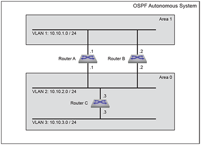
The OSPF Autonomous System in Example 1 contains two areas connected through two routers. The backbone area also contains an internal router that connects two subnets.
Example 1 Topology
OSPFv2 Example 1 displays the Example 1 topology. Two ABRs, Router A and Router B, connect Area 0 and Area 1. Router C is an internal router connecting two subnets in Area 0.
Area 1 Configuration
- Router A: The subnet 10.10.1.0/24 is accessed through VLAN 1.
- Router B: The subnet 10.10.1.0/24 is accessed through VLAN 1.
- Each router uses simple authentication with the password abcdefgh.
- Designated Router (DR): Router A.
- Backup Designated Router (BDR): Router B.
- Each router defines an interface cost of 10.
- Router priority is not specified for either router on Area 1.
Area 0 ABR Configuration
- Router A: The subnet 10.10.2.0/24 is accessed through VLAN 2.
- Router B: The subnet 10.10.2.0/24 is accessed through VLAN 2.
- Designated Router (DR): Router B.
- Backup Designated Router (BDR): Router A.
- Each router uses simple authentication with the password ijklmnop.
- Each router defines an interface cost of 20.
- Each router defines a retransmit-interval of 10.
- Each router defines a transmit-delay of 2.
- Router priority is specified so that Router B will be elected as the Designated Router.
Area 0 IR Configuration
- Router C: The subnet 10.10.2.0/24 is accessed through VLAN 2.
- Router C: The subnet 10.10.3.0/24 is accessed through VLAN 3.
- The subnet 10.10.2.0/24 link is configured as follows:
- Interface cost of 20.
- Retransmit-interval of 10.
- Transmit-delay of 2.
- The subnet 10.10.3.0/24 link is configured as follows:
- Interface cost of 20.
- Dead interval of 80 seconds.
Example 1 Code
The following code examples configure the OSPFv2 instances on the three switches.
OSPFv2 Configuration Example 2
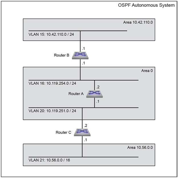
The AS in Example 2 contains three areas. Area 0 connects to the other areas through different routers. The backbone area contains an internal router that connects two subnets. Area 0 is normal; the other areas are stub areas.
Example 2 Topology
OSPFv2 Example 2 displays the Example 2 topology. One ABR (Router B) connects Area 0 and Area 10.42.110.0; another ABR (Router C) connects Area 0 and Area 36.56.0.0. Router A is an internal router connecting two subnets in Area 0.
Area 10.42.110.0 Configuration
- Router B: The subnet 10.42.110.0 is accessed through VLAN 15.
- Router B uses simple authentication with the password abcdefgh.
- Each router defines a interface cost of 10.
Area 10.56.0.0 Configuration
- Router C: The subnet 10.56.0.0 is accessed through VLAN 21.
- Router C uses simple authentication with the password ijklmnop.
- Each router defines a interface cost of 20.
Area 0 ABR Configuration
- Router B: The subnet 10.119.254.0/24 is accessed through VLAN 16.
- Router C: The subnet 10.119.251.0/24 is accessed through VLAN 20.
- Designated Router (DR): Router B.
- Backup Designated Router (BDR): Router C.
- Each ABR uses simple authentication with the password ijklmnop.
- Each router defines an interface cost of 20.
- Each router defines a retransmit-interval of 10.
- Each router defines a transmit-delay of 2.
Area 0 IR Configuration
- Router A: The subnet 10.119.254.0/24 is accessed through VLAN 16.
- Router A: The subnet 10.119.251.0/24 is accessed through VLAN 20.
- The subnet 10.42.110.0 is configured as follows:
- Interface cost of 10.
- The subnet 10.56.0.0/24 is configured as follows:
- Interface cost of 20.
- Retransmit-interval of 10.
- Transmit-delay of 2.
Example 2 Code
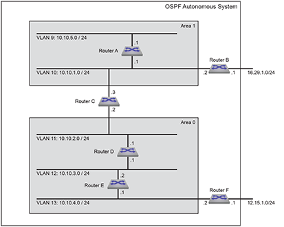
OSPFv2 Configuration Example 3
- Area 0: Backbone area contains two internal routers connecting three subnets, one ASBR, and one ABR that connects to Area 1.
- Area 1: NSSA contains one internal router, one ASBR, and one ABR that connects to the backbone.
Example 3 Topology
OSPFv2 Example 3 displays the Example 3 topology. One ABR connects Area 0 and Area 1. Router C is an ABR that connects the areas. Router A is an internal router connecting two subnets in Area 1. Router D and Router E are internal routers connecting subnets in Area 0. Router B and Router F are ASBRs connecting static routes outside the AS to Area 1 and Area 0, respectively.
Area 0 ABR Configuration
- Router C: The subnet 10.10.2.0/24 is accessed through VLAN 11.
- Authentication is not configured on the interfaces.
- All interface OSPFv2 parameters are set to their default values.
Area 0 IR Configuration
- Router D: The subnet 10.10.2.0/24 is accessed through VLAN 11.
- Router D: The subnet 10.10.3.0/24 is accessed through VLAN 12.
- Router E: The subnet 10.10.3.0/24 is accessed through VLAN 12.
- Router E: The subnet 10.10.4.0/24 is accessed through VLAN 13.
- All interface OSPFv2 parameters are set to their default values.
Area 0 ASBR Configuration
- Router F: The subnet 10.10.4.0/24 is accessed through Router F.
- Router F: The subnet 12.15.1.0/24 is accessed through VLAN 14.
- All interface OSPFv2 parameters are set to their default values.
Area 1 ABR Configuration
- Router C: The subnet 10.10.1.0/24 is accessed through VLAN 10.
- Authentication is not configured on the interface.
- All interface OSPFv2 parameters are set to their default values.
Area 1 IR Configuration
- Router A: The subnet 10.10.1.0/24 is accessed through VLAN 10.
- Router A: The subnet 10.10.5.0/24 is accessed through Router A.
- All interface OSPFv2 parameters are set to their default values.
Area 1 ASBR Configuration
- Router B: The subnet 10.10.1.0/24 is accessed through VLAN 10.
- Router B: The subnet 16.29.1.0/24 is accessed through VLAN 15.
- All interface OSPFv2 parameters are set to their default values.
Example 3 Code
OSPFv2 Commands
Global Configuration Mode
Interface Configuration Mode
Router-OSPFv2 Configuration Mode
- adjacency exchange-start threshold (OSPFv2)
- area default-cost (OSPFv2)
- area filter (OSPFv2)
- area nssa (OSPFv2)
- area nssa default-information-originate (OSPFv2)
- area nssa no-summary (OSPFv2)
- area not-so-stubby lsa type-7 convert type-5 (OSPFv2)
- area range (OSPFv2)
- area stub (OSPFv2)
- auto-cost reference-bandwidth (OSPFv2)
- compatible (OSPFv2)
- default-information originate (OSPFv2)
- distance ospf (OSPFv2)
- dn-bit-ignore (OSPFv2)
- log-adjacency-changes (OSPFv2)
- max-lsa (OSPFv2)
- max-metric router-lsa (OSPFv2)
- maximum-paths (OSPFv2)
- network area (OSPFv2)
- no area (OSPFv2)
- passive-interface default (OSPFv2)
- passive-interface (OSPFv2)
- point-to-point routes (OSPFv2)
- redistribute (OSPFv2)
- redistribute ospf instance
- router-id (OSPFv2)
- shutdown (OSPFv2)
- summary-address
- timers lsa rx min interval (OSPFv2)
- timers lsa tx delay initial (OSPFv2)
- timers spf delay initial (OSPFv2)
TCAM Profile Configuration Mode
Display and Clear Commands
- clear ip ospf neighbor
- show hardware tcam profile
- show ip ospf
- show ip ospf border-routers
- show ip ospf database database-summary
- show ip ospf database <link state list>
- show ip ospf database <link-state details>
- show ip ospf interface
- show ip ospf interface brief
- show ip ospf lsa-log
- show ip ospf neighbor
- show ip ospf neighbor adjacency-changes
- show ip ospf neighbor state
- show ip ospf neighbor summary
- show ip ospf request queue
- show ip ospf retransmission queue
- show ip ospf spf-log
- show line system dom thresholds
- show line system status
auto-cost reference-bandwidth (OSPFv2)
The auto-cost reference-bandwidth command is a factor in the formula that calculates the default OSPFv2 cost for Ethernet interfaces.
OSPFv2-cost = (auto-cost value * 1 Mbps) / interface bandwidth.
The switch uses a minimum OSPFv2-cost of 1. The switch rounds down all non-integer results.
- if auto-cost = 100, then OSPFv2-cost = 100 Mbps / 10 Gbps = 0.01, and the default cost is set to 1.
- if auto-cost = 59000, then OSPFv2-cost = 59000 Mbps / 10 Gbps = 5.9, and the default cost is set to 5.
The no auto-cost reference-bandwidth and default auto-cost reference-bandwidth command removes the auto-cost reference-bandwidth command from running-config. When this parameter is not set, the default cost for Ethernet interfaces is the default ip ospf cost value of 10.
Command Mode
Router-OSPF Configuration
Command Syntax
auto-cost reference-bandwidth rate
no auto-cost reference-bandwidth rate
default auto-cost reference-bandwidth rate
Parameter
rate Values range from 1 to 4294967. Default is 100.
Examples
To configure a default cost of 20 on 10G Ethernet interfaces:
adjacency exchange-start threshold (OSPFv2)
The adjacency exchange-start threshold command sets the exchange-start options for an OSPF instance.
The no adjacency exchange-start threshold and default adjacency exchange-start threshold command resets the default by removing the corresponding a adjacency exchange-start threshold command from running-config.
Command Mode
Router-OSPF Configuration
Command Syntax
adjacency exchange-start threshold peers
no adjacency exchange-start threshold
default adjacency exchange-start threshold
Parameter
peers Value ranges from 1- 4294967295. Default value is 10.
Example
switch(config)# router ospf 6
switch(config-router-ospf)# adjacency exchange-start threshold 20045623
switch(config-router-ospf)#area default-cost (OSPFv2)
The area default-cost command specifies the cost for the default summary routes sent into a specified area. The default-cost is set to 10.
The no area default-cost and default area default-cost command resets the default-cost value of the specified area to 10 by removing the corresponding area default-cost command from running-config. The no area (OSPFv2) command removes all area commands for the specified area from running-config, including the area default-cost command.
Command Mode
Router-OSPF Configuration
Command Syntax
area area_id default-cost def_cost
no area area_id default-cost def_cost
default area area_id default-cost def_cost
- area_id Area number: 0 to 4294967295 or 0.0.0.0 to 255.255.255.255 running-config stores value in dotted decimal notation.
- def_cost Value ranges from 1 to 65535. Default value is 10.
Example
switch(config)# router ospf 6
switch(config-router-ospf)# area 23 default-cost 15
switch(config-router-ospf)#area filter (OSPFv2)
The area filter command prevents an area from receiving Type 3 Summary LSAs and Type 4 APSR Summary LSAs from a specified subnet.
The no area filter and default area filter commands remove the specified area filter command from running-config. The no area command (see no area (OSPFv2) removes all area commands for the specified area from running-config, including area filter commands.
Command Mode
Router-OSPF Configuration
Command Syntax
area area_id filter net_addr
no area area_id filter net_addr
default area area_id filter net_addr
- area_id Area number. 0 to 4294967295 or 0.0.0.0 to 255.255.255.255. running-config stores value in dotted decimal notation.
- net_addr Network IP address. Entry formats include address-prefix (CIDR) and address-mask. running-config stores value in CIDR notation.
Example
switch(config)# router ospf 6
switch(config-router-ospf)# area 2 filter 10.1.1.0/24
switch(config-router-ospf)#area not-so-stubby lsa type-7 convert type-5 (OSPFv2)
The area not-so-stubby lsa type-7 convert type-5 command configures the switch to always translate Type-7 Link-State Advertisement (LSAs) to Type-5 LSAs.
The no area not-so-stubby lsa type-7 convert type-5 and no area not-so-stubby lsa type-7 convert type-5 commands allow LSAs to be translated dynamically by removing the no area not-so-stubby lsa type-7 convert type-5 command from running-config.
Command Mode
Router-OSPF Configuration
Command Syntax
area area_id not-so-stubby lsa type-7 convert type-5
no area area_id not-so-stubby lsa type-7 convert type-5
default area area_id not-so-stubby lsa type-7 convert type-5
Parameters
- Valid formats: integer 1 to 4294967295 or dotted decimal 0.0.0.1 to 255.255.255.255.
- Area 0 (or 0.0.0.0) is not configurable; it is always normal.
- running-config stores value in dotted decimal notation.
Example
switch(config-router-ospf)# area 3 not-so-stubby lsa type-7 convert type-5
switch(config-router-ospf)#area nssa (OSPFv2)
The area nssa command configures an OSPFv2 area as a Not-So-Stubby Area (NSSA). All routers in an AS must specify the same area type for identically numbered areas.
NSSA ASBRs advertise external LSAs that are part of the area, but do not advertise external LSAs from other areas.
Areas are normal by default; area type configuration is required only for stub NSSA areas. Area 0 is always a normal area and cannot be configured through this command.
The no area nssa command configures the specified area as a normal area by removing the specified area nssa command from running-config.
Command Mode
Router-OSPF Configuration
Command Syntax
area area_id nssa [TYPE]
no area area_id nssa [TYPE]
default area area_id nssa [TYPE]
- area_id All parameters except
area_id can be placed in any order.
- Valid formats: integer 1 to 4294967295 or dotted decimal 0.0.0.1 to 255.255.255.255.
- Area 0 (or 0.0.0.0) is not configurable; it is always normal.
- running-config stores value in dotted decimal notation.
- TYPE Area type. Values include:
- no parameter
- nssa-only
Example
switch(config-router-ospf)# area 3 nssa nssa-only
switch(config-router-ospf)#area nssa default-information-originate (OSPFv2)
The default area nssa default-information-originate command sets default route origination for the Not-So-Stubby Area (NSSA), allowing the redistribute policy to advertise a default route if one is present. The resulting OSPF behavior depends on the presence of an installed static default route and on whether static routes are redistributed in OSPF (using the redistribute (OSPFv2) command). The no area nssa default-information-originate command disables advertisement of the default route for the NSSA regardless of the redistribute policy. See Advertisement of Default Route for details.
Areas are normal by default; area type configuration is required only for stub and NSSA areas. Area 0 is always a normal area and cannot be configured through this command.
- Normal areas: advertisement of the default route is configured for all normal areas using the default-information originate (OSPFv2) command.
- Stub areas: the default route is automatically advertised in stub areas and cannot be configured.
- Not So Stubby Areas (NSSAs): advertisement of the default route is
configured per area using the area
nssa default-information-originate (OSPFv2) or area nssa no-summary (OSPFv2) command.
Table 1. Advertisement of Default Route Static Default Route Installed Redistribute Static Command Form Advertise in ABR Advertise in ASBR no no default or no no no no no standard yes no no yes default yes yes no yes no no no no yes standard yes no yes no default or no no no yes no standard yes yes yes yes default yes yes yes yes no no no yes yes standard yes yes
Command Mode
Router-OSPF Configuration
Command Syntax
area area_id nssa default-information-originate [VALUE][TYPE][EXCL]
no area area_id nssa default-information-originate
default area area_id nssa default-information-originate
- area_id All parameters except
area_id can be placed in any order.
- Valid formats: integer 1 to 4294967295 or dotted decimal 0.0.0.1 to 255.255.255.255.
- Area 0 (or 0.0.0.0) is not configurable; it is always normal.
- running-config stores value in dotted decimal notation.
- VALUE Values include:
- no parameter Default value of 1.
- metric 1-65535.
- TYPE Values include:
- no parameter.
- metric-type 1-2.
- EXCL Values include:
- no parameter.
- nssa-only.
Example
switch(config-router-ospf)# area 3 nssa default-information-originate nssa-only
switch(config-router-ospf)#area nssa no-summary (OSPFv2)
The area nssa no-summary command configures the switch stop importing type-3 summary LSAs into the not-so-stubby area and sets the default summary route into theNot-So-Stubby Area (NSSA) in order to reach the inter-area prefixes.
The no area nssa no-summary anddefault area nssa no-summary commands allow type-3 summary LSAs into the NSSA area.
The no area nssa and default area nssa commands configure the specified area as a normal area.
Command Mode
Router-OSPF Configuration
Command Syntax
area area_id nssa no-summary
no area area_id nssa no-summary
default area area_id nssa no-summary
Parameters
- Valid formats: integer 1 to 4294967295 or dotted decimal 0.0.0.1 to 255.255.255.255.
- Area 0 (or 0.0.0.0) is not configurable; it is always normal.
- running-config stores value in dotted decimal notation.
- This command directs the device not to import type-3 summary LSAs into the
NSSA area
switch(config)# router ospf 6 switch(config-router-ospf)# area 1.1.1.1 nssa no-summary switch(config-router-ospf)# -
This command directs the device to import type-3 summary LSAs into the NSSA area.
switch(config)# router ospf 6 switch(config-router-ospf)# no area 1.1.1.1 nssa no-summary switch(config-router-ospf)#
area range (OSPFv2)
The area range command configures OSPF Area Border Routers (ABRs) to consolidate or summarize routes, to set the cost setting routes, and to suppress summary route advertisements.
The no area (OSPFv2) command removes all area commands for the specified area from running-config.
Command Mode
Router-OSPF Configuration
Command Syntax
area area_id range net_addr [ADVERTISE_SETTING][COST_SETTING]
no area area_id range net_addr [ADVERTISE_SETTING][COST_SETTING]
default area area_id range net_addr [ADVERTISE_SETTING][COST_SETTING]
- area_id Area number. 0 to 4294967295 or 0.0.0.0 to 255.255.255.255 running-config stores value in dotted decimal notation.
- net_addr.
- ADVERTISE_SETTING Values include:
- no parameter
- advertise
- not-advertise
- Values include:
- no parameter
- cost range_cost Value ranges from 1 to 65535.
- The network area command assigns two subnets to an
area. The area range command summarizes the
addresses, which the ABR advertises in a single
LSA.
switch(config)# router ospf 6 switch(config-router-ospf)# network 10.1.25.80 0.0.0.240 area 5 switch(config-router-ospf)# network 10.1.25.112 0.0.0.240 area 5 switch(config-router-ospf)# area 5 range 10.1.25.64 0.0.0.192 switch(config-router-ospf)# -
The network area command assigns a subnet to an area, followed by an area range command that suppresses the advertisement of that subnet.
switch(config-router-ospf)# network 10.12.31.0/24 area 5 switch(config-router-ospf)# area 5 range 10.12.31.0/24 not-advertise switch(config-router-ospf)#
area stub (OSPFv2)
The area stub command sets the area type of an OSPF area to stub. All devices in an Area Stub (AS) must specify the same area type for identically numbered areas.
The no area stub command remove the specified stub area from the OSPFv2 instance by deleting all area stub commands from running-config for the specified area.
The no area stub command configures the specified area as a normal area.
Command Mode
Router-OSPF Configuration
Command Syntax
area area_id stub [summarize]
no area area_id stub [summarize]
default area area_id stub [summarize]
- area_id Area number.
- Valid formats: integer 1 to 4294967295 or dotted decimal 0.0.0.1 to 255.255.255.255.
- Area 0 (or 0.0.0.0) is not configurable; it is always normal.
- running-config stores value in dotted decimal notation.
- summarize Area type. Values include:
- no parameter
- no-summary
- These commands configure area 45 as a stub
area.
switch(config)# router ospf 3 switch(config-router-ospf)# area 45 stub switch(config-router-ospf)# - This command configures area 10.92.148.17 as a
stub
area.
switch(config-router-ospf)# area 10.92.148.17 stub switch(config-router-ospf)#
clear ip ospf neighbor
The clear ip ospf command clears the neighbors statistics per interface.
Command Mode
Privileged EXEC
Command Syntax
clear ip ospf [PROCESS_ID] neighbor [LOCATION][VRF_INSTANCE]
- PROCESS_ID OSPFv2 process ID. Values include:
- no parameter
- 1 to 65535.
- LOCATIONIP Address or interface peer group name. Values
include:
- * clears all OSPF IPv4 neighbors.
- ipv4_addr
- ethernet e_num
- loopback l_num
- port-channel p_num
- vlan v_num
- VRF_INSTANCE Specifies the VRF instance.
- vrf vrf_name configures the vrf_name instance.
-
This command resets all OSPF neighbor statistics.
switch# clear ip ospf neighbor * switch# -
This command resets the OSPF neighbor statistics for the specified ethernet 3 interface.
switch# clear ip ospf neighbor ethernet 3 switch#
compatible (OSPFv2)
The compatible command allows the selective disabling of compatibility with RFC 2328.
The no compatible and default compatible commands reverts OSPF to RFC 2328 compatible and removes the compatible statement from running-config.
Command Mode
Router-OSPF Configuration
Command Syntax
compatible rfc1583
no compatible rfc1583
default compatible rfc1583
- This command sets the OSPF compatibility list with RFC
1583.
switch(config)# router ospf 6 switch(config-router-ospf)# compatible rfc1583 switch(config-router-ospf)# - This command disables RFC 1583
compatibility.
switch(config)# router ospf 6 switch(config-router-ospf)# no compatible rfc1583 switch(config-router-ospf)#
default-information originate (OSPFv2)
The default-information originate command enables default route origination for normal areas. The user user may configure the metric value and metric type used in LSAs. The always option will cause the ASBR to create and advertise a default route whether or not one is configured.
The no default-information originate command prevents the advertisement of the default route. The default default-information originate command enables default route origination with default values (metric type 2, metric=1).
Command Mode
Router-OSPF Configuration
Command Syntax
default-information originate [FORCE][VALUE][TYPE][MAP]
no default-information originate
default default-information originate
Parameters
- FORCE Advertisement forcing option. Values
include:
- no parameter
- always
- VALUE Values include:
- no parameter
- metric 1-65535
- TYPE Values include:
- no parameter
- metric-type 1-2
- MAP Sets attributes in the LSA based on a route map. Values
include:
- no parameter
- route-map map_name.
- These commands always advertise the OSPFv2 default route regardless of
whether the switch has a default route
configured.
switch(config)# router ospf 1 switch((config-router-ospf)# default-information originate always switch(config-router-ospf)# show active router ospf 1 default-information originate always - These commands advertise a default route with a metric of
100 and an external metric type of
1 if a default route is
configured.
switch(config)# router ospf 1 switch((config-router-ospf)# default-information originate metric 100 metric-type 1
distance ospf (OSPFv2)
The distance ospf command specifies the administrative distance for intra-area, inter-area, or external OSPF routes. The command must be issued separately for each route type being configured. The default administrative distance for all routes is 110.
The no distance ospf and default distance ospf commands remove the corresponding distance ospf command from running-config, returning the OSPFv2 administrative distance setting for the specified route type to the default value of 110.
Command Mode
Router-OSPF Configuration
Command Syntax
distance ospf [external | inter-area | intra-area]
no distance ospf [external | inter-area | intra-area]
default distance ospf [external | inter-area | intra-area]
- external Sets administrative distance for external routes.
- inter-area Sets administrative distance for inter-area routes.
- intra-area sSets administrative distance for intra-area routes.
- distance Values range from 1 to 255. Default value is 110 for all types.
Example
switch(config)# router ospf 6
switch(config-router-ospf)# distance ospf intra-area 85
switch(config-router-ospf)#distribute-list in
A distribute list uses a route map or prefix list to filter specific routes from incoming OSPF LSAs. Filtering occurs after SPF calculation. The filtered routes are not installed on the switch, but are still included in LSAs sent by the switch. The distribute-list in command creates a distribute list in the configuration mode OSPF instance.
If a prefix list is used, destination prefixes that do not match the prefix list will not be installed. If a route map is used, routes may be filtered based on address, next hop, or metric. OSPF external routes may also be filtered by metric type or tag.
The no distribute-list in and default distribute-list in commands remove the distribute-list in command from running-config.
Command Mode
Router-OSPF Configuration
Command Syntax
distribute-list {prefix-list | route-map} list_name in
no distribute-list {prefix-list | route-map}
default distribute-list {prefix-list | route-map}
- prefix-list Specifies a prefix-list as the filter.
- route-map Specifies a route-map as the filter.
- list_name The name of the prefix-list or route-map used to filter routes from incoming LSAs.
Example
switch(config)# router ospf 5
switch(config-router-ospf)# distribute-list prefix-list dist_list1 in
switch(config-router-ospf)#dn-bit-ignore (OSPFv2)
The dn-bit-ignore command results in the DN bit in Type 3 Summary LSAs to be ignored during the Shortest Path First (SPF) calculations.
The no dn-bit-ignore and default dn-bit-ignore commands result in the DN bit in Type 3 Summary LSAs to not be ignored during SPF calculations.
Command Mode
Router-OSPF Configuration
Command Syntax
dn-bit-ignore
no dn-bit-ignore
default dn-bit-ignore
- This command ignores the DN
bit.
switch(config)# router ospf 6 switch(config-router-ospf)# dn-bit-ignore switch(config-router-ospf)# -
This command causes the DN bit not to be ignored.
switch(config)# router ospf 6 switch(config-router-ospf)# no dn-bit-ignore switch(config-router-ospf)#
interface Tunnel
OSPF packets by default are sent with Time to Live (TTL) value 1. This may not work in tunnel scenarios where the peer tunnel end point could be more than one hop away. It is recommended to explicitly configure TTL on the tunnel interface. TTL configuration is allowed only if path-mtu-discovery is configured.
Command Mode
Configuration mode
Command Syntax
interface Tunnel Tunnel No
Parameter
Tunnel No Tunnel number.
(config)# interface Tunnel 5
(config-if-Tu0)# tunnel path-mtu-discovery
(config-if-Tu0)# tunnel ttl 5ip ospf area
The ip ospf area command enables OSPFv2 on an interface and associates the area to the interface.
The no ip ospf area and default ip ospf area commands disable OSPFv2 on the configuration mode interface and remove the configured area from the system.
Command Mode
Interface-Ethernet Configuration
Interface-Loopback Configuration
Interface-Port-Channel Configuration
Interface-VLAN Configuration
Command Syntax
ip ospf area area_id
no ip ospf area area_id
default ip ospf area area_id
Parameters
area_id The area ID. The valid values are 0 to 4294967295 or a decimal range between 0.0.0.0 and 255.255.255.255.
Example
switch(config)# Interface ethernet 2
switch(config-if-Et2)# ip address 1.0.0.1/24
switch(config-if-Et2)# ip ospf area 1.1.1.1
router ospf 1ip ospf authentication
The ip ospf authentication command enables OSPFv2 authentication for the configuration mode interface..
The no ip ospf authentication and default ip ospf authentication commands disable OSPFv2 authentication on the configuration mode interface by removing the corresponding ip ospf authentication command from running-config.
Command Mode
Interface-Ethernet Configuration
Interface-Port-Channel Configuration
Interface-VLAN Configuration
Command Syntax
ip ospf authentication [METHOD]
no ip ospf authentication
default ip ospf authentication
Parameters
- no parameter
- message-digest
- This command enables simple authentication on vlan
12.
switch(config)# interface vlan 12 switch(config-if-vl12)# ip ospf authentication switch(config-if-vl12)# - This command enables message-digest authentication on vlan
12.
switch(config-if-vl12)# ip ospf authentication message-digest switch(config-if-vl12)#
ip ospf authentication-key
The ip ospf authentication-key command configures the OSPFv2 authentication password for the configuration mode interface.
The no ip ospf authentication-key and default ip ospf authentication-key commands removes the OSPFv2 authentication password from the configuration mode interface by removing the corresponding ip ospf authentication-key command from running-config.
Command Mode
Interface-Ethernet Configuration
Interface-Port-Channel Configuration
Interface-VLAN Configuration
Command Syntax
ip ospf authentication-key [ENCRYPT_TYPE] key_text
no ip ospf authentication-key
default ip ospf authentication-key
- ENCRYPT_TYPE Encryption level of the
key_text parameter. Values include:
- no parameter the key_text is in clear text.
- 0 key_text is in clear text. Equivalent to no parameter.
- 7 key_text is MD5 encrypted.
- key_text the authentication-key password.
Example
switch(config)# interface vlan 12
switch(config-if-Vl12)# ip ospf authentication-key 0 code123
switch(config-if-Vl12)# show active
interface Vlan12
ip ospf authentication-key 7 baYllFzVbcx4yHq1IhmMdw==
switch(config-if-Vl12)#The running-config stores the password as an encrypted string.
ip ospf cost
- Ethernet: determined by the auto-cost reference-bandwidth (OSPFv2) command.
- Port channel: 10.
- VLAN: 10.
The no ip ospf cost and default ip ospf cost commands restore the default OSPFv2 cost for the configuration mode interface by removing the corresponding ip ospf cost command from running-config.
Command Mode
Interface-Ethernet Configuration
Interface-Loopback Configuration
Interface-Port-Channel Configuration
Interface-VLAN Configuration
Command Syntax
ip ospf cost interface_cost
no ip ospf cost
default ip ospf cost
Parameter
interface_cost Value ranges from 1 to 65535; default is 10.
Example
switch(config)# interface vlan 2
switch(config-if-Vl2)# ip ospf cost 15
switch(config-if-Vl2)#ip ospf dead-interval
The ip ospf dead-interval command configures the dead interval for the configuration mode interface.
The no ip ospf dead-interval and default ip ospf dead-interval commands restore the default dead interval of 40 seconds on the configuration mode interface by removing the corresponding ip ospf dead-interval command from running-config.
Command Mode
Interface-Ethernet Configuration
Interface-Port-Channel Configuration
Interface-VLAN Configuration
Command Syntax
ip ospf dead-interval time
no ip ospf dead-interval
default ip ospf dead-interval
Parameter
time Value ranges from 1 to 8192; default is 40.
Example
switch(config)# interface vlan 4
switch(config-if-Vl4)# ip ospf dead-interval 120
switch(config-if-Vl4)#ip ospf disabled
The ip ospf disabled command disables OSPFv2 on the configuration mode interface without disrupting the OSPFv2 configuration. When OSPFv2 is enabled on the switch, the it is also enabled by default on all interfaces.
The OSPFv2 instance is disabled on the entire switch with the shutdown (OSPFv2) command.
The no ip ospf disabled and default ip ospf disabled commands enable OSPFv2 on the configuration mode interface by removing the corresponding ip ospf disabled command from running-config.
Command Mode
Interface-Ethernet Configuration
Interface-Port-Channel Configuration
Interface-VLAN Configuration
Command Syntax
ip ospf disabled
no ip ospf disabled
default ip ospf disabled
- This command shuts down OSPFv2 activity on vlan
5.
switch(config)# interface vlan 5 switch(config-if-Vl5)# ip ospf disabled switch(config-if-Vl5)# - This command resumes OSPFv2 activity on vlan
5.
switch(config-if-Vl5)# no ip ospf disabled switch(config-if-Vl5)#
ip ospf hello-interval
The ip ospf hello-interval command configures the OSPFv2 hello interval for the configuration mode interface.
The same hello interval should be specified for Each OSPFv2 neighbor, and should not be longer than any neighbors dead interval.
The no ip ospf hello-interval and default ip ospf hello-interval commands restore the default hello interval of 10 seconds on the configuration mode interface by removing the ip ospf hello-interval command from running-config.
Command Mode
Interface-Ethernet Configuration
Interface-Port-Channel Configuration
Interface-VLAN Configuration
Command Syntax
ip ospf hello-interval time
no ip ospf hello-interval
default ip ospf hello-interval
Parameter
time Hello interval (seconds). Values range from 1 to 8192; default is 10.
Example
switch(config)# interface vlan 2
switch(config-if-Vl2)# ip ospf hello-interval 30
switch(config-if-Vl2)#ip ospf message-digest-key
The ip ospf message-digest-key command configures a message digest authentication key for the configuration mode interface.
The no ip ospf message-digest-key and default ip ospf message-digest-key commands remove the message digest authentication key for the specified key ID on the configuration mode interface by deleting the corresponding ip ospf message-digest-key command from running-config.
Command Mode
Interface-Ethernet Configuration
Interface-Port-Channel Configuration
Interface-VLAN Configuration
Command Syntax
ip ospf message-digest-key key_id md5 ENCRYPT_TYPE key_text
no ip ospf message-digest-key key_id
default ip ospf message-digest-key key_id
- key_id Key ID number. Value ranges from 1 to 255.
- ENCRYPT_TYPE Encryption level of the
key_text parameters. Values include:
- no parameter
- 0 key_text
- 7 key_text
- key_text message key (password).
Example
switch(config)# interface vlan 12
switch(config-if-vl12)# ip ospf message-digest-key 23 md5 0 code123
switch(config-if-vl12)#The running-config stores the password as an encrypted string.
ip ospf network point-to-point
The ip ospf network point-to-point command sets the configuration mode interface as a point-to-point link. By default, interfaces are configured as broadcast links.
The no ip ospf network and default ip ospf network commands set the configuration mode interface as a broadcast link by removing the corresponding ip ospf networkcommand from running-config.
Command Mode
Interface-Ethernet Configuration
Interface-Port-Channel Configuration
Interface-VLAN Configuration
Command Syntax
ip ospf network point-to-point
no ip ospf network
default ip ospf network
- These commands configure ethernet interface 10 as
a point-to-point
link.
switch(config)# interface ethernet 10 switch(config-if-Etl0)# ip ospf network point-to-point switch(config-if-Etl0)# - This command restores ethernet interface 10 as a
broadcast
link.
switch(config-if-Etl0)# no ip ospf network switch(config-if-Etl0)#
ip ospf retransmit-interval
The ip ospf retransmit-interval command configures the link state advertisement retransmission interval for the interface.
The no ip ospf retransmit-interval and default ip ospf retransmit-interval commands restore the default retransmission interval of 5 seconds on the configuration mode interface by removing the corresponding ip ospf retransmit-interval command from running-config.
Command Mode
Interface-Ethernet Configuration
Interface-Port-Channel Configuration
Interface-VLAN Configuration
Command Syntax
ip ospf retransmit-interval period
no ip ospf retransmit-interval
default ip ospf retransmit-interval
Parameter
period Retransmission interval (seconds). Value ranges from 1 to 8192; default is 5.
Example
switch(config)# interface vlan 3
switch(config-if-Vl3)# ip ospf retransmit-interval 15
switch(config-if-Vl3)#ip ospf router-id output-format hostnames
The no ip ospf router-id output-format hostnames and default ip ospf router-id output-format hostnames commands remove the ip ospf router-id output-format hostnames command from running-config, restoring the default behavior of displaying OSPFv2 router IDs by their numeric value.
Command Mode
Global Configuration
Command Syntax
ip ospf router-id output-format hostnames
no ip ospf router-id output-format hostnames
default ip ospf router-id output-format hostnames
Example
This command programs the switch to display OSPFv2 router IDs by the corresponding DNS name in subsequent show commands.
switch(config)# ip ospf router-id output-format hostnames
switch(config)#ip ospf transmit-delay
The ip ospf transmit-delay command configures the transmission delay for OSPFv2 packets over the configuration mode interface.
The no ip ospf transmit-delay and default ip ospf transmit-delay commands restore the default transmission delay (1 second) on the configuration mode interface by removing the corresponding ip ospf transmit-delay command from running-config.
Command Mode
Interface-Ethernet Configuration
Interface-Port-Channel Configuration
Interface-VLAN Configuration
Command Syntax
ip ospf transmit-delay trans
no ip ospf transmit-delay
default ip ospf transmit-delay
Parameter
trans LSA transmission delay (seconds). Value ranges from 1 to 8192; default is 1.
Example
switch(config)# interface vlan 6
switch(config-if-Vl6)# ip ospf transmit-delay 5
switch(config-if-Vl6)#ip ospf priority
The ip ospf priority command configures OSPFv2 router priority for the configuration mode interface..
The no ip ospf priority and default ip ospf priority commands restore the default priority (1) on the configuration mode interface by removing the corresponding ip ospf priority command from running-config.
Command Mode
Interface-Ethernet Configuration Interface-Port-Channel Configuration Interface-VLAN Configuration
Command Syntax
ip ospf priority priority_level
no ip ospf priority
default ip ospf priority
Parameter
priority_level priority level. Value ranges from 0 to 255. Default value is 1.
- This command configures a router priority of 15
for vlan
8.
switch(config)# interface vlan 8 switch(config-if-Vl8)# ip ospf priority 15 switch(config-if-Vl8)# - This command restores the router priority of 1 for
vlan
7.
switch(config)# interface vlan 7 switch(config-if-Vl7)# no ip ospf priority switch(config-if-Vl7)#
line system
The line system command places the switch in the OSPF - Line System configuration mode.
The no line system command removes the Line System configurations from the running-config.
Command Mode
Global Configuration Mode
Command Syntax
line system
no line system
Parameters
- port
number Transceiver slot number. Value ranges from
1 - 66.
- The following parameters are allowed under LS port mode:
- booster Booster settings
- pre-amp Pre-amp settings
- The following parameters are allowed under LS port mode:
Example
switch# config
switch(config)# line system
switch(config-ls)#log-adjacency-changes (OSPFv2)
The log-adjacency-changes command enables syslog messages to be sent when it detects OSPFv2 link state changes or when it detects that a neighbor has gone up or down. Log message sending is enabled by default.
The default log-adjacency-changes command restores the default state by removing the log-adjacency-changes statement from running-config.
The default option (sending a message only when a neighbor goes up or down) is active when running-config does not contain any form of the command. Entering the command in any form replaces the previous command state in running-config.
The no log-adjacency-changes disables link state change syslog reporting.
The default log-adjacency-changes command restores the default state by removing the log-adjacency-changes detail or no log-adjacency-changes statement from running-config.
Command Mode
Router-OSPF Configuration
Command Syntax
log-adjacency-changes detail
no log-adjacency-changes
default log-adjacency-changes
- This command configures the switch to send a syslog message when a neighbor
goes up or down.
switch(config)# router ospf 6 switch(config-router-ospf)# log-adjacency-changes switch(config-router-ospf)#- After entering the command, show active
does not display a log-adjacency-changes
statement.
switch(config-router-ospf)# show active router ospf 1 switch(config-router-ospf)#
- After entering the command, show active
does not display a log-adjacency-changes
statement.
- This command configures the switch to send a Syslog message when it detects
any link state
change.
switch(config-router-ospf)# log-adjacency-changes detail switch(config-router-ospf)#- After entering the command, show active
displays a log-adjacency-changes detail
command.
switch(config-router-ospf)# show active router ospf 1 switch(config-router-ospf)# log-adjacency-changes detail switch(config-router-ospf)#
- After entering the command, show active
displays a log-adjacency-changes detail
command.
maximum-paths (OSPFv2)
The maximum-paths command controls the number of parallel routes that OSPFv2 supports. The default maximum is 16 paths.
The no maximum-paths and default maximum-paths commands restore the maximum number of parallel routes that OSPFv2 supports on the switch to the default value of 16 by placing the maximum-paths 16 statement in running-config.
Command Mode
Router-OSPF Configuration
Command Syntax
maximum-paths paths
no maximum-paths
default maximum-paths
Parameters
paths Maximum number of parallel routes.
- Arad: Value ranges from 1 to 128. Default
value is 128.
- FM6000: Value ranges from 1 to 32. Default value is 32.
- PetraA: Value ranges from 1 to 16. Default value is 16.
- Trident: Value ranges from 1 to 32. Default value is 32.
- Trident II: Value ranges from 1 to 128. Default value is 128.
Example
switch(config)# router ospf 6
switch(config-router-ospf)# maximum-paths 12
switch(config-router-ospf)#max-lsa (OSPFv2)
- Warning: the switch logs OSPF MAXLSAWARNING if the LSDB contains a specified percentage of the LSA maximum.
- Temporary shutdown: when the LSDB exceeds the LSA maximum, OSPFv2 is disabled and does not accept or acknowledge new LSAs. The switch re-starts OSPFv2 after a specified period (the default is five minutes).
- Permanent shutdown: the switch permanently disables OSPFv2 after performing a specified number of temporary shutdowns (the default is 5). This state usually indicates the need to resolve a network condition that consistently generates excessive LSA packets.
The no max-lsa and default max-lsa commands restore all LSA overload parameters to their default settings.
Command Mode
Router-OSPF Configuration
Command Syntax
max-lsa lsa_num [WARNING] [IGNORE_TIME][IGNORE_COUNT][RESET]
no max-lsa
default max-lsa
- lsa_num Maximum number of LSAs. Value ranges from
0 to 100,000.
- 0 Disables overload protection.
- 1 to 100000 Specifies maximum value; default value is 12,000.
- WARNING Warning threshold, as a percentage of the
maximum number of LSAs (% of lsa_num).
- no parameter Default of 75%.
- percent Ranges from 25 to 99.
- IGNORE_TIME Temporary shutdown period (minutes).
Options include:
- no parameter Default value of 5 minutes.
- ignore-time period Value ranges from 1 to 60.
- IGNORE_COUNT Number of temporary shutdowns required
to trigger a permanent shutdown.
- no parameter Default value of 5.
- ignore-count episodes Ranges from 1 to 20.
- RESET Period of not exceeding LSA limit required to
reset temporary shutdown counter to zero.
- no parameter Default value of 5 minutes.
- reset-time r_period Ranges from 1 to 60.
Example
switch(config-router-ospf)# max-lsa 8000 40 ignore-time 6 ignore-count 3 reset-time 20
switch(config-router-ospf)#max-metric router-lsa (OSPFv2)
The max-metric router-lsa command configures OSPF to include the maximum value in LSA metric fields to keep other network devices from using the switch as a preferred intermediate SPF hop.
The no max-metric router-lsa and default max-metric router-lsa commands disable the advertisement of a maximum metric.
Command Mode
Router-OSPF Configuration
Command Syntax
max-metric router-lsa [EXTERNAL][STUB][STARTUP][SUMMARY]
no max-metric router-lsa [EXTERNAL][STUB][STARTUP][SUMMARY]
default max-metric router-lsa [EXTERNAL][STUB][STARTUP][SUMMARY]
Parameters
- EXTERNAL Advertised metric value. Values include:
- no parameter Default value of 1.
- external-lsa Range: 1 to 16777215. Default value is 0xFF0000.
- STUB Advertised metric type. Values include:
- no parameter Default value of 2.
- include-stub
- STARTUP Limit scope of LSAs. Values include:
- no parameter
- on-startup
- on-startup wait-for-bgp
- on-startup Range: 5 to 86400.
- wait-for-bgp or an on-start time value is not included in no and default commands.
- SUMMARY Advertised metric value. Values include:
- no parameter
- summary-lsa
- summary-lsa Range: 1 to 16777215.
Example
switch(config-router-ospf)# max-metric router-lsa on-startup wait-for-bgp
switch(config-router-ospf)#network area (OSPFv2)
The network area command assigns the specified IPv4 subnet to an OSPFv2 area.
The no network area and default network area commands delete the specified network area assignment by removing the corresponding network area command from running-config.
Command Mode
Router-OSPF Configuration
Command Syntax
network ipv4_subnet area area_id
no network ipv4_subnet area area_id
default network ipv4_subnet area area_id
- ipv4_subnet IPv4 subnet. Entry formats include address-prefix (CIDR) or address-wildcard mask. The running-config stores value in CIDR notation.
- area_id Area number. 0 to 4294967295 or 0.0.0.0 to 255.255.255.255. The running-config stores value in dotted decimal notation.
Example
switch(config-router-ospf)# network 10.1.10.0 0.0.0.255 area 0
switch(config-router-ospf)# network 10.1.10.0/24 area 0
switch(config-router-ospf)#no area (OSPFv2)
- no/default area not-so-stubby lsa type-7 convert type-5 commands remove the translate type7 always parameter without changing the area type.
- no/default area nssa, no/default area stub, and no/default area stub no-summary commands restore the areas type to normal.
- The no/default area default-information-originate command removes all area commands for the specified area from running-config.
- The no/default area command removes all area commands for the specified area from the running-config.
- The no/default area command removes all area commands for the specified area from the running-config.
Command Mode
Router-OSPF Configuration
Command Syntax
no area area_id [TYPE]
default area area_id [TYPE]
- area_id area number.
- Valid formats: integer 1 to 4294967295 or dotted decimal 0.0.0.1 to 255.255.255.255.
- Area 0 (or 0.0.0.0) is not configurable; it is always normal.
- The running-config stores value in dotted decimal notation.
- TYPE Area type. Values include:
- nssa
- nssa translate type7 always
- stub
- stub no-summary
- These commands remove area 1 from the running
configuration.
switch(config)# router ospf 6 switch(config-router-ospf)# no area 1 switch(config-router-ospf)# - These commands remove area 10.92.148.17 as an
NSSA.
switch(config-router-ospf)# no area 10.92.148.17 nssa switch(config-router-ospf)#
packet
This describes packet types that the feature is applied on.
Command Mode
system-feature-source-profile
(config-hw-tcam-profile-profile-feature-feature)
Command Syntax
packet packet header tokens forwarding [bridged | routed | mpls][multicast][decap]
- packet header tokens The packet header is described as a series of CLI packet header tokens after the packet token. It starts from the outer most header after Ethernet. For example, a regular IPv4 packet is packet ipv4 and a VXLAN packet is packet ipv4 VXLAN eth ipv4.
- forwarding The forwarding
token indicates the forwarding type of the packet.
- bridged
- routed
- mpls
- multicast Indicates if the packet is a multicast packet.
- decap Indicates if the packet is decapsulated after a tunnel.
Guidelines
On DCS-7020, DCS-7280R/R2 or DCS-7500R/R2, enabling OSPF routes over GRE tunnels requires the system TCAM profile to have “Tunnel IPv4” feature enabled so that control packets such as OSPF hellos received over GRE tunnel interfaces are appropriately classified. This can be achieved by creating a user defined TCAM profile.
The user defined TCAM profile may be created either manually from scratch or by copying from an existing TCAM profile. The system TCAM profile must have the feature tunnel ipv4 for OSPFv2 over GRE tunnel interfaces to work. This is applicable regardless of whether the TCAM profile is copied from an existing profile or created from scratch.
(config)# hardware tcam
(config-hw-tcam)# profile profilename copy default
(config-hw-tcam-profile-profile)# feature tunnel ipv4 copy system-feature-source-profile- Set the packet types for the feature as follows to match GRE tunnelled ipv4
routed unicast and multicast
packets.
(config-hw-tcam-profile-profile-feature-feature)# packet ipv4 non-VXLAN forwarding routed decap (config-hw-tcam-profile-profile-feature-feature)# packet ipv4 non-VXLAN forwarding routed multicast decap - Specify the qualifiers to match
on.
(config-hw-tcam-profile-profile-feature-feature)# key field inner-dst-ip inner-ip-protocol inner-l4-dst-port inner-l4-src-port inner-ttl - Set the key size limit to
160.
(config-hw-tcam-profile-profile-feature-feature)# key size limit 160 (config-hw-tcam-profile-profile-feature-feature)# exitIt maybe necessary to disassociate some features which are not applicable to GRE encapsulated packets from the GRE TCAM program to make room for the tunnel ipv4 feature.
passive-interface default (OSPFv2)
The passive-interface default command configures all interfaces as OSPFv2 passive by default. The switch advertises the passive interface as part of the router LSA.
- When passive-interface default is not set, all interfaces are OSPFv2 active by default and passive interfaces are denoted by passive-interface statements in running-config.
- When passive-interface default is set, all interfaces are OSPFv2 passive by default and active interfaces are denoted by no passive-interface statements in running-config.
The no passive-interface and default passive-interface commands configures all interfaces as OSPFv2 active by default by removing the passive-interface default statement from running-config.
Command Mode
Router-OSPF Configuration
Command Syntax
passive-interface default
no passive-interface default
default passive-interface default
- This command configures the default interface setting as OSPFv2 passive.
This command also removes all passive-interface
statements from the
running-config.
switch(config)# router ospf 6 switch(config-router-ospf)# passive-interface default switch(config-router-ospf)# - This command configures the default interface setting as OSPFv2 active. This
command also removes all no passive-interface
statements from the
running-config.
switch(config-router-ospf)# no passive-interface default switch(config-router-ospf)#
passive-interface (OSPFv2)
The passive-interface command disables OSPFv2 on an interface range. The switch advertises the passive interface as part of the LSA.
- When passive-interface default is not set, all interfaces are OSPFv2 active by default and passive interfaces are denoted by passive-interface statements in the running-config.
- When passive-interface default is set, all interfaces are OSPFv2 passive by default and active interfaces are denoted by no passive-interface statements in the running-config.
The no passive-interface command enables OSPFv2 on the specified interface range. The default passive-interface command sets the interface to the default interface activity setting by removing the corresponding passive-interface or no passive-interface statement from the running-config.
Command Mode
Router-OSPF Configuration
Command Syntax
passive-interface INTERFACE_NAME
no passive-interface INTERFACE_NAME
default passive-interface INTERFACE_NAME
- INTERFACE_NAME Interface to be configured. Options
include:
- ethernet e_range
- port-channel p_range
- vlan v_range
- VXLAN vx_range
- These commands configure Ethernet interfaces 2
through 5 as passive
interfaces.
switch(config)# router ospf 6 switch(config-router-ospf)# passive-interface ethernet 2-5 switch(config-router-ospf)# - This command configures VLAN interfaces 50-54,
61, 68, and
102-120 as passive
interfaces.
switch(config-router-ospf)# passive-interface vlan 50-54,61,68,102-120 switch(config-router-ospf)# - This command configures vlan 2 as an active
interface.
switch(config-router-ospf)# no passive-interface vlan 2 switch(config-router-ospf)#
point-to-point routes (OSPFv2)
The point-to-point routes command enables the switch to maintain a local Routing Information Base (RIB) to store information it learns from its neighbors.
The no point-to-point routes and default point-to-point routes commands program the switch to include point-to-point links in its RIB by removing the point-to-point routes command from the running-config.
Command Mode
Router-OSPF Configuration
Command Syntax
point-to-point routes
no point-to-point routes
default point-to-point routes
- This command configures the switch to optimize the local RIB by not
including point-to-point
routes.
switch(config)# router ospf 6 switch(config-router-ospf)# no point-to-point routes switch(config-router-ospf)# - This command configures the switch to include point-to-point
routes.
switch(config-router-ospf)# point-to-point routes switch(config-router-ospf)#
redistribute (OSPFv2)
The redistribute command enables the advertising of all specified routes on the switch into the OSPFv2 domain as external routes.
The no redistribute and default redistribute commands remove the corresponding redistribute command from the running-config, disabling route redistribution for the specified route type.
Command Mode
Router-OSPF Configuration
Command Syntax
redistribute ROUTE_TYPE [ROUTE_MAP]
no redistribute ROUTE_TYPE [ROUTE_MAP]
default redistribute ROUTE_TYPE [ROUTE_MAP]
- ROUTE_TYPE Source from which routes are
redistributed. Options include:
- connected routes that are established when IPv4 is enabled on an interface.
- BGP routes from a BGP domain.
- RIP routes from a RIP domain.
- static IP static routes.
- ROUTE_MAP Route map that determines the routes that
are redistributed. Options include:
- no parameter
- route-map map_name
- The redistribute static command starts the
advertising of static routes as OSPFv2 external
routes.
switch(config)# router ospf 6 switch(config-router-ospf)# redistribute static switch(config-router-ospf)# - The no redistribute bgp command stops the
advertising of BGP routes as OSPFv2 external
routes.
switch(config-router-ospf)# no redistribute bgp switch(config-router-ospf)#
redistribute ospf
Redistributing connected routes causes the OSPFv2 instance to advertise all connected routes on the switch as external OSPFv2 routes. Connected routes are routes that are established when IPv4 is enabled on an interface.
Command Mode
Config-router-bgp
Command Syntax
redistribute ospf [include [leaked] | match [external | internal | nssa-external] | route-map word]
no redistribute ospf [match [external | internal | nssa-external]
default redistribute ospf [match [external | internal | nssa-external]
- include Include following routes while redistributing.
- leaked Include leaked routes of this protocol while redistributing.
- matchRoutes learned by the OSPF protocol.
- external OSPF routes learned from external sources.
- internalOSPF routes learned from internal sources.
- nssa-external OSPF routes learned from external NSSA sources.
- route-mapName a router map.
- word Route map name.
Example
switch(config)# router bgp 1
switch(config-router-bgp)# redistribute OSPF
switch(config-router-bgp)#redistribute ospf instance
The redistribute ospf instance command redistributes either the non-leaked routes, or both leaked and non-leaked routes. The exit command returns the switch to the global configuration mode.
Command Mode
Router-OSPF Configuration
Command Syntax
redistribute ospf instance [OPTIONS]
- include Include leaked routes.
- leaked OSPF leaked routes.
- match Routes learned by the OSPF protocol.
- external OSPF routes learned from external sources.
- internal OSPF routes learned from internal sources.
- nssa-external OSPF routes learned from external NSSA sources.
- This command redistributes the OSPFv2 external routes from all other OSPFv2
instances in the same VRF into the given
instance.
switch(config-router-ospf)# redistribute ospf instance match external - This command redistributes the OSPFv2 internal leaked and non-leaked routes
from all other instances in all VRFs into the given
instance.
switch(config-router-ospf)# redistribute ospf instance include leaked match internal
router ospf
The router ospf command places the switch in router-ospf configuration mode. The switch will create a process ID for the new instance if one does not already exist. The exit command returns the switch to the global configuration mode.
The show ip ospf command displays the process ID of the OSPFv2 instances configured on the switch.
The no router ospf and default router ospfcommands delete the specified OSPFv2 instance.
The router-ospf configuration mode is not a group change mode; running-config is changed immediately upon entering commands. Exiting router-ospf configuration mode does not affect running-config. The exit command returns the switch to the global configuration mode.
Refer to the Router-OSPFv2 Configuration Mode for a list of commands available in router-ospf configuration mode.
Command Mode
Global Configuration
Command Syntax
router ospf process_id [VRF_INSTANCE]
no router ospf process_id [VRF_INSTANCE]
default router ospf process_id [VRF_INSTANCE]
- process_id OSPFv2 process ID. Values range from 1 to 65535.
- VRF_INSTANCE
- no parameter Configures the default VRF instance.
- vrf vrf_name Configures the vrf_name instance.
- This command creates an OSPFv2 instance with process ID
145 in the main
VRF.
switch(config)# router ospf 145 switch(config-router-ospf)# - This command deletes the specified OSPFv2
instance.
switch(config)# no router ospf 145 switch(config)#
router-id (OSPFv2)
The router-id command assigns a router ID for an OSPFv2 instance. This number uniquely identifies the router within an Autonomous System. Status commands use the router ID to identify the switch.
- The router-id command.
- The loopback IP address, if a loopback interface is configured on the switch.
- The highest IP address present on the router.Note: When configuring VXLAN on an MLAG, always manually configure the OSPFv2 router ID to prevent the switch from using the common VTEP IP address as the router ID.
The no router-id and default router-id commands remove the router ID command from the running-config; the switch uses the loopback or highest address as the router ID.
Command Mode
Router-OSPF Configuration
Command Syntax
router-id [identifier]
no router-id [identifier]
default router-id [identifier]
Parameters
identifier Value ranges from 0.0.0.0 to 255.255.255.255.
Example
This command assigns 10.5.4.2 as the router ID for the OSPFv2 instance.
switch(config)# router ospf 6
switch(config-router-ospf)# router-id 10.5.4.2
switch(config-router-ospf)#show hardware tcam profile
Use the show hardware tcam profile command to verify that the user-defined-tcam profile is applied correctly without errors on the DCS-7020, DCS-7280R/R2, or DCS-7500R/R2 platforms.
- DCS-7280E
- DCS-7280R
- DCS-7280R2
- DCS-7020R
- DCS-7500E
- DCS-7500R
- DCS-7500R2
Command Mode
EXEC
Command Syntax
show hardware tcam profile [profile] detail
- tcam Specifies the TCAM information.
- profile profile Specifies the TCAM profile information.
- detail Displays detailed tcam profile information.
Example
(config-hw-tcam)# show hardware tcam profile newprofile1 detail
Profile newprofile1 [ FixedSystem ]
Feature mpls
--------------- ----------------------------------------------------
Key size 160
Actions drop, redirect, set-ecn
Packet type ipv4 mpls ipv4 forwarding mpls decap
ipv4 mpls ipv6 forwarding mpls decap
mpls ipv4 forwarding mpls
mpls ipv6 forwarding mpls
mpls non-ip forwarding mpls
Feature acl vlan ipv6
--------------- -----------------------------------------------------
Key size 320
Key fields dst-ipv6, ipv6-next-header, l4-dst-port, l4-src-port,
src-ipv6-high, src-ipv6-low, tcp-control
Actions count, drop, mirror, redirect
Packet type ipv6 forwarding routed
...show ip ospf border-routers
The show ip ospf border-routers command displays the internal OSPFv2 routing table entries to Area Border Routers (ABRs) and Autonomous System Boundary Routers (ASBRs) for each of the OSPFv2 areas.
Command Mode
EXEC
Command Syntax
show ip ospf border-routers [VRF_INSTANCE]
Parameters
- no parameter displays information from all VRFs, or from context-active VRF if set.
- vrf vrf_name displays information from the specified VRF.
Example
switch# show ip ospf border-routers
OSPF Process 10.17.0.42, VRF default
Router ID Area Type
10.17.0.1 0.0.0.0 ASBR
switch>show ip ospf database database-summary
The show ip ospf database database-summary command displays the number of link state advertisements in the OSPFv2 database.
Command Mode
EXEC
Command Syntax
show ip ospf [AREA] database database-summary [VRF_INSTANCE]
- VRF_INSTANCE Specifies the VRF instance.
- no parameter displays information from all VRFs, or from context-active VRF if set.
- vrf vrf_name displays information from the specified VRF.
- AREA areas for which command displays data.
Specifying an individual area requires entering the process ID where the
area is located. Options include:
- no parameter
- process_id
- process_id area_id
- process_id input range: 1 to 65535.
- area_id input range: 0 to 4294967295 or 0.0.0.0 to 255.255.255.255.
Example
switch# show ip ospf 1 0 database database-summary
LSA Type Count
Router 18
Network 21
Summary Net 59
Summary ASBR 4
Type-7 Ext 0
Opaque Area 0
Type-5 Ext 4238
Opaque AS 0
Total 4340show ip ospf database <link state list>
The show ip ospf database <link state list> command displays the OSPFv2 link state advertisements that originate on a specified switch.
Command Mode
EXEC
Command Syntax
show ip ospf [AREA] database[ROUTER] [VRF_INSTANCE]
- AREA Areas for which command displays data.
Specifying an individual area requires entering the process ID where the
area is located. Options include:
- no parameter
- process_id
- process_id area_id
- process_id value ranges from 1 to 65535.
- area_id is entered in decimal or dotted decimal notation.
- ROUTER Router or switch for which the command
provides data. Options include:
- no parameter
- adv-router [a.b.c.d]
- self-originate
- VRF_INSTANCE Specifies the VRF instance.
- no parameter displays information from all VRFs, or from context-active VRF if set.
- vrf vrf_name displays information from the specified VRF.
Example
switch# show ip ospf database adv-router 10.26.0.31
OSPF Router with ID(10.26.0.23) (Process ID 1) (VRF default)
10.26.0.3110.26.0.319180x80002b4a0x13153
Type-5 AS External Link States
Link IDADV RouterAgeSeq#Checksum
10.24.238.23810.26.0.316780x800003d20x8acf0
10.24.238.24410.26.0.316780x800003d20x4e060
10.24.238.22410.26.0.316780x800003d20x17510
<-------OUTPUT OMITTED FROM EXAMPLE-------->
Type 11 Opaque LSDB
TypeLink IDADV RouterAgeSeq# Checksumshow ip ospf database <link-state details>
The show ip ospf database command displays details of the specified link state advertisements.
Command Mode
EXEC
Command Syntax
show ip ospf [AREA] database LINKSTATE_TYPE linkstate_id [ROUTER] [VRF_INSTANCE]
- AREA Areas for which command displays data.
Specifying an individual area requires entering the process ID where the
area is located. Options include:
- no parameter
- process_id
- process_id area_id
- process_id input range: 1 to 65535.
- area_id input range: 0 to 4294967295 or 0.0.0.0 to 255.255.255.255.
- LINKSTATE_TYPE Link state types. Parameter options
include:
- detail Displays all link states.
- router
- network
- summary
- asbr-summary
- external
- nssa-external
- opaque-link
- opaque-area
- opaque-as
- linkstate_id Network segment described by the LSA
(dotted decimal notation).
Value depends on the LSA type.
- ROUTER Router or switch for which the command
provides data. Options include:
- no parameter
- adv-router [a.b.c.d]
- self-originate
- VRF_INSTANCE Parameter has no effect; this command
displays information about the specified process and area regardless of
VRF.
- no parameter displays information from all VRFs, or from context-active VRF if set.
- vrf vrf_name displays information from the specified VRF.
- This command displays the router link states contained in the area
2
LSDB.
switch# show ip ospf 1 2 database router OSPF Router with ID(10.168.103.1) (Process ID 1) (VRF default) Router Link States (Area 0.0.0.2) LS age: 00:02:16 Options: (E DC) LS Type: Router Links Link State ID: 10.168.103.1 Advertising Router: 10.168.103.1 LS Seq Number: 80000032 Checksum: 0x1B60 Length: 36 Number of Links: 1 Link connected to: a Transit Network (Link ID) Designated Router address: 10.168.2.1 (Link Data) Router Interface address: 10.168.2.1 Number of TOS metrics: 0 TOS 0 Metrics: 10 LS age: 00:02:12 Options: (E DC) LS Type: Router Links Link State ID: 10.168.104.2 Advertising Router: 10.168.104.2 LS Seq Number: 80000067 Checksum: 0xA29C Length: 36 Number of Links: 1 Link connected to: a Transit Network (Link ID) Designated Router address: 10.168.2.1 (Link Data) Router Interface address: 10.168.2.2 Number of TOS metrics: 0 TOS 0 Metrics: 10 - This command displays Link State DataBase (LSDB) contents for area
2.
switch# show ip ospf 1 2 database OSPF Router with ID(10.168.103.1)(Process ID 1) (VRF default) Router Link States (Area 0.0.0.2) Link IDADV RouterAgeSeq#Checksum Link count 10.168.103.110.168.103.100:29:080x80000031 0x001D5F 1 10.168.104.210.168.104.200:29:090x80000066 0x00A49B 1 Net Link States (Area 0.0.0.2) Link IDADV RouterAgeSeq#Checksum 10.168.2.110.168.103.100:29:080x80000001 0x00B89D Summary Net Link States (Area 0.0.0.2) Link IDADV RouterAgeSeq#Checksum 10.168.0.010.168.103.100:13:200x80000028 0x0008C8 10.168.0.010.168.104.200:09:160x80000054 0x00A2FF 10.168.3.010.168.104.200:24:160x80000004 0x00865F 10.168.3.010.168.103.100:24:200x80000004 0x002FC2 10.168.103.010.168.103.100:14:200x80000028 0x0096D2 10.168.103.010.168.104.200:13:160x80000004 0x00364B 10.168.104.010.168.104.200:08:160x80000055 0x002415 10.168.104.010.168.103.100:13:200x80000028 0x00EF6E
show ip ospf interface brief
The show ip ospf interface brief command displays a summary of OSPFv2 information.
Command Mode
EXEC
Command Syntax
show ip ospf [PROCESS_ID] interface brief [VRF_INSTANCE]
- PROCESS_ID OSPFv2 process ID. Values include:
- no parameter
- 1 to 65535
- VRF_INSTANCE Specifies the VRF instance.
- no parameter displays information from all VRFs, or from context-active VRF if set.
- vrf vrf_name displays information from the specified VRF.
Related Command
Example
switch# show ip ospf interface brief
InterfacePIDAreaIP AddressCostStateNbrs
Loopback010.0.0.010.168.103.1/2410DR0
Vlan110.0.0.010.168.0.1/2410BDR1
Vlan210.0.0.210.168.2.1/2410BDR1
Vlan310.0.0.310.168.3.1/2410DR0
switch>show ip ospf interface
The show ip ospf interface command displays interface information that is related to OSPFv2.
Command Mode
EXEC
Command Syntax
show ip ospf [PROCESS_ID] interface [INTERFACE_NAME][VRF_INSTANCE]
- PROCESS_ID OSPFv2 process ID. Values include:
- no parameter
- 1 to 65535
- INTERFACE_NAME Interface type and number. Values
include:
- no parameter
- ethernet e_num
- loopback l_num
- port-channel p_num
- vlan v_num
- VRF_INSTANCE Specifies the VRF instance.
- no parameter displays information from all VRFs, or from context-active VRF if set.
- vrf vrf_name displays information from the specified VRF.
Related Command
Example
switch# show ip ospf interface vlan 1
Vlan1 is up, line protocol is up (connected)
Internet Address 10.168.0.1/24, VRF default, Area 0.0.0.0
Process ID 1, Router ID 10.168.103.1, Network Type BROADCAST, Cost: 10
Transmit Delay is 1 sec, State BDR, Priority 1
Designated Router is 10.168.104.2
Backup Designated router is 10.168.103.1
Timer intervals configured, Hello 10, Dead 40, Retransmit 5
Neighbor Count is 1
MTU is 1500show ip ospf lsa-log
The show ip ospf lsa-log command displays log entries when LSA update messages are sent or received for OSPF.
Command Mode
EXEC
Command Syntax
show ip ospf [PROCESS_ID] ospf-log
Parameters
- no parameter
- 1 to 65535
Example
This command displays log entries when LSA update messages are sent or received for OSPF.
switch# show ip ospf lsa-log
OSPF Process 3.3.3.3, LSA Throttling Log:
[04:21:09] type 1: 3.3.3.3/32 [3.3.3.3], event 1, backed off, new hold value 2000 msecs
[04:21:08] type 1: 3.3.3.3/32 [3.3.3.3], event 2, backoff restarted, new hold value 900 msecs
[04:21:00] type 1: 3.3.3.3/32 [3.3.3.3], event 1, backed off, new hold value 3000 msecs
[04:21:00] type 1: 3.3.3.3/32 [3.3.3.3], event 4, maxwait value changed, new hold value 3000 msecs
/* Here the maxwait value was changed to 3000 from earlier 32000, this is not part of the log */
[04:20:42] type 1: 3.3.3.3/32 [3.3.3.3], event 1, backed off, new hold value 32000 msecs
[04:20:10] type 1: 3.3.3.3/32 [3.3.3.3], event 1, backed off, new hold value 32000 msecs
[04:19:54] type 1: 3.3.3.3/32 [3.3.3.3], event 1, backed off, new hold value 16000 msecs
[04:19:46] type 1: 3.3.3.3/32 [3.3.3.3], event 1, backed off, new hold value 8000 msecs
[04:19:42] type 1: 3.3.3.3/32 [3.3.3.3], event 1, backed off, new hold value 4000 msecs
[04:19:40] type 1: 3.3.3.3/32 [3.3.3.3], event 1, backed off, new hold value 2000 msecs
[04:19:39] type 1: 3.3.3.3/32 [3.3.3.3], event 2, backoff restarted, new hold value 900 msecs
[04:19:22] type 1: 4.4.4.4/32 [4.4.4.4], event 3, discarded, was early by 995 msecs
[04:19:22] type 1: 3.3.3.3/32 [3.3.3.3], event 0, backoff started, new hold value 1000 msecs
switch#show ip ospf neighbor adjacency-changes
The show ip ospf neighbor adjacency-changes command displays the OSPFv2 neighbor adjacency change log for specified interfaces.
Command Mode
EXEC
Command Syntax
show ip ospf neighbor [INTERFACE_NAME][NEIGHBOR] adjacency-changes [VRF_INSTANCE]
- INTERFACE_NAME Interface type and number. Values
include:
- no parameter
- ethernet e_num
- loopback l_num
- port-channel p_num
- vlan v_num
- NEIGHBOR OSPFv2 neighbor. Options include:
- no parameter
- ipv4_addr
- host_name
- VRF_INSTANCE Specifies the VRF instance.
- no parameter displays information from all VRFs, or from context-active VRF if set.
- vrf vrf_name displays information from the specified VRF.
Example
switch# show ip ospf neighbor vlan 2 adjacency-changes
[08-04 08:55:32] 10.168.104.2, interface Vlan2 adjacency established
[08-04 09:58:51] 10.168.104.2, interface Vlan2 adjacency dropped: interface went down
[08-04 09:58:58] 10.168.104.2, interface Vlan2 adjacency established
[08-04 09:59:34] 10.168.104.2, interface Vlan2 adjacency dropped: interface went down
[08-04 09:59:42] 10.168.104.2, interface Vlan2 adjacency established
[08-04 10:01:40] 10.168.104.2, interface Vlan2 adjacency dropped: nbr did not
list our router ID
[08-04 10:01:46] 10.168.104.2, interface Vlan2 adjacency establishedshow ip ospf neighbor state
The show ip ospf neighbor state command displays the state information on OSPF neighbors on a per-interface basis.
Command Mode
EXEC
Command Syntax
show ip ospf neighbor state STATE_NAME [VRF_INSTANCE]
- STATE_NAME Output filtered by the devices OSPF
state. Options include valid OSPF states:
- 2-ways
- attempt
- down
- exch-start
- exchange
- full
- graceful-restart
- init
- loading
- VRF_INSTANCE Specifies the VRF instance.
- no parameter displays information from all VRFs, or from context-active VRF if set.
- vrf vrf_name displays information from the specified VRF.
Example
switch# show ip ospf neighbor state full
Neighbor ID VRF Pri State Dead Time Address Interface
Test1 default 1 FULL/BDR 00:00:35 10.17.254.105 Vlan3912
Test2 default 1 FULL/BDR 00:00:36 10.17.254.29 Vlan3910
Test3 default 1 FULL/DR 00:00:35 10.25.0.1 Vlan101
Test4 default 1 FULL/DROTHER 00:00:36 10.17.254.67 Vlan3908
Test5 default 1 FULL/DROTHER 00:00:36 10.17.254.68 Vlan3908
Test6 default 1 FULL/BDR 00:00:32 10.17.254.66 Vlan3908
Test7 default 1 FULL/DROTHER 00:00:34 10.17.36.4 Vlan3036
Test8 default 1 FULL/BDR 00:00:35 10.17.36.3 Vlan3036
Test9 default 1 FULL/DROTHER 00:00:31 10.17.254.13 Vlan3902
Test10 default 1 FULL/BDR 00:00:37 10.17.254.11 Vlan3902
Test11 default 1 FULL/DROTHER 00:00:33 10.17.254.163 Vlan3925
Test12 default 1 FULL/DR 00:00:37 10.17.254.161 Vlan3925
Test13 default 1 FULL/DROTHER 00:00:31 10.17.254.154 Vlan3923
Test14 default 1 FULL/BDR 00:00:39 10.17.254.156 Vlan3923
Test15 default 1 FULL/DROTHER 00:00:33 10.17.254.35 Vlan3911
Test16 default 1 FULL/DR 00:00:34 10.17.254.33 Vlan3911
Test17 default 1 FULL/DR 00:00:36 10.17.254.138 Ethernet12
Test18 default 1 FULL/DR 00:00:37 10.17.254.2 Vlan3901show ip ospf neighbor summary
The show ip ospf neighbor summary command displays a single line of summary information for each OSPFv2 neighbor.
Command Mode
EXEC
Command Syntax
show ip ospf [PROCESS_ID] neighbor summary [VRF_INSTANCE]
- PROCESS_ID OSPFv2 process ID. Values include:
- no parameter
- 1 to 65535
- VRF_INSTANCE Specifies the VRF instance.
- no parameter displays information from all VRFs, or from context-active VRF if set.
- vrf vrf_name displays information from the specified VRF.
Example
switch# show ip ospf neighbor summary
OSPF Router with (Process ID 1) (VRF default)
0 neighbors are in state DOWN
0 neighbors are in state GRACEFUL RESTART
2 neighbors are in state INIT
0 neighbors are in state LOADING
0 neighbors are in state ATTEMPT
18 neighbors are in state FULL
0 neighbors are in state EXCHANGE
0 neighbors are in state 2 WAYS
0 neighbors are in state EXCH STARTshow ip ospf neighbor
The show ip ospf neighbor command displays OSPFv2 neighbor information for specified interfaces.
Command Mode
EXEC
Command Syntax
show ip ospf [PROCESS_ID] neighbor [INTERFACE_NAME] [NEIGHBOR] [DATA] [VRF_INSTANCE]
- PROCESS_ID OSPFv2 process ID. Values include:
- no parameter
- 1 to 65535
- INTERFACE_NAME Interface type and number. Values
include:
- no parameter
- ethernet e_num
- loopback l_num
- port-channel p_num
- vlan v_num
- NEIGHBOR OSPFv2 neighbor. Options include:
- no parameter
- ipv4_addr
- DATA Type of information the command displays.
Values include:
- no parameter
- detail
- VRF_INSTANCE Specifies the VRF instance.
- no parameter displays information from all VRFs, or from context-active VRF if set.
- vrf vrf_namedisplays information from the specified VRF.
- This command displays the switch's
neighbors.
switch# show ip ospf neighbor Neighbor IDVRFPriStateDead TimeAddressInterface 10.168.104.2default1FULL/DR00:00:3510.168.0.2Vlan1 10.168.104.2default8FULL/BDR00:00:3110.168.2.2Vlan2 - This command displays details about the neighbors to vlan
2.
switch# show ip ospf neighbor vlan 2 detail Neighbor 10.168.104.2, VRF default, interface address 10.168.2.2 In the area 0.0.0.2 via interface Vlan2 Neighbor priority is 8, State is FULL, 13 state changes Adjacency was established 000:01:25:48 ago DR is 10.168.2.1 BDR is 10.168.2.2 Options is E Dead timer due in 00:00:34
show ip ospf request queue
The show ip ospf request queue command displays a list of all OSPFv2 Link State Advertisements (LSAs) requested by a router.
Command Mode
EXEC
Command Syntax
show ip ospf request queue [VRF_INSTANCE]
Parameters
VRF_INSTANCE Specifies the VRF instance.
- no parameter displays information from all VRFs, or from context-active VRF if set.
- vrf vrf_name displays information from the specified VRF.
Example
switch# show ip ospf request queue
Neighbor 10.168.104.2 vrf default interface: 10.168.0.2 address vlan1
Type LS ID ADV RTR Seq No Age Checksum
Neighbor 10.168.104.2 vrf default interface: 10.168.2.2 address vlan2
Type LS ID ADV RTR Seq No Age Checksumshow ip ospf retransmission queue
The show ip ospf retransmission queue command displays a list of all OSPFv2 Link State Advertisements (LSAs) waiting to be re-sent.
Command Mode
EXEC
Command Syntax
show ip ospf retransmission queue [VRF_INSTANCE]
Parameters
- no parameter displays information from all VRFs, or from context-active VRF if set.
- vrf vrf_name displays information from the specified VRF.
Example
switch# show ip ospf retransmission queue
Neighbor 10.168.104.2 vrf default interface vlan1 address 10.168.0.2
LSA retransmission not currently scheduled. Queue length is 0
TypeLink IDADV RouterAgeSeq# Checksum
Neighbor 10.168.104.2 vrf default interface vlan2 address 10.168.2.2
LSA retransmission not currently scheduled. Queue length is 0
TypeLink IDADV RouterAgeSeq# Checksumshow ip ospf spf-log
The show ip ospf spf-log command displays when and how long the switch took to run a full SPF calculation for OSPF.
Command Mode
EXEC
Command Syntax
show ip ospf [PROCESS_ID] ospf-log
Parameters
- no parameter
- 1 to 65535
Example
switch# show ip ospf spf-log
OSPF Process 172.26.0.22
When Duration(msec)
13:01:34 1.482
13:01:29 1.547
13:01:24 1.893
13:00:50 1.459
13:00:45 1.473
13:00:40 2.603
11:01:49 1.561
11:01:40 1.463
11:01:35 1.467
11:01:30 1.434
11:00:54 1.456
11:00:49 1.472
11:00:44 1.582
15:01:49 1.575
15:01:44 1.470
15:01:39 1.679
15:01:34 1.601
15:00:57 1.454
15:00:52 1.446
15:00:47 1.603show ip ospf
The show ip ospf command displays OSPFv2 routing information
Command Mode
EXEC
Command Syntax
show ip ospf [PROCESS_ID][VRF_INSTANCE]
- PROCESS_ID OSPFv2 process ID. Values include:
- no parameter
- 1 to 65535
- VRF_INSTANCE Specifies the VRF instance.
- no parameter configures the default VRF instance.
- vrf vrf_name configures the vrf_name instance.
Example
switch# show ip ospf
Routing Process "ospf 1" with ID 10.168.103.1 VRF default
Supports opaque LSA
Maximum number of LSA allowed 12000
Threshold for warning message 75%
Ignore-time 5 minutes, reset-time 5 minutes
Ignore-count allowed 5, current 0
It is an area border router
Hold time between two consecutive SPFs 5000 msecs
SPF algorithm last executed 00:00:09 ago
Minimum LSA interval 5 secs
Minimum LSA arrival 1000 msecs
Number of external LSA 0. Checksum Sum 0x000000
Number of opaque AS LSA 0. Checksum Sum 0x000000
Number of LSA 27.
Number of areas in this router is 3. 3 normal 0 stub 0 nssa
Area BACKBONE(0.0.0.0)
Number of interfaces in this area is 2
It is a normal area
Area has no authentication
SPF algorithm executed 153 times
Number of LSA 8. Checksum Sum 0x03e13a
Number of opaque link LSA 0. Checksum Sum 0x000000
Area 0.0.0.2
Number of interfaces in this area is 1
It is a normal area
Area has no authentication
SPF algorithm executed 153 times
Number of LSA 11. Checksum Sum 0x054e57
Number of opaque link LSA 0. Checksum Sum 0x000000
Area 0.0.0.3
Number of interfaces in this area is 1
It is a normal area
Area has no authentication
SPF algorithm executed 5 times
Number of LSA 6. Checksum Sum 0x02a401
Number of opaque link LSA 0. Checksum Sum 0x000000show line system dom thresholds
The show line system dom thresholds command reports DOM information reported by the OSFP-LS module. This includes standard fields such as temperature and voltage. In addition to standard DOM fields, the OSFP-LS also monitors the laser temperature for each of its amplifiers. The reported RX power reflects the total RX power seen on that path. TX bias current monitoring is not supported on these modules and should be ignored.
Command Mode
EXEC
Command Syntax
show line system [[port RANGE] dom thresholds]
Example
switch# show line system port 10 dom thresholds
Ch: Channel, mA: milliamperes, dBm: decibels (milliwatts),
C: Celsius, V: Volts, NA or N/A: not applicable.
Port 10
Last update: 0:00:04 ago
High Alarm High Warn Low Warn Low Alarm
Value Threshold Threshold Threshold Threshold Unit Indicator
-------------------------------------------------------------------------
Temperature 32.83 70.00 65.00 0.00 -5.00 C
Voltage 3.29 3.47 3.37 3.23 3.14 V
Booster
TX bias current N/A N/A N/A N/A N/A mA
Optical TX power (line) -3.58 7.96 7.50 -9.03 -15.06 dBm
Optical RX power (local) -28.24 -16.23 -17.26 -30.00 -33.01 dBm
Laser Temperature 43.55 80.00 75.00 -5.00 -10.00 C
Pre-amp
TX bias current N/A N/A N/A N/A N/A mA
Optical TX power (local) -3.38 7.96 7.50 -9.03 -15.06 dBm
Optical RX power (line) -15.42 5.77 4.77 -28.24 -30.97 dBm
Laser Temperature 43.54 80.00 75.00 -5.00 -10.00 Cshow line system status
The show line system status command displays module status. The OSFP-LS is compliant to the Common Management Interface Specification (CMIS), and implements various CMIS-defined status flags. Data path 1 reflects the outgoing booster path and data path 2 reflects the incoming pre-amp path.
Command Mode
EXEC
Command Syntax
show line system [port RANGE] status
Example
switch(config-ls-port10,19)# show line system status
Current State Changes Last Change
------------- ------- -----------
Port 10
Transceiver AMP-ZR 3 0:23:03 ago
Transceiver SN XDG203505010
Presence present
Adapters none
Bad EEPROM checksums 0 never
Resets 0 0:23:08 ago
Interrupts 0 never
Data path firmware fault ok 0 never
Module firmware fault ok 0 never
Temperature high alarm ok 0 never
Temperature high warn ok 0 never
Temperature low alarm ok 0 never
Temperature low warn ok 0 never
Voltage high alarm ok 0 never
Voltage high warn ok 0 never
Voltage low alarm ok 0 never
Voltage low warn ok 0 never
Module state ready 2 0:22:59 ago
Data path 1 state initialized 12 0:16:35 ago
Data path 2 state initialized 12 0:16:35 ago
Data path 3 state unknown 0 never
Data path 4 state unknown 0 never
Data path 5 state unknown 0 never
Data path 6 state unknown 0 never
Data path 7 state unknown 0 never
Data path 8 state unknown 0 never
Booster
Operational speed 400Gbps
RX LOS ok 0 never
TX fault ok 0 never
RX CDR LOL ok 0 never
TX power high alarm ok 0 never
TX power high warn ok 0 never
TX power low alarm alarm 3 0:16:37 ago
TX power low warn warn 3 0:16:37 ago
TX bias high alarm ok 0 never
TX bias high warn ok 0 never
TX bias low alarm ok 0 never
TX bias low warn ok 0 never
RX power high alarm ok 0 never
RX power high warn ok 0 never
RX power low alarm ok 2 0:16:35 ago
RX power low warn ok 2 0:16:35 ago
TX LOS
Host lane 1 ok 0 never
Host lane 2 ok 0 never
Host lane 3 ok 0 never
Host lane 4 ok 0 never
Host lane 5 ok 0 never
Host lane 6 ok 0 never
Host lane 7 ok 0 never
Host lane 8 ok 0 never
TX CDR LOL
Host lane 1 ok 0 never
Host lane 2 ok 0 never
Host lane 3 ok 0 never
Host lane 4 ok 0 never
Host lane 5 ok 0 never
Host lane 6 ok 0 never
Host lane 7 ok 0 never
Host lane 8 ok 0 never
TX adaptive input EQ fault
Host lane 1 ok 0 never
Host lane 2 ok 0 never
Host lane 3 ok 0 never
Host lane 4 ok 0 never
Host lane 5 ok 0 never
Host lane 6 ok 0 never
Host lane 7 ok 0 never
Host lane 8 ok 0 never
Pre-amp
Operational speed 50Gbps
RX LOS ok 0 never
TX fault ok 0 never
RX CDR LOL ok 0 never
TX power high alarm ok 0 never
TX power high warn ok 0 never
TX power low alarm alarm 3 0:16:37 ago
TX power low warn warn 3 0:16:37 ago
TX bias high alarm ok 0 never
TX bias high warn ok 0 never
TX bias low alarm ok 0 never
TX bias low warn ok 0 never
RX power high alarm ok 0 never
RX power high warn ok 0 never
RX power low alarm ok 2 0:16:35 ago
RX power low warn ok 2 0:16:35 agoSome lines of output do not apply to the OSFP-LS modules (For example, Operational speed, RX CDR LOL). These lines of output should be ignored. The fields of interest are Module state, Data path 1 state, and Data path 2 state. Under normal operating conditions, Module state will read ready and the Data path state fields will read either initialized or activated. Initialized means that the module is ready to operate but is receiving no signal to amplify. Activated means that the amplifier is active.
shutdown (OSPFv2)
The shutdown command disables OSPFv2 on the switch. OSPFv2 is disabled on individual interfaces with the shutdown (OSPFv2) command.
The no shutdown and default shutdown commands enable the OSPFv2 instance by removing the shutdown statement from the OSPF block in running-config.
Command Mode
Router-OSPF Configuration
Command Syntax
shutdown
no shutdown
default shutdown
- This command disables OSPFv2 activity on the
switch.
switch(config)# router ospf 6 switch(config-router-ospf)# shutdown switch(config-router-ospf)# - This command resumes OSPFv2 activity on the
switch.
switch(config-router-ospf)# no shutdown switch(config-router-ospf)#
summary-address
The summary-address command allows aggregation of external routes advertised by an OSPF ASBR. It is used to aggregate AS External and NSSA External LSAs.
Thedefault summary-address andno summary-address commands delete the current summary-address configurations.
Command Mode
Router Configuration Mode
Command Syntax
summary-address {ip_address subnet_mask | ip_prefix} [attribute_map WORD | not_advertise | tag]
default summary-address {ip_address summary_mask | ip_prefix}
no summary-address {ip_address summary_mask | ip_prefix}
- ip_address subnet_mask IPv4 subnet in dotted decimal notation.
- ip_prefix IPv4 subnet in CIDR notation.
- attribute_map
WORD allows using a route-map to set the
attributes to be advertised in the LSA. Options include:
- set metric
- set metric-type
- set tag
- not_advertise suppresses the advertisement of contributing external prefixes by the router.
- tag allows setting the tag in the advertised external LSA. The tag value ranges from 0 to 4294967295. The default value is 0.
Guidelines
This feature reduces the size of External LSDB in OSPF, does not impact inter area and intra area LSAs. This command installs a Null0 route in FIB when at least one contributor is present.
Restriction
Only OSPF redistributed routes are aggregated.
Example
This command advertises an external LSA for 50.0.0.0/16 prefix if at least one BGP contributing route is present which falls in the subnet 50.0.0.0/16.
switch(config)# router ospf 5
switch(config-router-ospf)# redistribute bgp
switch(config-router-ospf)# summary-address 50.0.0.0/16 attribute-map BGP_AGGR
switch(config-router-ospf)# exit
switch(config)# show ip route bgp
VRF: default
Codes: C - connected, S - static, K - kernel,
O - OSPF, IA - OSPF inter area, E1 - OSPF external type 1,
E2 - OSPF external type 2, N1 - OSPF NSSA external type 1,
N2 - OSPF NSSA external type2, B I - iBGP, B E - eBGP,
R - RIP, I L1 - IS-IS level 1, I L2 - IS-IS level 2,
O3 - OSPFv3, A B - BGP Aggregate, A O - OSPF Summary,
NG - Nexthop Group Static Route, V - VXLAN Control Service,
DH - DHCP client installed default route, M - Martian,
DP - Dynamic Policy Route
B E 50.0.0.0/24 [200/0] via 3.0.0.12, Ethernet3
B E 50.0.1.0/24 [200/0] via 3.0.0.12, Ethernet3
switch(config)# show running-config
...
route-map BGP_AGGR permit 10
set metric 42
set tag 19
...
router ospf 1
router-id 1.0.0.10
redistribute bgp
max-lsa 12000
summary-address 50.0.0.0/16 attribute-map BGP_AGGR
switch(config)# show ip ospf database external
OSPF Router with ID(1.0.0.10) (Process ID 1) (VRF default)
Type-5 AS External Link States
LS Age: 9
Options: (E DC)
LS Type: AS External Links
Link State ID: 50.0.0.0
Advertising Router: 1.0.0.10
LS Seq Number: 0x80000001
Checksum: 0x2c0c
Length: 36
Network Mask: 255.255.0.0
Metric Type: 2
Metric: 42
Forwarding Address: 0.0.0.0
External Route Tag: 19
switch(config)# show ip route aggregate
VRF: default
Codes: C - connected, S - static, K - kernel,
O - OSPF, IA - OSPF inter area, E1 - OSPF external type 1,
E2 - OSPF external type 2, N1 - OSPF NSSA external type 1,
N2 - OSPF NSSA external type2, B I - iBGP, B E - eBGP,
R - RIP, I L1 - IS-IS level 1, I L2 - IS-IS level 2,
O3 - OSPFv3, A B - BGP Aggregate, A O - OSPF Summary,
NG - Nexthop Group Static Route, V - VXLAN Control Service,
DH - DHCP client installed default route, M - Martian,
DP - Dynamic Policy Route
A O 50.0.0.0/16 is directly connected, Null0system profile
Use the system profile command to apply the user defined TCAM profile to the system.
Command Mode
hardware tcam mode
Command Syntax
system profile profilename
Parameter
profilename Name of the selected system profile.
(config-hw-tcam)# system profile profilenametimers lsa rx min interval (OSPFv2)
The timers lsa rx min interval command sets the minimum interval for acceptance of identical Link State Advertisements (LSAs) from OSPFv2 neighbors.
The no timers lsa rx min interval and default timers lsa rx min interval commands restore the minimum interval to the default of 1 second by removing the timers lsa rx min interval command from the running-config.
Command Mode
Router-OSPF Configuration
Command Syntax
timers lsa rx min interval lsa_time
no timers lsa rx min interval
default timers lsa rx min interval
Parameter
lsa_time Minimum time (in milliseconds) after which the switch will accept an identical LSA from OSPFv2 neighbors. Default is 1000 (1 second).Example
switch(config)# router ospf 6
switch(config-router-ospf)# timers lsa rx min interval 10
switch(config-router-ospf)#timers lsa tx delay initial (OSPFv2)
The timers lsa tx delay initial command sets the rate-limiting values for OSPF link-state advertisement generation.
The no timers lsa tx delay initial and default imers throttle lsa all commands restore the defaults by removing the timers lsa tx delay initial command from the running-config.
Command Mode
Router-OSPF Configuration
Command Syntax
timers lsa tx delay initial [initial_delay | min_hold | max_wait]
no timers lsa tx delay initial
default timers lsa tx delay initial
- initial_delay Value ranges from 0 to 600000 (ms). Default is 1000.
- min_hold Value ranges from 0 to 600000 (ms). Default is 5000.
- max_wait Value ranges from 0 to 600000 (ms). Default is 5000.
Example
switch(config)# router ospf 6
switch(config-router-ospf)# timers lsa tx delay initial 10
switch(config-router-ospf)#timers spf delay initial (OSPFv2)
- Initial delay: how long the switch waits to perform an SPF calculation after a topology change in a network that has been stable throughout the hold interval. Because a topology change often causes several link state updates to be sent, the initial delay is configured to allow the network to settle before the switch performs an SPF calculation. If an additional topology change occurs during the initial interval, the SPF calculation still takes place after the expiration of the initial delay period and no other change is made to the throttle timers.
- Hold interval: this is an additional wait timer which scales to slow SPF calculations during periods of network instability. If a network change occurs during the hold period, an SPF calculation is scheduled to occur at the expiration of the hold interval. Subsequent hold intervals are doubled if further topology changes occur during a hold interval until either the hold interval reaches its configured maximum or no topology change occurs during the interval. If the next topology change occurs after the expiration of the hold interval, the hold interval is reset to its configured value and the SPF calculation is scheduled to take place after the initial delay.
- Maximum interval: the maximum time the switch will wait after a topology change before performing an SPF calculation.
The no timers spf delay initial and default timers spf delay initial commands restore the default OSPFv2 SPF calculation intervals by removing the timers spf delay initial command from the running-config.
Command Mode
Router-OSPF Configuration
Command Syntax
timers spf delay initial [initial_delay | hold_interval | max_interval]
no timers spf
default timers spf
- initial_delay Initial delay between a topology change and SPF calculation. Value ranges from 0 to 65535000 (ms). Default is 0 (ms).
- hold_interval Additional wait time after SPF calculation to allow the network to settle. If a topology change occurs during the hold interval, another SPF calculation is scheduled to occur after the hold interval expires. The next hold interval is doubled if topology changes occur during the hold interval. If doubling exceeds the maximum value, the maximum value is used instead. Value ranges from 0 to 65535000 (ms). Default is 5000 (ms).
- max_interval Maximum hold interval before the switch will perform an SPF calculation. Value ranges from 0 to 65535000 (ms). Default is 5000 (ms).
Example
switch(config)# router ospf 6
switch(config-router-ospf)# timers spf 5 100 20000
switch(config-router-ospf)#tunnel routes
Use the tunnel routes command or the default form of the command to enable OSPFv2 routes over GRE tunnels. The tunnel routes are enabled, by default. Use the no form of the command to disable the tunnel routes.
Command Mode
Router OSPF configuration (config-router-ospf)
Command Syntax
tunnel routes
no tunnel routes
default tunnel routes
- To enable OSPFv2 routes over GRE
tunnels.
switch(config)# router ospf 6 switch(config-router-ospf)# tunnel routes switch(config-router-ospf)# - To disable OSPFv2 routes over GRE
tunnels.
switch(config)# router ospf 6 switch(config-router-ospf)# no tunnel routes switch(config-router-ospf)# - To enable the default OSPFv2 routes over GRE
tunnels.
switch(config)# router ospf 6
switch(config-router-ospf)# default tunnel routes
switch(config-router-ospf)#