Protocol Independent Multicast
Protocol Independent Multicast (PIM) distributes multicast data using routes gathered by other protocols. Arista switches support two types of PIM: PIM Sparse Mode (PIM-SM) and Bidirectional PIM (Bidir-PIM).
Introduction
Protocol Independent Multicast (PIM) distributes multicast data using routes gathered by other protocols. PIM Sparse Mode (PIM-SM), defined in RFC 4601, is a multicast routing protocol intended for networks where multicast group recipients are sparsely distributed, including wide-area and inter-domain networks. Bidirectional PIM (Bidir-PIM), defined in RFC 5015, is a variant of PIM-SM designed for cases in which the receivers of multicast traffic are also sources and where scalability could affect optimization.
Arista switches support PIM Sparse-Mode (PIM-SM) and Bidirectional PIM (Bidir-PIM).
Overview
PIM builds and maintains multicast routing trees using Reverse Path Forwarding (RPF) on a unicast routing table. PIM is protocol-independent and can use routing tables consisting of OSPF, BGP, RIP, and static routes. All sources send traffic to multicast groups through shared trees that have a common root node called the Rendezvous Point (RP).
PIM uses a Multicast Routing Information Base (MRIB) populated from the unicast table. The MRIB provides the next-hop router for each multicast destination subnet, which determines the next-hop neighbor for sending PIM join or prune messages.
PIM Sparse Mode
In PIM-SM, each host (sender or receiver) is associated with a Designated Router (DR) that acts for all directly connected hosts in PIM-SM transactions, and trees are unidirectional. After sufficient traffic flows on a route, it usually does not pass through the RP.
- Establishing the RP Tree
- Eliminating Encapsulation
- Establishing the Shortest Path Tree (SPT)
Establishing the RP Tree (Phase 1)
The RP tree is a distribution network that all sources share to deliver multicast data. The root of the RP tree is the Rendezvous Point.
The process starts when a receiver requests multicast data from a group (G). The receiver's DR sends a PIM (*,G) Join message toward the multicast group's RP. As the message travels towards the RP, it instantiates the multicast (*,G) state in each router on the path. Join messages converge on the RP to form the RP tree.
The DR periodically resends Join messages while it has a receiver in the group to prevent state timeout expiry in the routers along the path. When all receivers on a DR's subnet leave a group, the DR sends a (*,G) Prune message towards the RP to remove the state from the routers.
A multicast sender transmits multicast data to the RP through its DR. The DR encapsulates the multicast packets and sends them as unicast packets. The RP extracts the native multicast packet and sends it to the RP tree towards the group members.
Eliminating Multicast Encapsulation (Phase 2)
Data encapsulation, while initially required before the multicast path is established, is inefficient because it requires the transmission of data that is extraneous to multicast. Phase 2 establishes states in the routers that support the transmission of native multicast packets.
When the RP receives an encapsulated packet from source S on group G, it sends an (S,G) join message toward the source. As the message travels towards S, it instantiates the (S,G) state on each router in the path, which is used to forward packets from source S destined for group G. Data packets on the (S,G) path are also routed into the RP tree when they encounter an (*,G) router.
When the RP starts receiving native packets from the sources, it sends a Register-Stop message to the source's DR, halting packet encapsulation. At this time, traffic flows natively from the source along a source-specific tree to the RP, then along the shared RP tree to the receivers.
Establishing the Shortest Path Tree (Phase 3)
The third phase establishes the shortest path from the multicast source to all receivers.
When a multicast packet arrives at the receiver, its router (typically the DR) sends a Join message towards the source to instantiate the (S,G) state in all routers along its path. The message eventually reaches either the source's subnet or a router that already has an (S,G) state. This causes data to flow from the source to the receiver following the (S,G) path. At this time, the receiver is receiving data from the Shortest Path Tree (SPT) and the RP tree (RPT).
The DR (or upstream router) eliminates the data transmission along the RPT by sending a prune message (S,G,rpt) towards the RP. The message instantiates the state on each router in the path, continuing until it reaches the RP or a router that needs traffic from the same source for other receivers.
Bidirectional PIM
Bidirectional PIM (Bidir-PIM) builds shared trees, rooted at the rendezvous point (RP), for each multicast group. Because the trees are based only on (*,G) routes, they can accommodate a much larger number of sources without overfilling the MFIB.
In Bidir-PIM, there is no multicast encapsulation or SPT establishment. All packets are natively forwarded toward the RP along shared, bidirectional trees. There are also no designated routers. Instead, a single designated forwarder (DF) is elected on each link to each RP, usually during the RP discovery process. The DF is the router with the shortest route to the RP based on the unicast routing table. It is responsible for forwarding upstream traffic toward the RP and forwarding downstream traffic toward the groups on its link. All routes pass through the RP, and multicast packets are sent from sources toward the RP and to receivers at each hop along the route.
Bidir-PIM elects DFs when a new RP is discovered, when the DF fails, or when there is a change that affects the topology of the link.
Rendezvous Point (RP)
In PIM-SM, an RP is a router that is configured as the root of multicast groups distribution tree. These distribution trees are not source-specific. The RP is the destination for both join messages from receivers and data from senders, allowing receivers discover sender identity and begin receiving group traffic. In PIM-SM, paths through RP routers are temporary; when traffic volume reaches a sufficient level, the receiver joins a source-specific tree, and the path through the RP is dropped. In Bidir-PIM, all paths pass through the RP, and all packets destined for a given multicast group are forwarded to the RP for that group.
RP addresses in Bidir-PIM must be routable from all sources in the domain but do not have to correspond to any specific physical interface. Multiple groups can use the same RP for distribution.
- Static: RPs are statically configured through a CLI statement.
- Dynamic: RPs are dynamically selected by a bootstrap router from a set of candidate RPs.
While dynamic RP mappings have priority over static maps by default, a static RP can be configured to override dynamic mappings.
Rendezvous Points (RPs) describes the configuration of rendezvous points.
Configuring PIM
- Enabling PIM IPv4 Sparse Mode
- Enabling PIM IPv6 Sparse Mode
- Enabling the S,G Expiry Timer Interval
- Enabling PIM Bidirectional
- Rendezvous Points (RPs)
- Hello Messages
- Hello Hold Time
- Designated Router Election
- Designated Forwarder Election
- Join-Prune Messages
- Legacy PIM Configuration in Global Configuration Mode
- Configuring PIM in a Non-default VRF
Enabling PIM IPv4 Sparse Mode
By default, IPv4 PIM is disabled on an interface. The pim ipv4 sparse-mode command enables PIM IPv4 Sparse Mode (PIM-SM) on the configuration mode interface. Enabling PIM on an interface enables IGMP on the interface as well.
Example
switch(config)# interface vlan 8
switch(config-if-Vl8)# pim ipv4 sparse-mode
switch(config-if-Vl8)#
Enabling PIM IPv6 Sparse Mode
By default, EOS disables IPv6 PIM disabled on an interface. The pim ipv6 sparse-mode command enables PIM IPv6 Sparse Mode (PIM-SM) on the configuration mode interface.
Example
switch(config)# interface ethernet 15
switch(config-if-Et15)# pim ipv6 sparse-mode
switch(config-if-Et15)#
Enabling the S,G Expiry Timer Interval
The sg-expiry-timer command enables the expiry timer interval for the PIM-SM multicast routes. This command is issued in the Router-Multicast Configuration mode under the default VRF. If no multicast traffic activity occurs during the specified time interval, the system prunes the (S,G) route.
Example
switch(config)# router pim sparse-mode
switch(config-router-pim-sparse)# ipv4
switch(config-router-pim-sparse-ipv4)# sg-expiry-timer 150
switch(config-router-pim-sparse-ipv4)#
Enabling PIM Bidirectional
By default, PIM is disabled on an interface. The pim ipv4 bidirectional command enables Bidirectional PIM (Bidir-PIM) on the configuration mode interface. Enabling PIM on an interface also enables IGMP on that interface.
Example
switch(config)# interface vlan 9
switch(config-if-Vl9)# pim ipv4 bidirectional
switch(config-if-Vl9)#
Rendezvous Points (RPs)
The switch supports dynamic RPs, static RPs, and anycast RPs.
Configuring Static RPs
The rp address command configures a static RP, providing an option to override dynamic RPs.
- This command creates a static RP at 10.17.255.83
in the default VRF that maps to all multicast groups
(224/4) and overrides dynamic
RPs.
switch(config)# router pim sparse-mode switch(config-router-pim-sparse)# ipv4 switch(config-router-pim-sparse-ipv4)# rp address 10.17.255.83 override switch(config-router-pim-sparse-ipv4)# - This command creates a static RP at 10.21.18.23 in
the default VRF that maps to the multicast groups at
238.1.12.0/24.
switch(config)# router pim sparse-mode
switch(config-router-pim-sparse)# ipv4
switch(config-router-pim-sparse-ipv4)# rp address 10.21.18.23 238.1.12.0/24
switch(config-router-pim-sparse-ipv4)#
Configuring Dynamic RPs
Dynamic RP selection is implemented through a BootStrap Router (BSR), which is a PIM router within the PIM domain that selects RPs from a list of candidates. A subset of PIM routers within the domain are configured as Candidate BootStrap Routers (C-BSRs). Through the exchange of BootStrap Messages (BSMs), the C-BSRs elect the BSR, which then uses BSMs to inform all domain routers of its status.
The BSR holdtime defines the timeout period that an elected BSR remains valid after receiving a BSM. It is also used in dynamic RP configuration. Holdtime is designated by the BSR router and communicated to other routers through BSMs.
Another subset of domain PIM routers are configured as Candidate RPs (C-RPs). The BSR creates a set of qualifying RPs from the list of C-RPs, then distributes the group-to RP mapping set to all domain routers through BSMs. After receiving this set, each PIM router uses a standard algorithm defined in RFC 6226 to select one RP per multicast group.
The candidate command configures the switch as a Candidate BSR router (C-BSR). Command parameters specify the switch's BSR address, the interval between BSM transmissions, and its BSR priority rating. Priority ratings range from 0 to 255, with a default of 64. Higher numbers denote higher priority during BSR elections.
Example
switch(config)# router pim bsr
switch(config-router-pim-bsr)# ipv4
switch(config-router-pim-bsr-ipv4)# candidate vlan 24 priority 192 interval 30
switch(config-router-pim-bsr-ipv4)#
The holdtime command specifies the value the switch inserts in the holdtime field of BootStrap Messages (BSMs) that it sends. If the switch is elected as the BSR, this value becomes the hold time for the PIM domain.
Example
switch(config)# router pim bsr
switch(config-router-pim-bsr)# ipv4
switch(config-router-pim-bsr-ipv4)# holdtime 75
switch(config-router-pim-bsr-ipv4)#
The rp candidate command configures the switch as a candidate rendezvous point (C-RP). The BSR selects a multicast group's dynamic RP set from the list of C-RPs. The command parameters specify the switch's RP address, C-RP advertisement interval, and priority rating. The priority rating is used by the BSR when selecting RPs. The C-RP advertisement interval specifies the period between successive C-RP advertisement message transmissions to the BSR.
Running-config may contain multiple rp candidate statements to support multiple multicast groups:
- All commands must specify the same interface. Issuing a command with an interface that differs from existing commands removes all existing commands from running-config.
- Running-config stores the interval setting in a separate statement that applies to all rp candidate statements. Commands that specify an interval that differs from the previously configured value place the new value in running-config. This new value applies to all rp candidate statements.
Example
switch(config)# router pim sparse-mode
switch(config-router-pim-sparse)# ipv4
switch(config-router-pim-sparse-ipv4)# rp candidate vlan 24 235.1.1.0/24 priority 48 interval 45
switch(config-router-pim-sparse-ipv4)#
By default, the switch transmits BootStrap router Messages (BSMs) over all PIM-enabled interfaces. The pim bsr ipv4 border command prevents the switch from transmitting BSMs over the configuration mode interface.
Example
switch(config)# interface vlan 10
switch(config-if-Vl10)# pim bsr ipv4 border
switch(config-if-Vl10)#
Anycast Rendezvous Points
A PIM anycast Rendezvous Point (anycast RP) defines a single RP address that exists on multiple devices. An anycast-RP set consists of the routers configured with the same anycast-RP address. An anycast RP provides redundancy protection and load balancing and supports all multicast groups.
The anycast-rp command configures the switch as a member of an anycast-RP set and establishes a communication link with another set member.
Example
switch(config)# router pim sparse-mode
switch(config-router-pim-sparse)# ipv4
switch(config-router-pim-sparse-ipv4)# anycast-rp 10.17.255.2 10.1.1.14 register-count 15
switch(config-router-pim-sparse-ipv4)# anycast-rp 10.17.255.2 10.1.2.14 register-count 15
switch(config-router-pim-sparse-ipv4)# anycast-rp 10.17.255.2 10.1.3.14 register-count 15
switch(config-router-pim-sparse-ipv4)# anycast-rp 10.17.255.2 10.1.4.14 register-count 15
switch(config-router-pim-sparse-ipv4)#
Hello Messages
PIM-SM multicast routers send PIM router query messages (hello messages) to elect a Designated Router (DR) for each subnet. The DR then sends registration messages to the RP.
The pim ipv4 hello interval command specifies the transmission interval between PIM hello messages originating from the specified VLAN interface.
Example
switch(config)# interface vlan 4
switch(config-if-Vl4)# pim ipv4 hello interval 45
switch(config-if-Vl4)#
Hello Hold Time
A PIM interface maintains a hold timer for each of its neighbors. The timer is reset whenever a hello message is received from the neighbor. When the timer expires, the neighbor is considered DOWN. The PIM interface can advertise its neighbor to use a higher hold time by modifying the hello interval or setting a higher hello count using the pim ipv4 hello count command. The hello count specifies how many hello messages can be missed before the neighbor is considered down; the hold time is the hello interval multiplied by the hello count.
Examples
switch(config)# interface vlan2925
switch(config-if-Vl2925)# pim ipv4 hello count 7.5switch# show ip pim interface vlan2925 details
Interface Vlan2925 address is 1.0.1.1
Vif number is 0
PIM: enabled
PIM version: 2, mode: sparse
PIM neighbor count: 0
PIM Effective DR: 1.0.1.1 (this system)
PIM Effective DR Priority: 1
PIM Effective Propagation Delay: 500 milliseconds
PIM Effective Override Interval: 2500 milliseconds
PIM Effective Tracking Support: disabled
PIM Hello Interval: 30 seconds
PIM Hello Hold Time: 225 seconds <====== New Hold Time ( = 7.5 * 30 )
PIM Hello Priority: 1 seconds
PIM Hello Lan Delay: 500 milliseconds
PIM Assert Override Interval: 3 seconds
switch#Designated Router Election
- If at least one router does not advertise a DR priority value, PIM-SM elects the router with the highest IP address as the DR.
- If all routers advertise a DR priority value, PIM-SM elects the router with the highest DR priority value as the DR.
The group-expiry-timer command sets the DR priority value that the switch advertises. If running-config does not contain a pim ipv4 dr-priority statement, the switch does not advertise a DR priority value.
Examples
- This command configures a DR priority value of
15 on interface vlan
4.
switch(config-if-Vl4)# pim ipv4 dr-priority 15 switch(config-if-Vl4)# - This command removes the DR priority from interface vlan
4.
switch(config-if-Vl4)# no pim ipv4 dr-priority
switch(config-if-Vl4)#
Designated Forwarder Election
Designated Forwarders (DFs) are elected based on route metrics in the unicast routing table; no configuration options affect their selection.
Join-Prune Messages
Join/prune messages are sent by the PIM-SM Designated Router (DR) or the Bidir-PIM Designated Forwarder (DF) toward the Rendezvous Point (RP). These messages inform other PIM routers about clients who want to become receivers (join) or stop being receivers (prune) for the groups.
The pim ipv4 join-prune interval command specifies the period between join/prune messages that the switch originates from the specified VLAN interface and sends to the upstream RPF neighbor.
Example
switch(config-if-Vl4)# pim ipv4 join-prune interval 75
switch(config-if-Vl4)#
Legacy PIM Configuration in Global Configuration Mode
Earlier versions of the EOS managed all non-interface-specific PIM configurations from Global Configuration Mode. Legacy configurations retain these global commands in running-config after upgrading to a newer version of the EOS, and the configurations are applied unchanged to the default VRF. PIM configuration commands entered in global configuration mode, which can be applied to either PIM-SM or Bidir-PIM will be applied to PIM-SM. If any commands are added to running-config using the new configuration modes, all legacy commands will be converted to the new modal commands and applied in the default VRF.
Configuring PIM in a Non-default VRF
For PIM to function in a non-default VRF, the VRF must be created and configured for multicast traffic, and routed ports must be added to the VRF. After this is accomplished, configure VRF-global PIM parameters using the vrf command within a PIM configuration mode to place the switch in a PIM VRF configuration submode.
Interface-specific PIM parameters are configured in the interface-configuration mode for the VRF-member interface.
Legacy multicast routing commands issued in global configuration mode are applied to the default VRF but are now deprecated and are available only for backward compatibility. If any PIM commands are issued in the new format, all legacy commands remaining in running-config will be replaced with their updated equivalents and applied to the default VRF.
Preparing the VRF for PIM Configuration
The following steps prepare a non-default VRF to use PIM:
Configuring Global PIM Parameters in a Non-default VRF
Global PIM parameters for non-default VRFs are configured in the VRF submode of the appropriate PIM configuration mode.
Example
switch(config)# router pim sparse-mode
switch(config-router-pim-sparse)# vrf purple
switch(config-router-pim-sparse)# ipv4
switch(config-router-pim-sparse-vrf-purple-ipv4)# rp candidate vlan 24 235.1.1.0/24 priority 48 interval 45
switch(config-router-pim-sparse-vrf-purple-ipv4)#
Configuring Interface-specific PIM Parameters in a Non-default VRF
Interface-specific PIM parameters for member interfaces of a non-default VRF are configured just as they are for the default VRF in the interface-configuration mode for the interface.
Multicast Example
This section provides an example network that implements multicast (PIM-SM) in the default VRF and includes the required commands.
Diagram
Figure 1 displays the multicast network example. The network contains four routers. Multicast routing (PIM-SM) is enabled on two switches. One switch has its IGMP Snooping Querier enabled.
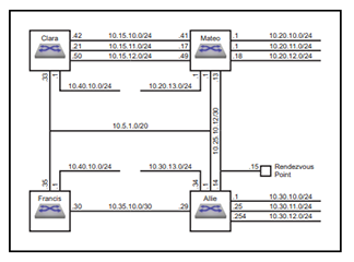
The example multicast network implements these multicast parameters:
Rendezvous Point Address: 10.25.10.15
Switch Clara
- IGMP Snooping: disabled
- Subnet Summary:
- 10.40.10.0/24: vlan 11
- 10.15.10.0/24: vlan 12
- 10.15.11.0/24: vlan 13
- 10.15.12.0/24: vlan 14
- 10.5.1.0/20: vlan 10
Switch Mateo
- IGMP Snooping: disabled
- Subnet Summary:
- 10.20.13.0/24: vlan 18
- 10.20.10.0/24: vlan 15
- 10.20.11.0/24: vlan 16
- 10.20.12.0/24: vlan 17
- 10.15.10.0/24: vlan 12
- 10.15.11.0/24: vlan 13
- 10.15.12.0/24: vlan 14
- 10.25.10.12/30: vlan 19
- 10.5.1.0/20: vlan 10
Switch Allie
- IGMP Snooping: enabled
- Multicast Routing: enabled
- Querier: enabled
- Rendezvous Point Address: 10.25.10.15
- MFIB activity polling interval: 5 second
- Subnet Summary:
- 10.30.13.0/24: vlan 23
- 10.30.10.0/24: vlan 20 PIM-SM enabled
- 10.30.11.0/24: vlan 21 PIM-SM enabled
- 10.30.12.0/24: vlan 22
- 10.25.10.12/30: vlan 19
- 10.35.10.0/30: vlan 24 PIM-SM enabled
- 10.5.1.0/20: vlan 10 PIM-SM enabled
Switch Francis
- IGMP Snooping: enabled
- Multicast Routing: enabled
- Subnet Summary:
- 10.40.10.0/24: vlan 25 PIM-SM enabled
- 10.35.10.0/30: vlan 24 PIM-SM enabled
- 10.5.1.0/20: vlan 10
Example
This example configures PIM-SM.
PIM Commands
PIM Configuration Commands (Global)
- anycast-rp
- candidate
- fast-reroute
- group-expiry-timer
- holdtime
- ip pim dr-notify-delay
- log neighbors
- register local-interface
- router pim bidirectional
- router pim bsr
- router pim sparse-mode
- rp address
- rp allow
- rp candidate
- rp-candidate advertisement-filter
- rp hash algorithm modulo
- sg-expiry-timer
- spt threshold
- ssm range
PIM Configuration Commands (Interface)
PIM Display Commands
anycast-rp
The anycast-rp command configures the switch as a member of an anycast-RP set and establishes a communication link with another member of the set.
When the command is issued in router-multicast ipv4 configuration mode it applies to the default VRF; to use this command in a non-default VRF, issue it in Router-Multicast router-multicast ipv4 configuration mode.
The no anycast-rp and default anycast-rp commands remove the corresponding anycast-rp command from running-config. When the no and default commands do not include a peer address, all commands for the specified RP address are removed.
Command Mode
Router-Multicast IPv4 Configuration
Router-Multicast VRF IPv4 Configuration
Command Syntax
anycast-rp rp_addr peer_addr [REGISTER]
no anycast-rp rp_addr [peer_addr]
default anycast-rp rp_addr [peer_addr]
- rp_addr Rendezvous point IP address (dotted decimal notation).
- peer_addr IP address of another anycast-RP set member (dotted decimal notation). Note, the peer-addr for a local anycast RP must be a /32 address configured under a loopback interface. To enable anycast RP on the router, each RP requires one local peer address. Use the show ip pim anycast-rp [vrf <vrfName>] command to verify the configured local and remote peers.
- REGISTER Number of unacknowledged register messages
the switch sends to the peer router.
- no parameter register count is set to default value of 10.
- register-count r_num where r_num is an integer that ranges from 1 to 4294967295.
- register-count infinity
switch(config)# router pim sparse-mode
switch(config-router-pim-sparse)# ipv4
switch(config-router-pim-sparse-ipv4)# anycast-rp 10.17.255.2 10.1.1.14 register-count 15
switch(config-router-pim-sparse-ipv4)# anycast-rp 10.17.255.2 10.1.2.14 register-count 15
switch(config-router-pim-sparse-ipv4)# anycast-rp 10.17.255.2 10.1.3.14 register-count 15
switch(config-router-pim-sparse-ipv4)# anycast-rp 10.17.255.2 10.1.4.14 register-count 15
switch(config-router-pim-sparse-ipv4)#
candidate
The candidate command configures the switch as a Candidate BSR router (C-BSR). A BSR is a PIM router within the PIM domain through which dynamic RP selection is implemented. The BSR selects RPs from a list of candidate RPs and exchange BootStrap Messages (BSM) with all routers in the domain. The BSR is elected from one of the C-BSRs through an exchange of BSMs.
A subset of PIM routers within the domain are configured as Candidate BootStrap Routers (C-BSRs). Through the exchange of BootStrap Messages (BSMs), the C-BSRs elect the BSR, which then uses BSMs to inform all domain routers of its status.
Command parameters specify the switchs BSR address, the interval between BSM transmissions, the length of the hash mask, and the priority assigned to the switch when electing a BSR.
Entering an candidate command replaces any previously configured candidate command. If the new command does not specify a priority, hash mask length, or interval, the previously configured values persist in running-config.
When the command is issued in the router-pim bsr ipv4 configuration mode it applies to the default VRF; to use this command in a non-default VRF, issue it in router-pim bsr vrf ipv4 configuration mode for the appropriate VRF.
The no candidate and default candidate commands remove the corresponding candidate commands from running-config. The no and default commands restore the priority, hash mask length, and interval parameters to their default values.
Command Mode
Router-PIM BSR IPv4 Configuration
Router-PIM BSR VRF IPv4 Configuration
Command Syntax
candidate INTERFACE [HASHMASK_LENGTH][INTERVAL_PERIOD][PRIORITY_NUM]
no candidate [priority][interval]
default candidate[priority][interval]
- INTERFACE Switch uses IP address of specified
interface as its BSR address. Options include:
- ethernet e_num Ethernet interface specified by e_num.
- loopback l_num Loopback interface specified by l_num.
- management m_num Management interface specified by m_num.
- port-channel p_num Port-Channel Interface specified by p_num.
- vlan v_num VLAN interface specified by v_num.
- HASHMASK_LENGTH Length (in bits) of the hash mask.
- no parameter hash mask remains unchanged from previous setting.
- hashmask 0 - 32 hash mask length (in bits). Default value is 30.
- INTERVAL_PERIOD Period between the transmission of
BSMs (seconds). Default value is 60.
- no parameter interval remains unchanged from previous setting.
- interval 10 - 536870906 transmission interval in seconds.
- PRIORITY_NUM BSR election priority rating. Larger
numbers denote higher priority. Default value is
64.
- no parameter priority remains unchanged from previous setting.
- priority 0 - 255 priority rating.
switch(config)# router pim bsr
switch(config-router-pim-bsr)# ipv4
switch(config-router-pim-bsr-ipv4)# candidate vlan 24 priority 192 interval 30
switch(config-router-pim-bsr-ipv4)#
fast-reroute
The fast-reroute command enables Multicast only Fast Re-Route (MoFRR) to minimize traffic loss in a network when a link or node failure occurs. Traffic loss is minimized by allowing the traffic to flow from the secondary path upon the failure of the primary path.
The no fast-reroute and default fast-reroute commands disable MoFRR by removing the corresponding fast-reroute command from running-config.
Command Mode
Router-PIM BSR IPv4 Configuration
Router-PIM BSR VRF IPv4 Configuration
Command Syntax
fast-reroute acl_name
no fast-reroute acl_name
default fast-reroute acl_name
Parameter
acl_name standard access list name.
Examples- These commands enable fast reroute for ACL
acl2 in the default VRF under the IPv4
configuration.
switch(config)# router pim sparse-mode switch(config-router-pim-sparse)# ipv4 switch(config-router-pim-sparse-ipv4)# fast-reroute acl2 switch(config-router-pim-sparse-ipv4)# - These commands enable fast reroute for ACL
acl2 in vfr red
under the IPv4
configuration.
switch(config)# router pim sparse-mode
switch(config-router-pim-sparse)# vrf red
switch(config-router-pim-sparse-vrf-red)# ipv4
switch(config-router-pim-sparse-vrf-red-ipv4)# fast-reroute acl2
switch(config-router-pim-sparse-vrf-red-ipv4)#
group-expiry-timer
The group-expiry-timer command sets the group-expiry-timer in seconds after which a group with no activity gets deleted from the PIM Rendezvous Point (RP) tree.
When the command is configured in the global configuration mode, the configuration is applied globally on the switch. To apply the configuration only in the bidir-pim mode, the command is configured in the Router-PIM Bidirectional configuration mode. To apply the configuration for a specific VRF, the command is configured in the VRF sub-mode of the Router-PIM Bidirectional configuration mode. Use the pim ipv4 bidirectional command to enter Router-PIM Bidirectional Configuration Mode.
The no group-expiry-timer and default group-expiry-timer applies the system default configuration and removes the corresponding group-expiry-timer command from running-config.
Command Mode
Router-PIM Bidirectional IPv4 Configuration
Router-PIM Bidirectional VRF IPv4 Configuration
Command Syntax
group-expiry-timer value
no group-expiry-timer value
default group-expiry-timer value
Parameter
value specifies the time in seconds after which a group with no activity expires from the PIM RP. Values range from 1 to 210. There is no default value.
Examples- This command configures PIM expiry-timer of 40 seconds
in pim-bidirectional
sub-mode.
switch(config)# router pim bidirectional switch(config-router-pim-bidir)# ipv4 switch(config-router-pim-bidir-ipv4)# group-expiry-timer 40 - This command configures PIM expiry-timer of 120
seconds for vrf
v1.
switch(config)# router pim bidirectional
switch(config-router-pim-bidir)# vrf v1
switch(config-router-pim-bidir-vrf-v1)# ipv4
switch(config-router-pim-bidir-vrf-v1-ipv4)# group-expiry-timer 120
holdtime
The holdtime command specifies the value the switch inserts in the holdtime parameter field in BootStrap Messages (BSM) that it sends. The BSR holdtime defines the timeout period that an elected BSR remains valid after the receipt of a BSM and is also used in dynamic RP configuration. BSR holdtime is designated by the BSR router and communicated to other routers through BSMs.
When the command is issued in router-pim bsr ipv4 configuration mode it applies to the default VRF; to use this command in a non-default VRF, issue it in router-pim bsr vrf ipv4 configuration mode for the appropriate VRF.
The no holdtime and default holdtime commands restore the default holdtime parameter field insertion value of 130 seconds by removing the holdtime statement from running-config.
Command Mode
Router-PIM BSR IPv4 Configuration
Router-PIM BSR VRF IPv4 Configuration
Command Syntax
holdtime period
no holdtime
default holdtime
Parameter
period BSR holdtime (seconds). Value ranges from 12 to 1073741823 (1.073 billion seconds, approximately 34 years). Default is 130.
Exampleswitch(config)# router pim bsr
switch(config-router-pim-bsr)# ipv4
switch(config-router-pim-bsr-ipv4)# holdtime 75
switch(config-router-pim-bsr-ipv4)#ip pim dr-notify-delay
The ip pim dr-notify-delay command sets the designated router (DR) notification delay. This is functionally equivalent to using the dr-notify-delay command within Router-PIM Sparse-mode Configuration Mode. For the command to be most effective, all PIM routers on the LAN segment should have a PIM DR priority value greater than 1. The default delay time is 5 seconds.
The commands no ip pim dr-notify-delay and default ip pim dr-notify-delay remove any previously configured delay time for the Designated Router (DR) notification in PIM.
Command Mode
Global Configuration
Command Syntax
ip pim dr-notify-delay notify_delay_time
no ip pim dr-notify-delay
default ip pim dr-notify-delay
Parameter
notify_delay_time The PIM designated router notify delay time in seconds. Values range from -32767 to 32768.
Guidelines
The notification delay time, which can be configured with a positive or negative value, affects the timing of the Designated Router (DR) election.
In an MLAG configuration:
The delay timer starts shortly after the MLAG reload delay expires. Before this expiration, PIM hello messages are sent with a priority of 1. The timer affects the DR election when a router with the highest DR priority on a LAN segment reloads or when new PIM interfaces are added.
In a non-MLAG configuration:
The notification delay time begins when PIM is initially configured on the interface.
A positive value is required for the timer to influence DR election timing when a router with the highest DR priority on a LAN segment is reloaded or when new PIM interfaces are added.
The configuration of a PIM interface's notify delay time influences the DR priority advertised in PIM hello messages and the device's assumption of DR responsibility.
Positive Notify Delay Time:
- Behavior: The device sends PIM hello messages with a priority of 1 when a new interface comes up or after a device reload, and maintains this priority until the delay time expires.
- DR Responsibility: The device's DR responsibilities continue according to its actual configured DR priority during this time.
- Purpose: Used to avoid multicast packet loss.
- Limitation: May result in a few duplicate packets if multiple PIM routers are forwarding traffic for the same (S, G).
Negative Notify Delay Time:
- Behavior: The device sends PIM hello messages with its configured priority (no modification to the advertised DR priority).
- DR Responsibility: The device will not perform any DR responsibility until the delay time expires.
- Purpose: Used to avoid duplicate packets.
- Limitation: May cause packet loss if no other PIM router is forwarding traffic for an (S, G).
switch(config)# router multicast
switch(config-router-multicast)# ip pim dr-notify-delay 2
ipv4
The ipv4 command places the switch in the IPv4 submode for the PIM configuration mode in which it is entered.
Command Mode
Router Multicast Configuration
Router-PIM Bidirectional Configuration
Router-PIM BSR Configuration
Router-PIM Sparse-mode Configuration
Command Syntax
ipv4
Examples- These commands place the switch in the router multicast ipv4
configuration
mode.
switch(config)# router multicast switch(config-router-multicast)# ipv4 switch(config-router-multicast-ipv4)# - These commands place the switch in the router-pim bidirectional
ipv4 configuration
mode.
switch(config)# router pim bidirectional switch(config-router-pim-bidir)# ipv4 switch(config-router-pim-bidir-ipv4)# - These commands place the switch in the router-pim bsr ipv4
configuration
mode.
switch(config)# router pim bsr switch(config-router-pim-bsr)# ipv4 switch(config-router-pim-bsr-ipv4)# - These commands place the switch in the router-pim sparse-mode ipv4
configuration
mode.
switch(config)# router pim sparse-mode
switch(config-router-pim-sparse)# ipv4
switch(config-router-pim-sparse-ipv4)#
log neighbors
The log neighbors command configures the switch to generate a log message when a neighbor entry is added or removed from the PIM Neighbor table. This function is enabled by default.
The no log neighbors command disables log message generation based on changes to the PIM Neighbor table; this command is stored in the running-config. The log neighbors and default log neighbors commands restore the default setting of generating log messages by deleting the no log neighbors statement from running-config.
Command Mode
Router-PIM Sparse-mode IPv4 Configuration
Router-PIM Sparse-mode VRF IPv4 Configuration
Router-PIM Bidirectional IPv4 Configuration
Router-PIM Bidirectional VRF IPv4 Configuration
Command Syntax
log neighbors
no log neighbors
default log neighbors
Examples- These commands configure the switch to stop generating log messages based on PIM
Neighbor table changes in the default
VRF.
switch(config)# router pim sparse-mode switch(config-router-pim-sparse)# ipv4 switch(config-router-pim-sparse-ipv4)# no log neighbors switch(config-router-pim-sparse-ipv4)# - These commands configure the switch to generate log messages when a neighbor
entry is added or removed from the PIM Neighbor table in the default
VRF.
switch(config)# router pim sparse-mode
switch(config-router-pim-sparse)# ipv4
switch(config-router-pim-sparse-ipv4)# log neighbors
switch(config-router-pim-sparse-ipv4)#
pim bsr ipv4 border
The pim bsr ipv4 border command prevents the switch from sending BootStrap router Messages (BSMs) over the configuration mode interface. By default, BSMs are transmitted over all PIM-enabled interfaces.
The no pim bsr ipv4 border and default pim bsr ipv4 border commands restore the transmission of BSMs over the configuration mode interface by removing the corresponding pim bsr ipv4 border statement from running-config.
Command Mode
Interface-Ethernet Configuration
Interface-Port-Channel Configuration
Interface-VLAN Configuration
Command Syntax
pim bsr ipv4 border
no pim bsr ipv4 border
default pim bsr ipv4 border
Exampleswitch(config)# interface vlan 10
switch(config-if-Vl10)# pim bsr ipv4 border
switch(config-if-Vl10)#pim ipv4 bidirectional
The pim ipv4 bidirectional command enables PIM bidirectional and IGMP (router mode) on the configuration mode interface.
The no pim ipv4 bidirectional, no pim ipv4, default pim ipv4 bidirectional, and default pim ipv4 commands restore the default PIM and IGMP (router mode) settings of disabled on the configuration mode interface by removing the pim ipv4 bidirectional statement from running-config.
Command Mode
Interface-Ethernet Configuration
Interface-Port-Channel Configuration
Interface-VLAN Configuration
Command Syntax
pim ipv4 bidirectional
no pim ipv4
no pim ipv4 bidirectional
default pim ipv4
default pim ipv4 bidirectional
Exampleswitch(config)# interface vlan 4
switch(config-if-Vl4)# pim ipv4 bidirectional
switch(config-if-Vl4)#pim ipv4 border-router
The pim ipv4 border-router command configures the configuration mode interface as a PIM Multicast Border Router (MBR). A PIM MBR interface allows multicast traffic from sources that are outside of the PIM domain.
This command does not control the transmission or reception of PIM protocol packets by the interface.
Sources learned through an MBR interface are treated as local sources (directly connected to the switch). The border-bit is set in all PIM register messages sent for these sources.
The no pim ipv4 border-router and default pim ipv4 border-router commands removes the PIM MBR configuration for the configuration mode interface by removing the corresponding pim ipv4 border-router statement from running-config.
Command Mode
Interface-Ethernet Configuration
Interface-Port-Channel Configuration
Interface-VLAN Configuration
Command Syntax
pim ipv4 border-router
no pim ipv4 border-router
default pim ipv4 border-router
Exampleswitch(config)# interface vlan 200
switch(config-if-VL200)# ip address 10.44.2.1/24
switch(config-if-VL200)# no pim ipv4 sparse-mode
switch(config-if-VL200)# pim ipv4 border-router
switch(config-if-VL200)# show active
interface Vlan200
ip address 10.44.2.1/24
pim ipv4 border-router
switch(config-if-VL200)#exit
switch(config)# show ip pim interface
AddressInterfaceModeNeighborHello DRDR
AddressPktsQedPktsDropped
CountIntvl Pri
10.44.2.1Vlan200mbr030110.44.2.100
switch(config)#pim ipv4 dr-priority
- If at least one router does not advertise a DR priority value, then PIM-SM elects the router with the highest IP address as the DR.
- If all routers advertise a DR priority value, then PIM-SM elects the router with the highest DR priority value as the DR.
The pim ipv4 dr-priority command sets the DR priority value that the configuration mode interface advertises. By default, the interface does not advertise a DR priority value.
The no pim ipv4 dr-priority and default pim ipv4 dr-priority commands force the use of IP addresses to elect the designated router by removing the corresponding pim ipv4 dr-priority statement from running-config.
Command Mode
Interface-Ethernet Configuration
Interface-Port-Channel Configuration
Interface-VLAN Configuration
Command Syntax
pim ipv4 dr-priority level
no pim ipv4 dr-priority [level]
default pim ipv4 dr-priority [level]
Parameter
level DR selection priority rating. Value ranges from 0 to 4294967295.
Examples- This command configures the dr-priority value of 15 on
interface vlan
4.
switch(config)# interface vlan 4 switch(config-if-Vl4)# pim ipv4 dr-priority 15 switch(config-if-Vl4)# - This command force the use of IP addresses to elect the designated
router.
switch(config-if-Vl4)# no pim ipv4 dr-priority
switch(config-if-Vl4)#
pim ipv4 hello count
The pim ipv4 hello count command sets the PIM hello count for the interface being configured. PIM hold time is calculated by multiplying the configured hello interval by the hello count, ensuring that the PIM neighbor stays up for the specified time after which the neighbor expires.
The no pim ipv4 hello count command removes the corresponding pim ipv4 hello count command from running-config.
Command Mode
Interface-Ethernet Configuration
Interface-Port-Channel Configuration
Interface-VLAN Configuration
Command Syntax
pim ipv4 hello count [multiple]
no pim ipv4 hello count [multiple]
Parameter
multiple hello count multiplier. Value ranges from 1.5 to 65535. The hello hold time is the configured hello interval multiplied by the hello count.
Examples- This command configures a hold time interval of
225 seconds on
interface vlan2925 by
multiplying the default 30-second
hello interval by a hello count of
7.5.
switch(config)# interface vlan2925 switch(config-if-Vl2925)# pim ipv4 hello count 7.5 switch(config-if-Vl2925)# - This show command displays the hold time and other configuration
details on interface
vlan2925.
switch# show ip pim interface vlan2925 details
Interface Vlan2925 address is 1.0.1.1
Vif number is 0
PIM: enabled
PIM version: 2, mode: sparse
PIM neighbor count: 0
PIM Effective DR: 1.0.1.1 (this system)
PIM Effective DR Priority: 1
PIM Effective Propagation Delay: 500 milliseconds
PIM Effective Override Interval: 2500 milliseconds
PIM Effective Tracking Support: disabled
PIM Hello Interval: 30 seconds
PIM Hello Hold Time: 225 seconds <====== New Hold Time (= 7.5 * 30)
PIM Hello Priority: 1 seconds
PIM Hello Lan Delay: 500 milliseconds
PIM Assert Override Interval: 3 seconds
mrtr1#
pim ipv4 hello interval
The pim ipv4 hello interval command specifies the transmission interval between PIM hello messages originating from the configuration mode interface.
The no pim ipv4 hello interval and default pim ipv4 hello interval commands restore the default query interval of 30 seconds for the configuratiom mode interface by removing the corresponding pim ipv4 hello interval command from running-config.
Command Mode
Interface-Ethernet Configuration
Interface-Port-Channel Configuration
Interface-VLAN Configuration
Command Syntax
pim ipv4 hello interval period
no pim ipv4 hello interval [period]
default pim ipv4 hello interval [period]
Parameter
period query interval (seconds). Value ranges from 1 to 1000000 (1 million). Default is 30.
Exampleswitch(config)# interface vlan 4
switch(config-if-Vl4)# pim ipv4 hello interval 45
switch(config-if-Vl4)#pim ipv4 join-prune count
The pim ipv4 join-prune count command configures the number of times a join or prune messages can be missed before the upstream neighbor time expires.
The join-prune interval multiplied by the count is considered as join or prune hold time (specified in seconds), which is used in the join or prune messages. It is recommended to use the default configuration for pim ipv4 join-prune interval, and modify the pim ipv4 join-prune count to increase the join or prune holdtime. Increasing the join-prune hold time delays the deletion of an S,G route on the upstream neighbor when join-prune messages are not sent to the neighbor. The maximum possible value for join or prune hold-time is 65535.
The no pim ipv4 join-prune count and default pim ipv4 join-prune count commands restore the default join or prune count for the configuration mode interface by removing the corresponding pim ipv4 join-prune count command from running-config.
Command Mode
Interface-Ethernet Configuration
Interface-VLAN Configuration
Command Syntax
pim ipv4 join-prune count count_value
no pim ipv4 join-prune count count_value
default pim ipv4 join-prune count count_value
Parameter
count_value The number of missed join or prune after which the route expires. Value ranges from 1.5 to 65535.
Exampleswitch(config)# interface Ethernet 1/1
switch(config-if-Et1/1)# pim ipv4 join-prune count 5
switch(config-if-Et1/1)#pim ipv4 join-prune interval
The pim ipv4 join-prune interval command specifies the period between join or prune messages that the configuration mode interface originates and sends to the upstream RPF neighbor.
The no pim ipv4 join-prune interval and default pim ipv4 join-prune interval commands restores the default join or prune interval to 60 seconds for the configuration mode interface by removing the corresponding pim ipv4 join-prune interval command from running-config.
Command Mode
Interface-Ethernet Configuration
Interface-Port-Channel Configuration
Interface-VLAN Configuration
Command Syntax
pim ipv4 join-prune interval [period]
no pim ipv4 join-prune interval [period]
default pim ipv4 join-prune interval [period]
Parameter
period join or prune interval (seconds). Value ranges from 1 to 18724. Default is 60.
Exampleswitch(config)# interface vlan 4
switch(config-if-Vl4)# pim ipv4 join-prune interval 75
switch(config-if-Vl4)#pim ipv4 neighbor-filter
The pim ipv4 neighbor-filter command configures the configuration mode interface to filter PIM control packets on the basis of neighbor addresses listed in a specified standard access list.
The no pim ipv4 neighbor-filter and default pim ipv4 neighbor-filter commands disable the configuration mode interface from filtering PIM control packets by removing the corresponding ip pim ipv4 neighbor-filter command from running-config.
Command Mode
Interface-Ethernet Configuration
Interface-Port-Channel Configuration
Interface-VLAN Configuration
Command Syntax
pim ipv4 neighbor-filter access_list
no pim ipv4 neighbor-filter
default pim ipv4 neighbor-filter
Parameter
access_list name of the standard IP access list.
Exampleswitch(config)# ip access-list standard filter_1
switch(config-std-acl-filter_1)# permit 10.13.24.9/24
switch(config-std-acl-filter_1)# exit
switch(config)# interface vlan 4
switch(config-if-Vl4)# pim ipv4 neighbor-filter filter_1
switch(config-if-Vl4)#pim ipv4 sparse-mode
The pim ipv4 sparse-mode command enables PIM IPv4 Sparse Mode (PIM-SM) and IGMP (router mode) on the configuration mode interface.
The no pim ipv4 sparse-mode, no pim ipv4, default pim ipv4 sparse-mode, and default pim ipv4 commands restore the default PIM and IGMP (router mode) settings of disabled on the configuration mode interface by removing the pim ipv4 sparse-mode statement from running-config.
Command Mode
Interface-Ethernet Configuration
Interface-Port-Channel Configuration
Interface-VLAN Configuration
Command Syntax
pim ipv4 sparse-mode
no pim ipv4
no pim ipv4 sparse-mode
default pim ipv4
default pim ipv4 sparse-mode
Exampleswitch(config)# interface vlan 4
switch(config-if-Vl4)# pim ipv4 sparse-mode
switch(config-if-Vl4)#pim ipv6 sparse-mode
The pim ipv6 sparse-mode command enables PIM IPv6 Sparse Mode (PIM-SM) on the configuration mode interface.
The no pim ipv6 sparse-mode, no pim ipv6, default pim ipv6 sparse-mode, and default pim ipv6 commands restore the default PIM settings of disabled on the configuration mode interface by removing the pim ipv6 sparse-mode command from the running-config.
Command Mode
Interface-Ethernet Configuration
Interface-Port-Channel Configuration
Interface-VLAN Configuration
Command Syntax
pim ipv6 sparse-mode
no pim ipv6
no pim ipv6 sparse-mode
default pim ipv6
default pim ipv6 sparse-mode
Exampleswitch(config)# interface vlan 8
switch(config-if-Vl8)# pim ipv6 sparse-mode
switch(config-if-Vl8)#register checksum
The register checksum command in the Router PIM Sparse-Mode IPv6 Configuration Mode configures a checksum to use for PIM IPv6 register messages. The no | default versions of the command restores the default method of filling the register packet source field by removing the statement from the running-config.
Command Mode
Router PIM Sparse-Mode IPv6 Configuration Mode
Command Syntax
register checksum [full | header]
Parameters
- full - Compute the checksum on the entire register message.
- header - Compute the checksum on the first eight (8) bytes of the register message.
Example
switch(config)# router pim sparse-mode
           switch(config-router-pim-sparse)# ipv6
               switch(config-router-pim-sparse-ipv6)# register checksum full
register local-interface
The register local-interface command programs the switch to fill the source field in all outbound PIM SM register packets with the IP address of a specified interface or the incoming interface of the group specified by the message. By default, the source field is filled with the IP address from the interface associated with the best route to the RP.
When the command is issued in Router-PIM Sparse-mode IPv4 ConfigurationMode, it applies to the default VRF; to use this command in a non-default VRF, issue it in Router-PIM Sparse-mode VRF IPv4 Configuration.
The no register local-interface and default register local-interface commands restore the default method of filling the register packet source field by removing the ip register local-interface statement from running-config.
Command Mode
Router-PIM Sparse-mode IPv4 Configuration
Router-PIM Sparse-mode VRF IPv4 Configuration
Command Syntax
register local-interface INT_NAME
no register local-interface
default register local-interface
Parameters
- ethernet e_num Ethernet interface specified by e_num.
- loopback l_num Loopback interface specified by l_num.
- management m_num Management interface specified by m_num.
- port-channel p_num Port channel interface specified by p_num.
- vlan v_num VLAN interface specified by v_num.
switch(config)# router pim sparse-mode
switch(config-router-pim-sparse)# ipv4
switch(config-router-pim-sparse-ipv4)# register local-interface loopback 2
switch(config-router-pim-sparse-ipv4)#
router pim bidirectional
The router pim bidirectional command places the switch in the router-pimbidirectional configuration mode.
Command Mode
Global Configuration
Command Syntax
router pim bidirectional
Exampleswitch(config)# router pim bidirectional
switch(config-router-pim-bidir)#router pim bsr
The router pim bsr command places the switch in the router-pim bsr configuration mode.
Command Mode
Global Configuration
Command Syntax
router pim bsr
Exampleswitch(config)# router pim bsr
switch(config-router-pim-bsr)#router pim sparse-mode
The router pim sparse-mode command places the switch in the router-pim sparse-mode configuration mode.
Command Mode
Global Configuration
Command Syntax
router pim sparse-mode
Exampleswitch(config)# router pim sparse-mode
switch(config-router-pim-sparse)#rp address
The rp address command configures the address of a Protocol Independent Multicast (PIM) static Rendezvous Point (RP) for a specified multicast subnet. If the command does not specify a subnet, the static RP maps to all multicast groups (224/4). Dynamic RPs override static RPs unless the static RP is given priority by using the override option of this command.
Multicast groups use RPs to connect sources and receivers. A PIM domain requires that all routers have consistently configured RP addresses.
- Different size subnets: group uses command with the largest subnet.
- Same size subnets: group uses command as determined by hash algorithm.
When the command is issued in the router-multicast configuration mode it applies to the default VRF; to use this command in a non-default VRF, issue it in the router-multicast vrf configuration mode.
The no rp address and default rp address commands remove the corresponding rp address command from running-config.
Command Mode
Router-PIM Sparse-mode IPv4 Configuration
Router-PIM Sparse-mode VRF IPv4 Configuration
Command Syntax
rp address rp_addr [MULTICAST_SUBNET][HASHMASK_LENGTH][BSR_OVERRIDE][PRIORITY_NUM]
no rp address rp_addr [MULTICAST_SUBNET]
default rp address rp_addr [MULTICAST_SUBNET]
- rp_addr Rendezvous point IP address (dotted decimal notation).
- MULTICAST_SUBNET Multicast IP address space (CIDR or
address-mask).
- no parameter Default multicast group IP address of 224/4.
- gp_addr Multicast group IP address (CIDR or address-mask).
- access-list acl_name Standard access control list that specifies the multicast group address.
- acl_name Standard access control list that specifies the multicast group address.
- HASHMASK_LENGTH Length (in bits) of the hash mask.
- no parameter hash mask remains unchanged from previous setting.
- hashmask 0 - 32 hash mask length (in bits). Default value is 30.
- BSR_OVERRIDE Configures priority relative to dynamic
RPs selected by BSR.
- no parameter Dynamic RPs have priority over specified RP.
- override RP has priority over dynamic RPs.
- PRIORITY_NUM BSR election priority rating. Larger
numbers denote higher priority. Default value is 0.
- no parameter priority remains unchanged from previous setting.
- priority 0 - 255 priority rating.
switch(config)# router pim sparse-mode
switch(config-router-pim-sparse)# ipv4
switch(config-router-pim-sparse-ipv4)# rp address 10.17.255.2
switch(config-router-pim-sparse-ipv4)#rp allow
The rp allow command accepts and allows PIM (*,G) join message with an RP address that is different from the configured RPs for that particular (*,G).
The no rp allow and default rp allow commands disable this behavior by removing the corresponding rp allowcommand from running-config.
Command Mode
Router-PIM Sparse-mode IPv4 Configuration
Router-PIM Sparse-mode VRF IPv4 Configuration
Command Syntax
rp allow
no rp allow
default rp allow
Examples- These commands configure the switch to accept PIM (*,G) join messages in the
default VRF that include RP addresses not configured on the switch for that
(*,G)
route.
switch(config-router-pim-sparse)# ipv4 switch(config-router-pim-sparse-ipv4)# rp allow - These commands configure the switch to accept PIM (*,G) join messages in VRF
blue that include RP addresses not configured on the switch for that (*,G)
route.
switch(config-router-pim-sparse)# vrf blue switch(config-router-pim-sparse-vrf-blue)# ipv4 switch(config-router-pim-sparse-vrf-blue-ipv4)# rp allow
rp candidate
The rp candidate command configures the switch as a Candidate Rendezvous Point (C-RP). The BSR selects a multicast groups dynamic RP set from the list of C-RPs in the PIM domain. The command specifies the interface (used to derive the RP address), C-RP advertisement interval, and priority rating. The BSR selects the RP set by comparing C-RP priority ratings. The C-RP advertisement interval specifies the period between successive C-RP advertisement message transmissions to the BSR.
Running-config supports multiple multicast groups through multiple rp candidate statements:
- All commands must specify the same interface. Issuing a command with an interface that differs from existing commands removes all existing commands from running-config.
- The running-config stores the interval setting in a separate statement that applies to all rp candidate statements. When a command specifies an interval that differs from the previously configured value, the new value replaces the old value and applies to all configured rp candidate statements. The default interval value is 60 seconds.
When the command is issued in Router-Multicast Configuration Mode it applies to the default VRF; to use this command in a non-default VRF, issue it in the router-multicast vrf configuration mode.
The no rp candidate and default rp candidate commands remove rp candidate from running-config for the specified group. When these commands do not specify a multicast group, all rp candidate statements are removed from running-config.
The no rp candidate interval and default rp candidate interval commands restore the interval setting to the default value of 60 seconds. The no rp candidate priority and default rp candidate priority commands restore the priority setting to the default value of 192.
Command Mode
Router-PIM Sparse-mode IPv4 Configuration
Router-PIM Sparse-mode VRF IPv4 Configuration
Router-PIM Bidirectional IPv4 Configuration
Router-PIM Bidirectional VRF IPv4 Configuration
Command Syntax
rp candidate INTERFACE [GROUP_ADDR][PRIORITY_NUM][INTERVAL_PERIOD]
no rp candidate [INTERFACE][GROUP_ADDR]
no rp candidate [INTERFACE] interval
no rp candidate [INTERFACE] priority
default rp candidate [INTERFACE][GROUP_ADDR]
default rp candidate [INTERFACE] interval
default rp candidate [INTERFACE] priority
- INTERFACE Switch uses IP address of specified
interface as its C-RP address. Options include:
- ethernet e_num Ethernet interface specified by e_num.
- loopback l_num Loopback interface specified by l_num.
- management m_num Management interface specified by m_num.
- port-channel p_num Port-Channel Interface specified by p_num.
- vlan v_num VLAN interface specified by v_num.
- VXLAN vx_num VXLAN interface specified by vx_num.
- GROUP_ADDR address of multicast group for which
candidate is configured. Options include:
- no parameter default multicast group (224.0.0.0/4).
- net_addr multicast IPv4 subnet address (CIDR or address mask).
- access-list acl_name standard access control list that specifies the multicast group address.
- PRIORITY_NUM RP selection priority rating. Smaller
numbers denote higher priority.
- no parameter priority rating is set to the default value of 192.
- priority 0 - 255 priority rating.
- INTERVAL_PERIOD Period between consecutive
RP-advertisement message transmissions (seconds). Value also applies to
previously configured rp candidate statements.
- no parameter interval remains unchanged from previous setting.
- interval 10 - 16383 transmission interval.
switch(config)# router pim sparse-mode
switch(config-router-pim-sparse)# ipv4
switch(config-router-pim-sparse-ipv4)# rp candidate vlan 24 235.1.1.0/24 priority 48 interval 45
switch(config-router-pim-sparse-ipv4)#rp hash algorithm modulo
The rp hash algorithm modulo command configures the load-balancing scheme across available Rendezvous Points (RP).
The configuration results in a round robin-based load balancing across available RPs, achieved by module operation of the destination group address with the number of RPs available.
The no rp hash algorithm modulo and default rp hash algorithm modulo commands result in the default load-balancing scheme which is to use a hash function to get a group-RP mapping.
Command Mode
Router-PIM Sparse-mode IPv4 Configuration
Router-PIM Sparse-mode VRF IPv4 Configuration
Router-PIM Sparse-mode IPv6 Configuration
Router-PIM Sparse-mode VRF IPv6 Configuration
Router-PIM Bidirectional VRF IPv4 Configuration
Command Syntax
rp hash algorithm modulo
no rp hash algorithm modulo
default rp hash algorithm modulo
Examples- These commands configures the hash algorithm module for a VRF named
blue in the router-pim sparse-mode
ipv4 configuration mode.
switch(config)# router pim sparse-mode switch(config-router-pim-sparse)# ipv4 switch(config-router-pim-sparse-ipv4)# vrf red switch(config-router-pim-sparse-vrf-red-ipv4)# rp hash algorithm modulo - These commands configures the hash algorithm module for a VRF named
blue in the router-pim
bidirectional-mode vrf ipv4 configuration mode.
switch(config)# router pim bidirectional switch(config-router-pim-bidir)# ipv4 switch(config-router-pim-bidir-ipv4)# vrf red switch(config-router-pim-bidir-vrf-red-ipv4)# rp hash algorithm modulo
rp-candidate advertisement-filter
The rp-candidate advertisement-filter command filters the RP candidate advertisements from certain IP addresses. When rp-candidate advertisement-filter command is configured, PIM BSR filters RP candidate messages from ip-addresses matching the prefix list from the access-list that is configured.
The no rp-candidate advertisement-filter and default rp-candidate advertisement-filter commands removes rp-candidate advertisement-filter from running-config for the specified group.
Command Mode
Router-PIM BSR IPv4 Configuration
Router-PIM BSR VRF IPv4 Configuration
Command Syntax
rp-candidate advertisement-filter access-list access-list_name
no rp-candidate advertisement-filter access-list access-list_name
default rp-candidate advertisement-filter access-list access-list_name
Parameter
access-list_name Standard access control list that specifies the multicast group address.
Exampleswitch(config-router-pim-bsr)# ipv4
switch(config-router-pim-bsr-ipv4)# rp-candidate advertisement-filter access-list test1
switch(config-router-pim-bsr-vrf-red-ipv4)# rp-candidate advertisement-filter access-list test2sg-expiry-timer
The sg-expiry-timer command configures the (S, G) expiry timer interval for PIM-SM (S, G) multicast routes. The command does not apply to (*, G) mroutes.
When the command is issued in the router-multicast configuration mode it applies to the default VRF; to use this command in a non-default VRF, issue it in the router-multicast vrf configuration mode.
The no sg-expiry-timer and default sg-expiry-timer commands restore the default setting of 210 seconds by removing the sg-expiry-timer statement from running-config.
Command Mode
Router-PIM Sparse-mode IPv4 Configuration
Router-PIM Sparse-mode VRF IPv4 Configuration
Command Syntax
sg-expiry-timer period
no sg-expiry-timer
default sg-expiry-timer
Parameter
period expiry timer interval (seconds). Value ranges from 120 to 65535 seconds. The default value is 210 seconds.
Exampleswitch(config)# router pim sparse-mode
switch(config-router-pim-sparse)# ipv4
switch(config-router-pim-sparse-ipv4)# sg-expiry-timer 150
switch(config-router-pim-sparse-ipv4)#show ip pim bsr
The show ip pim bsr command displays the switchs BootStrap Router (BSR) information.
Command Mode
EXEC
Command Syntax
show ip pim bsr [GROUP_FILTER]
Parameters
- no parameter Displays data for all groups.
- net_addr Displays message for specified group address. (CIDR or address mask).
switch> show ip pim bsr
PIMv2 Bootstrap information
This system is the Bootstrap Router (BSR)
BSR address: 10.1.1.1
Uptime: 00:14:42, BSR Priority: 0, Hash mask length: 30
Next bootstrap message in 00:00:05show ip pim config-sanity
The show ip pim config-sanity command displays diagnostic information about the switch's PIM configuration.
Command Mode
EXEC
Command Syntax
show ip pim config-sanity
Exampleswitch> show ip pim config-sanity
DISCLAIMER: Below are only hints of potential PIM misconfiguration.
They do not necessary imply that there is a real problem.
The interfaces with PIM which are down: Vl4
switch>show ip pim interface
The show ip pim interface command displays information about interfaces configured for PIM.
Command Mode
EXEC
Command Syntax
show ip pim interface [INT_NAME][INFO_LEVEL]
- INT_NAME Interface type and number. Values
include:
- no parameter displays information for all interfaces.
- ethernet e_num Ethernet interface specified by e_num.
- port-channel p_num Port-Channel Interface specified by p_num.
- vlan v_num VLAN interface specified by v_num.
- VXLAN vx_num VXLAN interface specified by vx_num.
- INFO_LEVEL specifies level of information
detail provided by the command.
- no parameter table of basic configuration information.
- detail list of complete configuration information.
- This command displays information about all interfaces on which PIM is
enabled.
switch> show ip pim interface Address InterfaceModeNeighbor Hello DR DR Address PktsQed PktsDropped Count Intvl Pri 10.17.254.30 Vlan3910 sparse1 30 1 10.17.254.30 0 0 10.17.254.162 Vlan3925 sparse2 30 1 10.17.254.163 0 0 10.17.254.106 Vlan3912 sparse1 30 1 10.17.254.106 0 0 10.17.254.137 Ethernet12 sparse1 30 1 10.17.254.138 0 0 switch> - This command displays detailed PIM information for interface vlan
26.
switch> show ip pim interface vlan 26 detail Interface address is 172.17.26.1 Vif number is 1 PIM: enabled PIM version: 2, mode: sparse PIM DR: 172.17.26.1 (this system) PIM DR Priority: 1 PIM neighbor count: 0 PIM Hello Interval: 30 seconds PIM Hello Priority: 1 PIM Hello Lan Delay: 500 milliseconds PIM Hello Override Interval: 2500 milliseconds PIM Hello Lan Prune Delay in use PIM Hello Generation ID: 0x4a05aa0 PIM Hello Generation ID is not required PIM Triggered Hello Delay: 5 seconds PIM Join-Prune Interval: 60 seconds PIM State-Refresh processing: disabled PIM State-Refresh Interval: unknown seconds PIM Graft Retry Interval: unknown seconds PIM domain border: disabled switch>
show ip pim neighbor
The show ip pim neighbor command displays information about Protocol Independent Multicast (PIM) neighbors discovered by hello messages.
Command Mode
EXEC
Command Syntax
show ip pim neighbor [INT_NAME][BFD_DATA]
- INT_NAME Interface type and number. Values
include:
- no parameter displays information for all interfaces.
- ethernet e_num Ethernet interface specified by e_num.
- loopback l_num Loopback interface specified by l_num.
- management m_num Management interface specified by m_num.
- port-channel p_num Port-Channel Interface specified by p_num.
- vlan v_num VLAN interface specified by v_num.
- VXLAN vx_num VXLAN interface specified by vx_num.
- BFD_DATA Specifies inclusion of BFD data.
- no parameter BFD data is not displayed.
- bfd BFD data is displayed.
- This command displays information about neighbor PIM
routers.
switch> show ip pim neighbor PIM Neighbor Table Neighbor Address Interface Uptime Expires Mode 10.17.255.2 Vlan2028 21d22h 00:01:31 sparse switch> - This command displays information about neighbor PIM routers and the status of
BFD.
switch> show ip pim neighbor bfd PIM Neighbor Table Flags: U - BFD is enabled and is UP I - BFD is enabled and is INIT D - BFD is enabled and is DOWN N - Not running BFD Neighbor Address Interface Uptime Expires ModeFlags 10.17.255.2 Vlan2028 21d22h 00:01:31 sparseU switch>
show ip pim protocol counters
The show ip pim protocol command displays statistics about Protocol Independent Multicast (PIM) control messages sent and received by the switch.
Command Mode
EXEC
Command Syntax
show ip pim protocol counters [INT_NAME]
Parameters
- no parameter displays information for all interfaces.
- ethernet e_num Ethernet interface specified by e_num.
- loopback l_num Loopback interface specified by l_num.
- management m_num Management interface specified by m_num.
- port-channel p_num Port-Channel Interface specified by p_num.
- vlan v_num VLAN interface specified by v_num.
- VXLAN vx_num VXLAN interface specified by vx_num.
switch> show ip pim protocol counters
PIM Control Counters
Received Sent Invalid
Assert 0 37 0
Bootstrap Router 0 0 0
CRP Advertisement 0 0 0
Graft 0 0 0
Graft Ack 0 0 0
Hello 63168 126355 0
J/P 275714 143958 0
Join 0 0 0
Prune 0 0 0
Register 0 13643 0
Register Stop 11839 0 0
State Refresh 0 0 0show ip pim register-source
The show ip pim register-source command displays the name of the interface from where the switch derives the IP address that it uses to fill the source field in all outbound PIM SM register packets. The register local-interface command specifies this interface.
By default, the source field is filled with the IP address from the interface associated with the best route to the RP. The show ip pim register-source command does not return a value when the source field is filled with the default value.
Command Mode
EXEC
Command Syntax
show ip pim register-source
Exampleswitch> show ip pim register-source
Ethernet22show ip pim rp
The show ip pim rp command displays the status and multicast group of each cached Rendezvous Point (RP).
Command Mode
EXEC
Command Syntax
show ip pim rp
Exampleswitch> show ip pim rp
show ip pim rp
The PIM RP Set
Group: 224.0.0.0/4
RP: 10.1.2.3
Uptime: 00:05:12, Expires: never, Priority: 1 Override: 1show ip pim rp-candidate
The show ip pim rp-candidate command displays the Rendezvous Point (RP) that is used for a specified multicast group.
Command Mode
EXEC
Command Syntax
show ip pim rp-candidate
Exampleswitch> show ip pim rp-candidate
Candidate RP information
Candidate RP Address: 10.0.12.2
CRP Holdtime: 150 seconds
Group 224.2.0.0/16 Priority 2show ip pim rp-hash
The show ip pim rp-hash displays the group to RP-hash mapping for the specified group and the list of qualifying candidate RPs.
Command Mode
EXEC
Command Syntax
show ip pim rp-hash ipv4_addr [INFO_LEVEL]
- ipv4_addr multicast group IPv4 address.
- INFO_LEVEL specifies level of information detail
provided by the command.
- no parameter RP-hash map and list of candidate RPs.
- detail includes data about the selected RP.
switch> show ip pim rp-hash 224.1.0.0
RP 10.1.2.3show ip pim upstream joins
The show ip pim upstream joins command displays the join messages that the switch is scheduled to send.
Command Mode
EXEC
Command Syntax
show ip pim upstream joins [JOIN_ADDRESSES] [NEIGHBOR_FILTER]
- JOIN_ADDRESSES Filters messages by source and group
addresses.
- no parameter displays all join messages.
- source_addr displays all join messages for specified source group IPv4 address.
- group_addr displays all join messages for specified multicast IPv4 address.
- source_addr group_addr displays join message with specified source and group addresses.
- group_addr
source_addr displays join message with specified group and
source addresses.
group_addr must be a valid multicast IPv4 address.
- NEIGHBOR_FILTER specifies neighbors for which command provides
data.
- no parameter Displays messages for all neighbors.
- neighbor neighbor_addr Displays message for specified neighbor address.
switch> show ip pim upstream joins
------------- show ip pim upstream joins -------------
Neighbor address: 10.1.1.1
Via interface: 10.1.1.2
Next message in 1 seconds
Group: 10.10.10.3
Joins:
10.25.1.1/32 SPT
Prunes:
No prunes included
Neighbor address: 10.1.1.6
Via interface: 10.1.1.5
Next message in 1 seconds
Group: 10.14.1.69
Joins:
10.105.14.3/32 SPT
Prunes:
No prunes included
switch>spt threshold
- When running-config does not list this command, the switch joins the SPT immediately after receiving the first PIM packet from a new source. The switch joins the SPT by sending PIM join message toward the source.
- When running-config lists this command with a value of infinity, the switch never joins the SPT.
The no spt threshold and default spt threshold commands remove the corresponding spt threshold command from running-config.
Command Mode
Router-PIM Sparse-mode IPv4 Configuration
Router-PIM Sparse-mode VRF IPv4 Configuration
Command Syntax
spt threshold {0 | infinity}[match list acl_name]
no spt threshold {0 | infinity}[match list acl_name]
default spt threshold{0 | infinity} [match list acl_name]
- 0 The switch immediately joins the SPT. This is the default value.
- infinity The switch never joins the SPT.
- acl_name name of access control list. If no ACL is supplied, the configuration is applied to all multicast groups within the VRF which are not configured by an ACL.
switch(config)# router pim sparse-mode
switch(config-router-pim-sparse)# ipv4
switch(config-router-pim-sparse-ipv4)# spt threshold 0 match list group-1
switch(config-router-pim-sparse-ipv4)#ssm range
The ssm range command defines the Source Specific Multicast (SSM) range of IP multicast addresses.
SSM is a multicast packet delivery method where only packets originating from a specific source address requested by a receiver are routed to that receiver. SSM explicitly excludes the use of (*,G) join for applicable multicast groups. Source-specific multicast differs from Any-Source Multicast (ASM), where a receiver expresses interest in traffic to a multicast address, then receives traffic from all multicast sources sending to that address.
When the command is issued in the router-pim sparse-mode ipv4 configuration mode it applies to the default VRF; to use this command in a non-default VRF, issue it in the router-pim sparse-mode vrf ipv4 configuration mode.
The no ssm range and default ssm range commands remove the SSM IP multicast address range by deleting the ssm range statement from running-config.
Command Mode
Router-PIM Sparse-mode IPv4 Configuration
Router-PIM Sparse-mode VRF IPv4 Configuration
Command Syntax
ssm range {acl_name | standard}
no ssm range
default ssm range
- acl_name sets the SSM range to address set specified by the standard ACL.
- standard sets the SSM range to 232/8.
- These commands configure the SSM address range to
232/8 in the default
VRF.
switch(config)# router pim sparse-mode switch(config-router-pim-sparse)# ipv4 switch(config-router-pim-sparse-ipv4)# ssm range standard switch(config-router-pim-sparse-ipv4)# - These commands configure the SSM address range to those permitted by the
LIST_1 standard ACL in the default VRF. The
ACL permits the subnet address range
233.0.0.0/24.
switch(config)# ip access-list standard LIST_1 switch(config-std-acl-LIST_1)# permit 233.0.0.0/24 switch(config-std-acl-LIST_1)# exit switch(config)# router pim sparse-mode switch(config-router-pim-sparse)# ipv4 switch(config-router-pim-sparse-ipv4)# ssm range LIST_1 switch(config-router-pim-sparse-ipv4)#
sztimeout
The sztimeout command configures the maximum span of active scope-zone.
The no sztimeout and default sztimeout commands delete the current scope zoned timeout configuration.
Command Modes
Router-PIM BSR IPv4 Configuration
Router-PIM BSR VRF IPv4 Configuration
Syntax
sztimeout timeout
no sztimeout
default sztimeout
Parameter
timeout Maximum span of active scope-zone in seconds. The value ranges from 120 to 4294967295. The default value is 1300.
Guideline
The scope zoned timeout must contain a minimum value of 10 times of configured holdtime; else the system displays a warning message.
Examples- This command configures 600 seconds as the maximum of
active scope-zone in the router-pim bsr ipv4 configuration
mode.
switch(config)# router pim bsr switch(config-router-pim-bsr)# ipv4 switch(config-router-pim-bsr-ipv4)# sztimeout 600 switch(config-router-pim-bsr-ipv4)# - This command configures 2200 seconds as the maximum of
active scope-zone in the router-pim bsr vrf ipv4 configuration
mode.
switch(config)# router pim bsr
switch(config-router-pim-bsr)# vrf vrf01
switch(config-router-pim-bsr-vrf-vrf01)# ipv4
switch(config-router-pim-bsr-vrf-vrf01-ipv4)# sztimeout 2200
switch(config-router-pim-bsr-vrf-vrf01-ipv4)#