Spanning Tree Protocol
Spanning Tree Protocols prevent bridging loops in Layer 2 Ethernet networks. Arista switches support Rapid Spanning Tree, Multiple Spanning Tree, and Rapid-Per VLAN Spanning Tree protocols.
Introduction to Spanning Tree Protocols
Arista Switches support the leading spanning tree protocols: RSTP, MST and Rapid-PVST. This variety of options simplifies integration into existing networks without compromising network reliability, scalability or performance.
Spanning Tree Overview
An Ethernet network functions properly when only one active path exists between any two stations. A spanning tree is a loop-free subset of a network topology. STP is a L2 network protocol that ensures a loop-free topology for any bridged Ethernet LAN. STP allows a network to include spare links as automatic backup paths that are available when an active link fails without creating loops or requiring manual intervention. The original STP is standardized as IEEE 802.1D.
- Rapid Spanning Tree (RSTP)
- Multiple Spanning Tree (MSTP)
- Rapid Per-VLAN Spanning Tree (Rapid-PVST)
Spanning Tree Protocol Versions
- Slow convergence to the new spanning tree topology after a network change.
- The entire network is covered by one spanning tree instance.
The following sections describe the supported STP versions, compatibility issues in networks containing switches running different STP versions, and supported alternatives to spanning tree.
Rapid Spanning Tree Protocol (RSTP)
RSTP is specified in 802.1w and supersedes STP. RSTP provides rapid convergence after network topology changes. Similar to STP, RSTP provides a single instance of spanning tree for the entire network. Standard 802.1D-2004 incorporates RSTP and obsoletes STP.
The RSTP instance is the base unit of MST and Rapid-PVST spanning trees.
Rapid Per-VLAN Spanning Tree Protocol (Rapid-PVST)
Rapid Per-VLAN Spanning Tree (PVST) extends the original STP to support a spanning tree instance on each VLAN in the network. The maximum number of PVST instances that can be created on a switch depends on the hardware platform. In most of the cases, it is 510. PVST can load balance Layer-2 traffic without creating a loop because it handles each VLAN as a separate network. However, PVST does not address slow network convergence after a network topology change.
Arista switches support Rapid-PVST, which is a variation of PVST based on RSTP instances. Rapid-PVST provides rapid connectivity recovery after the failure of a bridge, port, or LAN. Rapid-PVST can be enabled or disabled on individual VLANs.
Multiple Spanning Tree Protocol (MSTP)
MST extends Rapid Spanning Tree Protocol (RSTP) to support multiple spanning tree instances on a network, but is still compatible with RSTP. By default, Arista switches use MSTP.
MST supports multiple spanning tree instances, similar to Rapid PVST. However, MST associates an instance with multiple VLANs. This architecture supports load balancing by providing numerous forwarding paths to data traffic. Network fault tolerance is improved because failures in one instance do not affect other instances.
MST Regions
An MST region is a group of connected switches with identical MST configuration. Each region can support a maximum of 65 spanning-tree instances. MST regions are identified by a version number, name, and VLAN-to-instance map. You must configure identical parameters on all switches in the regions. Changes to any MST instance can affect other MST instances and may cause traffic disruption in other VLANs, unless the same changes are applied to all switches. Only MST region members participate with the MST instances defined in the region. A VLAN can be simultaneously assigned to only one spanning-tree instance. MST does not specify the maximum number of regions that a network can contain.
MST Instances
- IST is the default spanning tree instance in MST regions; and is always zero. It gives a root switch to the region that contains all VLANs configured across all switches in the region but not assigned to a MST instance. IST considers all interfaces regardless of the VLAN membership.
- Multiple Spanning Tree instances (MSTIs) consist of VLANs that are assigned through MST configuration statements. VLANs assigned to an MSTI are removed from the IST instance. VLANs in an MSTI operate as a part of a single Spanning Tree topology. Because each VLAN can belong to only one instance, MST instances (and the IST) are topologically independent.
MSTP-Rapid PVST+ Interoperation
MSTP-Rapid PVST+ interoperation allows protocol-level interaction between MSTP and Rapid PVST+ by consuming and transmitting PVST BPDUs through MSTP at the border ports. While transmitting from Rapid PVST+ to MSTP or vice-versa, you can deploy MSTP in certain regions and Rapid PVST+ in other regions based on their merits or other factors. MSTP-Rapid PVST+ interoperation allows MSTP to work with any Rapid PVST+ implementation.
- The outgoing Common Internal Spanning Tree (CIST) BPDU is projected as Rapid PVST+ BPDUs across various VLANs.
- Incoming PVST+ topology BPDU is mapped to corresponding MSTI based on incoming VLAN.
- Case (A): If the MSTP-Rapid PVST+ border port role is designated for CIST, it should not receive any superior PVST BPDU (with respect to CIST). Root of all VLANs in the PVST region should be towards the MSTP region.
- Case (B): If the MSTP-Rapid PVST+ border port role is root for CIST, it
should not receive any inferior Rapid PVST+ BPDU (with respect to CIST).
Root of all VLANs in the Rapid PVST+ region should be within the PVST+
region.Note: If the restrictions are violated, the port enters blocking state. The BPDU translation occurs only on MSTP-Rapid PVST+ border ports with the forwarding state for CIST.
It is desirable to configure multiple MSTP-Rapid PVST+ border ports confirming to Case(A) for a specified Rapid PVST+ region as it allows VLAN load balancing across the ports. This can be achieved by adjusting the per-VLAN port cost towards the Rapid PVST+ region such that the per-VLAN root port is evenly distributed across the border ports.
Version Interoperability
A network can contain switches running different spanning tree versions. The Common Spanning Tree (CST) is a single forwarding path the switch calculates for STP, RSTP, MSTP, and Rapid-PVST topologies in networks containing multiple spanning tree variations.
- Rapid-PVST: VLAN 1
- MST: IST (instance 0)
- An RSTP bridge sends 802.1D (original STP) BPDUs on ports connected to an STP bridge.
- RSTP bridges operating in 802.1D mode remain in 802.1D mode even after all STP bridges are removed from their links.
- An MST bridge detects a port is at a region boundary when it receives an STP BPDU or an MST BPDU from a different region.
- MST ports assume they are boundary ports when the bridges to which they connect join the same region.
The clear spanning-tree detected-protocols command forces MST ports to renegotiate with their neighbors.
Switchport Interface Pairs
Switchport interface pairs associate two interfaces in a primary-backup configuration. When the primary interface is functioning, the backup interface remains dormant in standby mode. When the primary interface stops functioning, the backup interface handles the traffic.
An alternative implementation balances traffic between the primary and backup interfaces. If either interface shuts down, the other handles traffic addressed to the pair.
- Ethernet and Port Channels can be primary interfaces.
- Ethernet, Port Channel, Management, Loopback, and VLAN interfaces can be backup interfaces.
- The primary and backup interfaces can be different interface types.
- Interface pairs should be similarly configured to ensure consistent behavior.
- An interface can be associated with a maximum of one backup interface.
- An interface can back up a maximum of one interface.
- Any Ethernet interface configured in an interface pair cannot be a port channel member.
- STP is disabled on ports configured as primary or backup interfaces.
- Static MAC addresses should be configured after primary-backup pairs are established.
Structure of a Spanning Tree Instance
A Layer 2 network consists of bridges and network segments. A loop exists when multiple active paths connect two components. Spanning tree protocols allow only one active path between any two network components. Loops are removed by blocking selected ports that connect bridges to network segments.
Ports are assigned cost values that reflect their transmission speed and any other criteria selected by the administrator. Ports with faster transmission speeds and other desirable characteristics are assigned lower costs. High cost ports are blocked in deference to lower cost ports.
A network topology defines multiple possible spanning trees. Network bridges collectively compute and implement one spanning tree to maintain connectivity between all network components while blocking ports that could result in loops. Administrators improve network performance by adjusting parameter settings to select the most efficient spanning tree.
Spanning tree bridges continuously transmit topology information to notify all other bridges on the network when topology changes are required, such as when a link fails. Bridge Protocol Data Units (BPDUs) are STP information packets that bridges exchange.
The following sections describe spanning tree configuration parameters.
Root and Designated Bridges
The root bridge is the center of the STP topology. A spanning tree instance has one root bridge. Spanning tree bases path calculations on each network components distance from the root bridge.
All other network bridges calculate paths to the root bridge when selecting spanning tree links. STP calculates the distance to the root bridge to build a loop-free topology that features the shortest distance between devices among all possible paths.
Each switch is assigned a unique bridge ID number for each instance. All network switches collectively elect the root bridge by comparing bridge IDs. The root bridge is the switch with the lowest bridge ID.
- Port priority (four bits)
- Instance number (12 bits): VLAN number (Rapid-PVST); instance number (MST); 0 (RST)
- MAC address of switch (six bytes)
A designated bridge is defined for each network segment as the switch that provides the segments shortest path to the root bridge. A designated bridge is selected for each segment after a root bridge is selected; a switch can be a designated bridge for multiple segments.
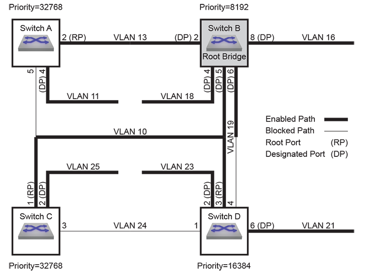
- Switch B is the root bridge its bridge ID is lowest because it has the smallest port priority.
- Switch A is the designated bridge for VLAN 11.
- Switch B is the designated bridge for VLAN 10, VLAN 13, VLAN 16, VLAN 18, VLAN 19.
- Switch C is the designated bridge for VLAN 25.
- Switch D is the designated bridge for VLAN 21, VLAN 23.
Port Roles
Messages from connected devices to the root bridge traverse a least-cost path, which has the smallest cost among all possible paths to the root bridge. The cost of a path is the sum of the costs of all path segments, as defined through port cost settings.
- Root Port (RP) accesses the bridges least-cost path to the root bridge. Each
bridge selects its root port after calculating the cost of each possible path to
the root bridge.
The following ports in Spanning Tree Network Example are root ports:
- Switch A: port 2
- Switch C: port 1
- Switch D: port 3
- Designated Port (DP) accesses a network segments designated bridge. Each segment
defines one DP. Switches can provide DPs for multiple segments. All ports on the
root bridge are DPs.
The following ports in Spanning Tree Network Example are designated ports:
- Switch A: port 4 (VLAN 11)
- Switch B: port 2 (VLAN 13), port 4 (VLAN 18), port 5 (VLAN 10), port 6 (VLAN 19), port 8 (VLAN 16)
- Switch C: port 2 (VLAN 25)
- Switch D: port 2 (VLAN 23), port 6 (VLAN 21)
- Alternate ports provide backup paths from their bridges to the root bridge. An alternate port is blocked until a network change transforms it into a root port.
- Backup ports provide alternative paths from VLANs to their designated bridges. A backup port is blocked until a network change transforms it into a designated port.
Port Activity States
A ports activity state defines its current STP activity level. STP monitors BPDUs for network changes that require an activity state transition.
- Forwarding: The port receives and sends data. Root ports and designated ports are either in, or transitioning to, this state.
- Discarding: The port does not receive or send data. Blocked ports receive BPDU packets. All ports except RPs and DPs are blocked, including alternate and backup ports.
- Learning: The transitional post-discarding state where the port prepares to forward frames by adding source addresses from inbound data packets to the switching database.
Port Types
- Normal ports have an unspecified topology.
- Network ports connect only to switches or bridges.
RSTP immediately transitions network ports to the discarding state.
- Edge ports connect directly to end stations.
Edge ports transition directly to forwarding state because they do not create loops. An edge port becomes a normal port when it receives a BPDU.
Link Types
- The default link type for full-duplex ports is point-to-point.
- The default link type for half-duplex ports is shared.
Fast state transitions are allowed on point-to-point links that connect bridges. Fast state transitions are not allowed on shared ports regardless of the duplex setting.
Bridge Protocol Data Units (BPDUs)
Spanning tree rules specify a root bridge, select designated bridges, and assign roles to ports. STP rule implementation requires that network topology information is available to each switch.
Switches exchange topology information through Bridge Protocol Data Units (BPDUs). Information provided by BPDU packets include bridge IDs and root path costs.
BPDU Types
- Configuration BPDU (CBPDU), used for computing the spanning tree.
- Topology Change Notification (TCN) BPDU, announces network topology changes.
- Topology Change Notification Acknowledgment (TCA), acknowledges topology changes.
- Source address: outbound port’s MAC address.
- Destination address: STP multicast address 01:80:C2:00:00:00.
Bridges regularly exchange BPDUs to track network changes that trigger STP recomputations and port activity state transitions. The hello timer specifies the period between consecutive BPDU messages; the default is two seconds.
Bridge Timers
- hello-time: transmission interval between consecutive BPDU packets.
- forward-time: the period that ports remain in learning state.
- max-age: the period that BPDU data remains valid after it is received.
- max-hop: the number of bridges in an MST region that a BPDU can traverse before it is discarded.
The switch recomputes the spanning tree topology if it does not receive another BPDU before the max-age timer expires. When edge ports and point-to-point links are properly configured, RSTP network convergence does not require forward-delay and max-age timers.
MSTP BPDUs
MSTP BPDUs are targeted at a single instance and provide STP information for the entire region. MSTP encodes a standard BPDU for the IST, then adds region information and MST instance messages for all configured instances, where each message conveys spanning tree data for an instance. Frames assigned to VLANs operate in the instance to which the VLAN is assigned. Bridges enter an MD5 digest of the VLAN-to-instance map table in BPDUs to avoid including the entire table in each BPDU. Recipients use this digest and other administratively configured values to identify bridges in the same MST region.
- RSTP bridges interpret MSTP BPDUs as RSTP BPDUs.
- RSTP bridges increment the message age timer only once while data flows through an MST region; MSTP measures time to live with a remaining hops variable, instead of the message age timer.
Ports at the edge of an MST region connecting to a bridge (RSTP or STP) or to an endpoint are boundary ports.
Configuring a Spanning Tree
Version Configuration and Instance Creation
The switch supports three STP versions and switchport backup interface pairs. Disabling spanning tree is also supported but not recommended.
The spanning-tree mode global configuration command specifies the spanning tree version the switch runs. This section describes command options that enable and configure STP versions.
Multiple Spanning Tree (MST)
Multiple Spanning Tree is enabled by the spanning-tree mode command with the mstp option. MSTP is the default STP version.
Example
switch(config)# spanning-tree mode mstp
switch(config)#
Configuring MST Regions
All switches in an MST region must have the same name, revision, and VLAN-to-instance map. Changes to one MST instance will cause the spanning tree to be recalculated, affecting other MST instances and causing traffic disruption in other VLANs, unless the same changes are applied to all switches. MST configuration mode commands sets the region parameters. The MST configuration mode is a group-change mode where changes are saved by exiting the mode.
Example
switch(config)# spanning-tree mst configuration
switch(config-mst)#
The instance command assigns VLANs to MST instances. The name (mst-configuration mode) and revision (mst-configuration mode) commands configure the MST region name and revision.
- These commands assign vlans 4-7 and
9 to instance 8
and remove vlan 6 from instance
10.
switch(config-mst)# instance 8 vlans 4-7,9 switch(config-mst)#no instance 10 vlans 6 switch(config-mst)# - These commands assign the name
(corporate_1) and revision
(3) to the
switch.
switch(config-mst)# name corporate_1
switch(config-mst)# revision 3
switch(config-mst)#
The exit (mst-configuration mode) command transitions the switch out of the MST configuration mode and saves all pending changes. The abort (mst-configuration mode) command exits the MST configuration mode without saving the pending changes.
Example
switch(config-mst)# exit
switch(config)#
Configuring MST Instances
- This command configures priority for MST instance
4.
switch(config)# spanning-tree mst 4 priority 4096 switch(config)# - Each of these commands configure priority for MST instance
0.
switch(config)# spanning-tree mst 0 priority 4096or
-
switch(config)# spanning-tree priority 4096
Rapid Spanning Tree (RST)
Rapid spanning tree is enabled through the spanning-tree mode command with the rstp option.
Example
- This command enables Rapid Spanning
Tree.
switch(config)#spanning-tree mode rstp
switch(config)#
These STP commands, when they do not include an optional MST or VLAN parameter, apply to RSTP. Commands that configure MSTP instance 0 also apply to the RSTP instance.
- These commands apply to the RST
instance.
switch(config)# spanning-tree priority 4096and
switch(config)# spanning-tree mst 0 priority 4096 - These commands do not apply to the RST
instance.
switch(config)# spanning-tree mst 4 priority 4096and
switch(config)# spanning-tree vlan-id 3 priority 4096
Show commands (such as show spanning-tree) displays the RSTP instance as MST0 (MST instance 0).
- This command, while the switch is in RST mode, displays RST instance
information.
switch(config)# show spanning-tree
MST0
  Spanning tree enabled protocol rstp <---RSTP mode indicator
  Root ID    Priority    32768
             Address     001c.730c.1867
             This bridge is the root

  Bridge ID  Priority    32768  (priority 32768 sys-id-ext 0)
             Address     001c.730c.1867
             Hello Time  2.000 sec  Max Age 20 sec  Forward Delay 15 sec

Interface        Role       State      Cost      Prio.Nbr Type
---------------- ---------- ---------- --------- -------- -----
Et51             designated forwarding 2000      128.51   P2p

switch(config)#
Rapid Per-VLAN Spanning Tree (Rapid-PVST)
Rapid-PVST mode is enabled by the spanning-tree mode command with the rapid-pvst option.
Example
- This command enables Rapid Per-VLAN Spanning
Tree.
switch(config)# spanning-tree mode rapid-pvst
switch(config)#
- This command configures bridge priority for vlan
4.
switch(config)# spanning-tree vlan-id 4 priority 4096 switch(config)# - This command enables MSTP PVST+ border ports. The command is effective only if
spanning-tree mode is
MSTP.
switch(config)# spanning-tree mst pvst border
Switchport Backup Mode
Switchport backup interface pairs are enabled through the spanning-tree mode command with the backup option. Enabling switchport backup disables all spanning-tree modes. For loop avoidance under switchport backup mode, use the Loop Protection feature.
Example
switch(config)# spanning-tree mode backup
switch(config)#
The switchport backup-link command establishes an interface pair between the command mode interface (primary) and the interface specified by the command (backup).
Example
switch(config)# interface ethernet 1
switch(config-if-Et1)# switchport backup-link ethernet 7
switch(config-if-Et1)#
The prefer option of the switchport backup-link command establishes a peer relationship between the primary and backup interfaces and specifies VLAN traffic that the backup interface normally carries. If either interface goes down, the other interface carries traffic normally handled by both interfaces.
Examples
- configures interface ethernet 1 as a trunk port that handles VLANs 4 through 9 traffic.
- configures interface ethernet 2 as the backup interface.
- assigns ethernet 2 as the preferred interface for VLANs 7 through 9.
- Enter configuration mode for the primary interface.
switch(config)# interface ethernet 1 - Configure the primary interface as a trunk port that services VLANs
4-9
switch(config-if-Et1)# switchport mode trunk switch(config-if-Et1)# switchport trunk allowed vlan 4-9 - Configure the backup interface and specify the VLANs that it normally
services.
switch(config-if-Et1)# switchport backup-link Ethernet 2 prefer vlan 7-9
switch(config-if-Et1)#
Loop Protection
Loop protection is a loop detection and prevention method which is independent of STP and is not disabled when the switch is in switchport backup mode. When loop protection is active on an interface, that interface periodically sends out loop-detection frames; if one is received that originated on the switch, the receiving port is errdisabled until a timeout period has passed or it is manually reset.
Loop protection is configured and enabled per VLAN, but individual ports in a VLAN can be configured to disable loop protection.
This feature is disabled by default. To enable it, use the monitor loop-protection command to enter loop-protection configuration mode, then use the no shutdown (Loop-protection) command to enable the feature. To enable loop protection on a VLAN, use the protect vlan command. To exclude a port from loop protection, use the no loop-protection command.
- This command enters loop protection configuration
mode.
switch(config)# monitor loop-protection switch(config-monitor-loop-protect)# - These commands enable loop protection on VLANs
1025-2000.
switch(config)# monitor loop-protection switch(config-monitor-loop-protect)# no shutdown switch(config-monitor-loop-protect)# protect vlan 1025-2000 switch(config-monitor-loop-protect)# - These commands exclude interface ethernet 38 from loop
protection.
switch(config)# interface ethernet 38 switch(config-if-Et38)# no loop-protection switch(config-if-Et38)# - These commands configure loop protection with a transmission interval of
10 seconds, a disabled time of two days, and a
maximum rate of 500 loop detection frames per second.
switch(config-monitor-loop-protect)# transmit-interval 10
switch(config-monitor-loop-protect)# disabled-time 172800
switch(config-monitor-loop-protect)# rate-limit 500
switch(config-monitor-loop-protect)#
Disabling Spanning Tree
Spanning tree is disabled by the spanning-tree mode command with the none option. The switch does not generate STP packets. Switchport interfaces forward packets when connected to other ports. The switch forwards inbound STP packets as multicast data packets on the VLAN where they are received.
Example
switch(config)# spanning-tree mode none
switch(config)#
Spanning Tree Instance Configuration
A network performs these steps to set up an STP instance:
Root Bridge Parameters
- Priority (four bits)
Priority is expressed as a multiple of 4096 because it is stored as the four most significant bits of a two-byte number.
- Protocol Dependent (twelve bits)
- Rapid-PVST: VLAN number
- MST: Instance number
- RST: 0
- MAC address of switch (six bytes)
Example
- MST 0: 32768 (Priority (32768)+Instance number(0)) and 001c.7301.23de (MAC address)
- MST101: 32869 (Priority (32768)+Instance number(101)) and 001c.7301.23de (MAC address)
- MST102: 32870 (Priority (32768)+Instance number(102)) and 001c.7301.23de (MAC address)
This command displays a table of root bridge information.
switch> show spanning-tree root
                Root ID          Root    Hello  Max  Fwd
Instance    Priority    MAC addr Cost    Time   Age  Dly  Root Port
----------  -------------------- ------ -----   ---  ---  ----------
MST0         32768 001c.7301.23de     0    2    20  15   Po937
MST101       32869 001c.7301.23de  3998    0     0   0   Po909
MST102 32870 001c.7301.23de 3998 0 0 0 Po911- spanning-tree priority options are integer multiples of 4096 between 0 and 61440.
- spanning-tree root options are primary and secondary.
- primary assigns a priority of 8192.
- secondary assigns a priority of 16384.
The default priority value is 32768.
The following examples configure bridge IDs with both commands.
- These commands configure MST instance bridge priorities with the
root
command:
switch(config)# spanning-tree mst 0 root primary switch(config)# spanning-tree mst 1 root secondary switch> show spanning-tree root Root ID Root Hello Max Fwd Instance Priority MAC addr Cost Time Age Dly Root Port ---------- -------------------- ------- ----- --- --- ---------- MST0 8192 001c.7301.6017 0 2 20 15 None MST1 16385 001c.7301.6017 0 0 0 0 None MST2 32770 001c.7301.6017 0 0 0 0 None- Instance 0 root priority is 8192: primary priority plus the instance number of 0.
- Instance 1 root priority is 16385: secondary priority plus the instance number of 1.
- Instance 2 root priority is
32770: default priority plus the
instance number of 2.
These priority settings normally program the switch to be the primary root bridge for instance 0, the secondary root bridge for instance 1, and a normal bridge for instance 2. Primary and secondary root bridge elections also depend on the configuration of other network bridges.
- These priority commands configure Rapid-PVST VLAN bridge
priorities:
switch(config)# spanning-tree vlan-id 1 priority 8192 switch(config)# spanning-tree vlan-id 2 priority 16384 switch(config)# spanning-tree vlan-id 3 priority 8192 switch(config)# no spanning-tree vlan-id 4 priority switch(config)# show spanning-tree root Root ID Root Hello Max Fwd Instance Priority MAC addr Cost Time Age Dly Root Port ---------- -------------------- ------- ----- --- --- ---------- VL18193 001c.7301.6017 0 2 20 15 None VL216386 001c.7301.6017 0 2 20 15 None VL38195 001c.7301.6017 0 2 20 15 None VL432788 001c.7301.6017 0 2 20 15 None- VLAN 1 root priority is 8193: configured priority plus the VLAN number of 1.
- VLAN 2 root priority is 16386: configured priority plus the VLAN number of 2.
- VLAN 3 root priority is
8195: configured priority plus the
VLAN number of 3.
These priority settings normally program the switch to be the primary root bridge for VLANs 1 and 3, the secondary root bridge for vlan 2, and a normal bridge for vlan 4. Primary and secondary root bridge elections also depend on the configuration of other network bridges.vlan 4 root priority is 32788: default priority plus the VLAN number of 4.
Path Cost
Spanning tree calculates the costs of all possible paths from each component to the root bridge. The path cost is equal to the sum of the cost assigned to each port in the path. Ports are assigned a cost by default or through CLI commands. Cost values range from 1 to 200000000 (200 million).
- 1 gigabit interfaces have a default cost of 20000.
- 10 gigabit interfaces have a default cost of 2000.
The spanning-tree cost command configures the path cost of the configuration mode interface. Costs can be specified for Ethernet and port channel interfaces. The command provides a mode parameter for assigning multiple costs to a port for MST instances or Rapid-PVST VLANs.
- These commands configure a port cost of 25000 to
interface ethernet 5. This cost is valid for
RSTP or MSTP instance
0.
switch(config)# interface ethernet 5 switch(config-if-Et5)# spanning-tree cost 25000 switch(config-if-Et5)# - This command configures a path cost of 300000 to
interface ethernet 5 in MST instance
200.
switch(config)# interface ethernet 5 switch(config-if-Et5)# spanning-tree mst 200 cost 300000 switch(config-if-Et5)# - This command configures a path cost of 10000 to
interface ethernet 5 in Rapid-PVST VLAN
200-220.
switch(config)# interface ethernet 5
switch(config-if-Et5)# spanning-tree vlan-id 200-220 cost 10000
switch(config-if-Et5)#
Port Priority
STP uses the port priority interface parameter to select ports when resolving loops. The port with the lower port priority numerical value is placed in forwarding mode. When multiple ports are assigned equal port priority numbers, the port with the lower interface number is placed in forwarding mode. Valid port-priority numbers are multiples of 16 between 0 and 240; the default is 128.
The spanning-tree port-priority command configures the port-priority number for the configuration mode interface. The command provides a mode option for assigning different priority numbers to a port for multiple MST instances or Rapid-PVST VLANs. Port-priority can be specified for Ethernet and port channel interfaces.
- This command sets the access port priority of
144 for Ethernet 5
interface.
switch(config)# interface ethernet 5 switch(config-if-Et5)# spanning-tree port-priority 144 switch(config-if-Et5)# - This command sets the access port priority of
144 for Ethernet 5 interface in
MST instance
10.
switch(config)# interface ethernet 5
switch(config-if-Et5)# spanning-tree mst 10 port-priority 144
switch(config-if-Et5)#
Port Roles and Rapid Convergence
- portfast: Allows ports to skip learning state before entering the forwarding state.
- port type and link type: Designates ports for rapid transitions to the forwarding state.
- root guard: Ensures that a port will not become the root port.
- loop guard: Prevents loops resulting from unidirectional failure of links.
- bridge assurance: Prevents loops caused by unidirectional links or a malfunctioning switch.
PortFast
PortFast allows devices to gain immediate network access before convergence of the spanning tree. Enabling PortFast on ports connected to another switch can create loops.
A portfast port that receives a BPDU sets its operating state to non-portfast while remaining in portfast configured state. In this state, the port is subject to topology changes and can enter the discarding state.
The spanning-tree portfast command programs access ports to immediately enter the forwarding state. PortFast connects devices attached to an access port, such as a single workstation, to the network immediately without waiting for STP convergence. PortFast can also be enabled on trunk ports.
Example
switch(config)# interface ethernet 5
switch(config-if-Et5)# spanning-tree portfast
switch(config-if-Et5)#
Port Type and Link Type Configuration
RSTP only achieves rapid transition to forwarding state on edge ports and point-to-point links.
Port Type
Edge ports are directly connected to end stations. Because edge ports do not create loops, they transition directly to forwarding state when a link is established.
- edge ports connect to a host (end station). Configuring a port that connects to a bridge as an edge port may create a loop. Edge ports that receive a BPDU become a normal spanning tree port.
- network ports connect only to a Layer 2 switch or bridge. Configuring a port connected to a host as a network port transitions the port to the discarding state.
- normal ports have an unspecified topology.
Examples
- This command configures interface ethernet 5 as a
network
port.
switch(config)# interface ethernet 5 switch(config-if-Et5)# spanning-tree portfast network switch(config-if-Et5)# -
Auto-edge detection converts ports into edge ports when they do not receive a new BPDU before the current BPDU expires, as measured by the max-age timer. The spanning-tree portfast auto command enables auto-edge detection on the configuration mode interface, superseding the spanning-tree portfast command. Auto-edge detection is enabled by default.
This command enables auto-edge detection on interface ethernet 5.switch(config)# interface ethernet 5 switch(config-if-Et5)# spanning-tree portfast auto switch(config-if-Et5)#
Link Type
- full-duplex ports are point-to-point.
- half-duplex ports are shared link.
The spanning-tree link-type command specifies the configuration mode interfaces link-type. RSTP fast transition is not allowed on shared link ports, regardless of their duplex setting. Because the ports are full-duplex by default, the default link-type setting is point-to-point.
Example
switch(config)# interface ethernet 5
switch(config-if-Et5)# spanning-tree link-type shared
switch(config-if-Et5)#Root Guard and Loop Guard
Root guard stops a port from becoming a root port, which stops connected switches from becoming root bridges. When a switch detects a new root bridge, its root-guard-enabled ports enter blocked (root-inconsistent) state. When the switch no longer detects a new root, these ports enter learning state.
Root guard is enabled on a per-port basis. The setting applies to all STP instances. Disabling root guard places the port in learning state.
The spanning-tree guard command, with the root option, enables root guard on the configuration mode interface.
Example
switch(config)# interface ethernet 5
switch(config-if-Et5)# spanning-tree guard root
switch(config-if-Et5)#Loop guard prevents loops resulting from unidirectional failure of point-to-point links by verifying that non-designated ports (root, blocked, and alternate) are receiving BPDUs from their designated ports. A loop-guard-enabled root or blocked port that stops receiving BPDUs transitions to the discarding (loop-inconsistent) state. The port recovers from this state when it receives a BPDU.
Loop guard, when enabled globally, applies to all point-to-point ports. Loop guard is configurable on individual ports and applies to all STP instances of an enabled port. Loop-inconsistent ports transition to learning state when loop guard is disabled.
If loop guard is enabled on a root switch, it takes effect only if the switch becomes a nonroot switch.
- Do not enable loop guard on portfast-enabled ports.
- Loop guard is not functional on ports not connected to point-to-point links.
- Loop guard has no effect on disabled spanning tree instances.
- BPDUs are sent over the channels first operational port. Loop guard blocks the channel if that link becomes unidirectional even when other channel links function properly.
- Creating a new channel destroys state information for its component ports; new channels with loop-guard-enabled ports can enter forwarding state as a DP.
- Dissembling a channel destroys its state information; component ports from a blocked channel can enter the forwarding state as DPs, even if the channel contained unidirectional links.
- If a link on any port of the channel becomes unidirectional, the channel is blocked. Transmission resumes if the port is removed from the channel or the bidirectional communication is restored.
- spanning-tree guard loop default command enables loop guard as a default on all switch ports.
- spanning-tree guard control the loop guard setting on the configuration mode interface. This command overrides the default command for the specified interface.
- This command enables loop guard as the default
on all switch
ports.
switch(config)# spanning-tree guard loop default switch(config)# - This command enables loop guard on
interface ethernet
6.
switch(config)# interface ethernet 6 switch(config-if-Et6)# spanning-tree guard loop switch(config-if-Et6)#
Bridge Assurance
Bridge assurance protects against unidirectional link failures, other software failures, and devices that continue forwarding data traffic after they quit running spanning tree.
Bridge assurance programs the switch to send BPDUs at each hello time period through all bridge assurance-enabled ports (i.e., network ports). Bridge assurance operates only on network ports with point-to-point links, ideally with bridge assurance enabled on each side of the link. Bridge assurance-enabled ports will not necessarily be blocked when they link to a port where bridge assurance is not enabled.
Ports not receiving a BPDU packet within a hello time period enter inconsistent (blocking) state. In this case, the show spanning-tree transmit active command will show a bridge assurance status of inconsistent for the port. If the other side of the link has bridge assurance enabled, or if the other switch is the root bridge, it will send periodic BPDUs, preventing an inconsistent blocking state.
Bridge assurance is globally enabled by default, but must also be enabled on a per-port basis by designating the port as a network port with the spanning-tree portfast <port type> command. The no spanning-tree transmit active command disables bridge assurance globally.
Example
switch(config)# spanning-tree transmit active
switch(config)# interface ethernet 5
switch(config-if-Et5)# spanning-tree portfast network
switch(config-if-Et5)#Configuring BPDU Transmissions
The following sections describe instructions that configure BPDU packet contents and transmissions.
Configuring Bridge Timers
- hello-time: transmission interval between consecutive BPDU packets.
- forward-time: the period that ports remain in learning state.
- max-age: the period that BPDU data remains valid after it is received.
- max-hop: the number of bridges in an MST region that a BPDU can traverse before it is discarded.
In standard STP, ports passively wait for forward_delay and max_age periods before entering the forwarding state. RSTP achieves faster convergence by relying on edge port and link type definitions to start forwarding traffic. When edge ports and link types are properly configured, bridge timers are used in RSTP as backup or when interacting with networks running standard STP.
The spanning-tree hello-time command configures the hello time.
-
This command configures a hello-time of 1 second (1000 ms).
switch(config)# spanning-tree hello-time 1000 switch(config)#The spanning-tree max-hops command specifies the max hop setting that the switch inserts into BPDUs that it sends out as the root bridge.
-
This command sets the max hop value to 40.
switch(config)# spanning-tree max-hops 40 switch(config)#The spanning-tree forward-time command configures the forward delay setting that the switch inserts into BPDUs that it sends out as the root bridge.
-
This command sets the forward delay timer value to 25 seconds.
switch(config)# spanning-tree forward-time 25 switch(config)#The spanning-tree max-age command configures the max age setting that the switch inserts into BPDUs that it sends out as the root bridge.
-
This command sets the max age timer value to 25 seconds.
switch(config)# spanning-tree max-age 25 switch(config)#
BPDU Transmit Hold-Count
The spanning-tree bpdu tx hold-count command specifies the maximum number of BPDUs per second that the switch can send from an interface. Valid settings range from 1 to 10 BPDUs with a default of 6 BPDUs.
Higher hold-count settings can significantly impact CPU utilization, especially in Rapid-PVST mode. Smaller values can slow convergence in some configurations.
Example
switch(config)# spanning-tree bpdu tx hold-count 8
switch(config)#BPDU Guard
- When configured globally, BPDU Guard is enabled on ports in the operational portfast state.
- When configured on an individual interface, BPDU Guard disables the port when it receives a BPDU, regardless of the portfast state of the port.
The spanning-tree edge-port bpduguard default global configuration command enables BPDU Guard by default on all portfast ports. BPDU Guard is disabled on all ports by default.
- spanning-tree bpduguard enables BPDU Guard on the configuration mode interface.
- spanning-tree bpduguard disable disables BPDU Guard on the configuration mode interface.
- no spanning-tree bpduguard reverts the configuration mode interface to the default BPDU Guard setting.
Example
switch(config)# spanning-tree edge-port bpduguard default
switch(config)# interface ethernet 5
switch(config-if-Et5)# spanning-tree bpduguard disable
switch(config-if-Et5)BPDU Filter
BPDU filtering prevents the switch from sending or receiving BPDUs on specified ports. BPDU filtering is configurable on Ethernet and port channel interfaces.
Ports with BPDU filtering enabled do not send BPDUs and drops inbound BPDUs. Enabling BPDU filtering on a port not connected to a host can result in loops as the port continues forwarding data while ignoring inbound BPDU packets.
The spanning-tree bpdufilter command controls BPDU filtering on the configuration mode interface. BPDU filtering is disabled by default.
Example
switch(config)# interface ethernet 5
switch(config-if-Et5)# spanning-tree bpdufilter enable
switch(config-if-Et5)#BPDU Rate Limit
BPDU input rate limiting restricts the number of BPDUs that a port on which BPDU
Guard and BPDU Filter are both disabled accepts during a specified interval. If the
number of BPDUs received on the port during the configured interval exceeds the
limit, the port will be error disabled with the cause listed as
bpduguard.
- Establishing the rate limit threshold
- Enabling rate limiting
Establishing the Rate Limit Threshold
- The spanning-tree bpduguard rate-limit count
global command specifies the maximum reception rate for ports that are not
covered by interface rate limit count commands. The global command specifies
the default limit.Note: Arista Networks recommends retaining the default rate-limit values. In the PVST mode, when the VLAN membership of a port is changed by a significant margin, it is advisable to disable interface BPDU rate limiting on both ends of a port. For example, if three VLANs are present on a port initially, the operator must first add 300 more VLANs on one side of the port and then add the same 300 VLANs on the other side of the port. In this case, if the VLANs are increased towards the root bridge first, then the other side can cross the rate-limit threshold.
- The spanning-tree bpduguard rate-limit count interface command defines the maximum BPDU reception rate for ports in the configuration mode interface.
- This command configures the global limit of 5000
BPDUs over a 4 second
interval.
switch(config)# spanning-tree bpduguard rate-limit count 5000 interval 4 switch(config)# - These commands configure a limit of 7500 BPDUs
over an 8 second interval on the
interface ethernet
2.
switch(config)# interface ethernet 2 switch(config-if-Et2)# spanning-tree bpduguard rate-limit count 7500 interval 8 switch(config-if-Et2)#
Enabling Rate Limiting
- spanning-tree bpduguard rate-limit default enables rate limiting on all ports that are not covered by the interface rate limiting command. The default setting is enabled.
- spanning-tree bpduguard rate-limit enable / disable interface command enables or disables BPDU rate limiting on the configuration mode interface. This command has precedence over the global command.
- This command enables rate limiting on ports that are not covered by
interface rate limit
commands:
switch(config)# spanning-tree bpduguard rate-limit default switch(config)# - These commands enable rate limiting on the interface ethernet
15:
switch(config)# interface ethernet 15 switch(config-if-Et15)# spanning-tree bpduguard rate-limit enable switch(config-if-Et15)#
STP Commands
Spanning Tree Commands: Global Configuration
- spanning-tree bpdu tx hold-count
- spanning-tree bpduguard rate-limit count (global)
- spanning-tree bpduguard rate-limit default
- spanning-tree edge-port bpdufilter default
- spanning-tree edge-port bpduguard default
- spanning-tree forward-time
- spanning-tree guard loop default
- spanning-tree hello-time
- spanning-tree max-age
- spanning-tree max-hops
- spanning-tree mode
- spanning-tree mst configuration
- spanning-tree mst pvst border
- spanning-tree portchannel guard misconfig
- spanning-tree priority
- spanning-tree root
- spanning-tree transmit active
- spanning-tree vlan-id
Loop Protection Commands
Spanning Tree Commands: Interface Configuration Mode
- spanning-tree bpdufilter
- spanning-tree bpduguard
- spanning-tree bpduguard rate-limit count (interface)
- spanning-tree bpduguard rate-limit enable / disable
- spanning-tree cost
- spanning-tree guard
- spanning-tree link-type
- spanning-tree port-priority
- spanning-tree portfast
- spanning-tree portfast <port type>
- switchport backup-link
MST Configuration Commands
Display Commands
- show spanning-tree
- show spanning-tree blockedports
- show spanning-tree counters
- show spanning-tree instance
- show spanning-tree instance detail
- show spanning-tree interface
- show spanning-tree mst
- show spanning-tree mst configuration
- show spanning-tree mst interface
- show spanning-tree mst test information
- show spanning-tree root
- show spanning-tree topology status
- show spanning-tree transmit active
Clear Commands
abort (mst-configuration mode)
The abort command, in MST-configuration mode, discards pending changes to the MST region configuration, then returns the switch to global configuration mode.
The exit (mst-configuration mode) command saves MST region changes to running-config before returning the switch to global configuration mode.
Command Mode
MST-configuration
Command Syntax
abort
Example
switch(config-mst)# abort
switch(config)#clear spanning-tree counters
The clear spanning-tree counters command resets the BPDU counters for the specified interfaces to zero in all CLI sessions.
Command Mode
Privileged EXEC
Command Syntax
clear spanning-tree counters [INT_NAME]
Parameters
- no parameter resets counters for all interfaces.
- interface ethernet e_num Ethernet interface specified by e_num.
- interface loopback l_num Loopback interface specified by l_num.
- interface management m_num Management interface specified by m_num.
- interface port-channel p_num Port-Channel Interface specified by p_num.
- interface vlan v_num VLAN interface specified by v_num.
Example
switch# show spanning-tree counters
Port Sent Received Tagged Error Other Error
---------------------------------------------------------------------
Ethernet15 32721 0 0 0
Port-Channel10 8487 0 0 0
switch# clear spanning-tree counters interface ethernet 15<---Clear command
switch# show spanning-tree counters
Port Sent Received Tagged Error Other Error
----------------------------------------------------------------------
Ethernet15 11 0 0 0
Port-Channel10 84942 6 0
switch#clear spanning-tree counters session
The clear spanning-tree counter session command resets the BPDU counters to zero on all interfaces in the current CLI session. Counters in other CLI sessions are not affected.
Command Mode
Privileged EXEC
Command Syntax
clear spanning-tree counters session
Example
switch# show spanning-tree counters
Port Sent Received Tagged Error Other Error
----------------------------------------------------------------------------
Ethernet15 32721 0 0 0
Port-Channel10 8487 0 0 0
switch# clear spanning-tree counters session
switch# show spanning-tree counters
Port Sent Received Tagged Error Other Error
----------------------------------------------------------------------------
Ethernet15 11 0 0 0
Port-Channel10 7 2 6 0
switch#clear spanning-tree detected-protocols
The clear spanning-tree detected-protocols command restarts the Spanning Tree Protocol (STP) migration state machine on the specified interfaces. The switch is reset to running rapid spanning tree protocol on an interface where it previously detected a bridge running an old version of the protocol.
Command Mode
Privileged EXEC
Command Syntax
clear spanning-tree detected-protocols [INT_NAME]
Parameters
- no parameter all interfaces.
- ethernet e_num Ethernet interface specified by e_num.
- loopback l_num Loopback interface specified by l_num.
- management m_num Management interface specified by m_num.
- port-channel p_num Port-Channel Interface specified by p_num.
- vlan v_num VLAN interface specified by v_num.
Example
switch# clear spanning-tree detected-protocols
switch#disabled-time
The disabled-time command sets the time for which the port remains disabled after a loop is detected by loop protection. The no disabled-time and default disabled-time commands reset the disabled time to the default of 604800 seconds (seven days).
Command Mode
Loop-protection Configuration
Command Syntax
disabled-time [period]
no disabled-time [period]
default disabled-time [period]
Parameter
period Time in seconds for which the port remains disabled. Values range from 0 to 604800 (seven days). Default is 604800. A value of 0 disables the interface until it is manually reset, even if the disabled time is later set to a non-zero value. To restore the port manually, shut it down and then re-enable it.
Example
switch(config-monitor-loop-protect)# disabled-time 172800
switch(config-monitor-loop-protect)#exit (mst-configuration mode)
The exit command, in MST-configuration mode, saves changes to the MST region configuration, then returns the switch to global configuration mode. MST region configuration changes are also saved by entering a different configuration mode.
Command Mode
MST-configuration
Command Syntax
exit
- This command saves changes to the MST region, then returns the switch to
global configuration
mode.
switch(config-mst)# exit switch(config)# - This command saves changes to the MST region, then places the switch in
Interface-Ethernet
mode.
switch(config-mst)# interface ethernet 3 switch(config-if-Et3)#
instance
The instance command inserts an entry into the VLAN-to-instance map that associates a set of VLANs to an MST instance. In addition to defining the MST topology, the VLAN-to-instance map is one of three parameters, along with the MST name and revision number, that identifies the switchs MST region.
The no instance command removes specified entries from the VLAN-to-instance map. If the command does not provide a VLAN list, all entries are removed for the specified instance. The no instance and default instance commands function identically.
Command Mode
MST-Configuration
Command Syntax
instance mst_inst vlans v_range
no instance mst_inst [vlans v_range]
no default instance mst_inst [vlans v_range]
- mst_inst MST instance number. Value of mst_inst ranges from 0 to 4094.
- v_range VLAN list. Formats include a number, number range, or comma-delimited list of numbers and ranges.
- This command maps VLANs 20-39 to MST instance
2.
switch(config)# spanning-tree mst configuration switch(config-mst)# instance 2 vlans 20-39 switch(config-mst)# - This command removes all VLAN mappings to MST instance
10.
switch(config-mst)# no instance 10 switch(config-mst)#
loop-protection
The loop-protection command enables loop protection on the configuration mode interface. All interfaces in a VLAN under loop protection have loop protection enabled by default. The no loop-protection and default loop-protection commands disable loop protection on the interface.
When loop protection is disabled (at the VLAN or interface level), the computed state of the interface is forgotten and packets queued to be sent are dropped. If an interface is err-disabled by loop protection, disabling loop protection removes the err-disable.
Command Mode
Interface-Ethernet Configuration
Command Syntax
loop-protection
no loop-protection
default loop-protection
Example
switch(config)# interface ethernet 2/4
switch(config-if-Et2/4)# no loop-protection
switch(config-if-Et2/4)#monitor loop-protection
The monitor loop-protection command places the switch in loop-protection configuration mode.
Command Mode
Global Configuration
Command Syntax
monitor loop-protection
Example
switch(config)# monitor loop-protection
switch(config-monitor-loop-protect)#name (mst-configuration mode)
The name command configures the MST region name. The name is one of three parameters, along with the MST revision number and VLAN-to-instance map, that identifies the switchs MST region.
The name has up to 32 characters. The default name is an empty string. The name string accepts all characters except the space.
The no name and default name commands restore the default name by removing the name command from running-config.
Command Mode
MST-Configuration
Command Syntax
name label_text
no name
default name
Parameter
label_text character string assigned to name attribute. Maximum 32 characters. The space character is not permitted in the name string.
Example
switch(config)# spanning-tree mst configuration
switch(config-mst)# name corporate_100
switch(config-mst)# show pending
Active MST configuration
Name [corporate_100]
Revision 0 Instances configured 1
Instance Vlans mapped
---------------------------------------------------------
0 1-4094
---------------------------------------------------------protect vlan
The protect vlan command specifies which VLANs participate in loop protection. The no protect vlan and default protect vlan commands remove loop protection from the specified VLANs.
Command Mode
Loop-protection Configuration
Command Syntax
protect vlan vlan-range
Parameter
vlan-range List of VLANs (number, range, comma-delimited list of numbers and ranges). Numbers range from 1 to 4094.
Example
switch(config-monitor-loop-protect)# protect vlan 1025-2000
switch(config-monitor-loop-protect)#rate-limit
The rate-limit command sets the maximum number of loop detection frames which can be sent by the switch per second. The no rate-limit and default rate-limit commands return the rate limit to the default value of 1000.
Command Mode
Loop-protection Configuration
Command Syntax
rate-limit [frames]
no rate-limit [frames]
default rate-limit [frames]
Parameters
frames Maximum number of frames sent per second. Values range from 0-1000, default is 1000. A value of 0 disables throttling.
Example
switch(config-monitor-loop-protect)# rate-limit 500
switch(config-monitor-loop-protect)#revision (mst-configuration mode)
The revision command configures the MST revision number. The revision number is one of three parameters, along with the MST name and VLAN-to-instance map, that identifies the switchs MST region. Revision numbers range from 0 to 65535. The default revision number is 0.
The no revision and default revision commands restore the revision number to its default value by removing the revision command from running-config.
Command Mode
MST-Configuration
Command Syntax
revision rev_number
no revision
default revision
Parameter
rev_number revision number. Possible ranges from 0 to 65535 with a default of 0.
Example
switch(config)# spanning-tree mst configuration
switch(config-mst)# revision 15
switch(config-mst)# show pending
Active MST configuration
Name []
Revision 15Instances configured 1
Instance Vlans mapped
-------- --------------------------------------------------
0 1-4094
------------------------------------------------------------show (mst-configuration mode)
The show command displays the current and pending MST configuration:
Exiting MST configuration mode stores all pending configuration changes to running-config.
Command Mode
MST-Configuration
Command Syntax
show [EDIT_VERSION]
Parameters
- no parameter command displays pending MST configuration.
- active command displays MST configuration stored in running-config.
- current command displays MST configuration stored in running-config.
- pending command displays pending MST configuration.
Example
switch(config-mst)# show pending
Active MST configuration
Name []
Revision 0 Instances configured 1
Instance Vlans mapped
------------------------------------------------------
0 1-4094
------------------------------------------------------
switch(config-mst)# instance 2 vlan 20-29,102
switch(config-mst)# revision 2
switch(config-mst)# name baseline
switch(config-mst)# show pending
Pending MST configuration
Name [baseline]
Revision 2 Instances configured 2
Instance Vlans mapped
-------------------------------------------------------
0 1-19,30-101,103-4094
2 20-29,102
-------------------------------------------------------
switch(config-mst)# show active
Active MST configuration
Name []
Revision 0 Instances configured 1
Instance Vlans mapped
--------------------------------------------------------
0 1-4094
--------------------------------------------------------show loop-protection
The show loop-protection command displays loop protection status.
Command Syntax
show loop-protection [detail]
- This command displays basic loop protection
information.
switch# show loop-protection Loop protection is enabled Transmit interval: 5 Disable Time: 604800(or Permanent) Packets Transmitted rate: 12/second(or Unthrottled) Total: 3 Vlans enabled. switch> - This command displays detailed information about loop
protection.
switch# show loop-protection detail Loop protection is enabled Transmit interval: 5 Disable Time: 604800 Packets Transmitted rate: 12/second Total: 3 Vlans enabled. Destination address: ffff.ffff.ffff Ethernet type: 0x88b7 Receive action: Interface Disable Vlan Loop Disabled Intfs Total Latest Detected Intfs Disabled Time ----------- --------- -------------- ----- ------------- 1 Yes Et1-2 20 18:01 2 No - 20 - 3 No - 20 - switch# - This command displays loop protection information for the interfaces in
VLANS
3-4.
switch# show loop-protection vlan 3-4 Vlan Intf LP Enabled State LP Disabled Bring Disabled at up at ----- ----- ---------- --------- ------- -------- ------ 3 Et1 Yes shutdown Yes 17:21 18:21 3 Et2 Yes shutdown No - - 3 Et3 Yes enabled No - - 3 Et4 No - - - - 4 - No - - - - switch# - This command displays the number of loop detection packets sent and
received.
switch# show loop-protection counters VLAN Tx Rx Rx-Other ------- ----- ---- -------- 2 200 0 100 3 200 1 0 Intfs Tx Rx Rx-Other ------- ----- ---- -------- Et1 200 0 100 Et2 200 1 0 switch#
show spanning-tree
The show spanning-tree command displays Spanning Tree Protocol (STP) data, organized by instance.
Command Mode
EXEC
Command Syntax
show spanning-tree [VLAN_ID][INFO_LEVEL]
- VLAN_ID specifies the VLANs for which the command
displays information. Formats include:
- no parameter displays information for all VLANs.
- vlan displays data for instances containing the first VLAN listed in running-config.
- vlan v_range displays data for instances containing a VLAN in the specified range.
- INFO_LEVEL specifies level of information detail
provided by the command.
- no parameter displays table for each instance listing status, configuration, and history.
- detail displays data blocks for each instance and all ports on each instance.
- Root ID Displays information on the ROOT
ID (elected spanning tree root bridge ID):
- Priority Priority of the bridge. Default value is 32768.
- Address MAC address of the bridge.
- Bridge ID bridge status and
configuration information for the locally configured bridge:
- Priority Priority of the bridge. The default priority is 32768.
- Address MAC address of the bridge.
- Hello Time Interval (seconds) between bridge protocol data units (BPDUs) transmissions.
- Max Age Maximum time that a BPDU is saved.
- Forward Delay Time (in seconds) that is spent in the learning state.
- Interface STP configuration participants. Link-down interfaces are not shown.
- Role Role of the port as one of the
following:
- Root The best port for a bridge to a root bridge used for forwarding.
- Designated A forwarding port for a LAN segment.
- Alternate A port acting as an alternate path to the root bridge.
- Backup A port acting as a redundant path to another bridge port.
- State Displays the interface STP state
as one of the following:
- Learning
- Discarding
- Forwarding
- Cost STP port path cost value.
- Prio. Nbr. STP port priority. Values range from 0 to 240. Default is 128.
- Type The link type of the interface
(automatically derived from the duplex mode of an interface):
- P2p Peer (STP) Point to point full duplex port running standard STP.
- shr Peer (STP) Shared half duplex port running standard STP.
- This command displays STP data, including a table of port
parameters.
switch# show spanning-tree vlan 1000 MST0 Spanning tree enabled protocol rstp Root ID Priority 32768 Address 001c.7301.07b9 Cost 1999 (Ext) 0 (Int) Port 101 (Port-Channel2) Hello Time 2.000 sec Max Age 20 sec Forward Delay 15 sec Bridge ID Priority 32768 (priority 32768 sys-id-ext 0) Address 001c.7304.195b Hello Time 2.000 sec Max Age 20 sec Forward Delay 15 sec Interface Role State Cost Prio.Nbr Type ---------------- ---------- ---------- --------- -------- -------------------- Et4 designated forwarding 20000 128.4 P2p Et5 designated forwarding 20000 128.5 P2p Et6 designated forwarding 20000 128.6 P2p Et23 designated forwarding 20000 128.23 P2p Et26 designated forwarding 20000 128.26 P2p Et32 designated forwarding 2000 128.32 P2p switch> - This command displays output from the show spanning-tree
command:
Switch# show spanning-tree MST0 Spanning tree enabled protocol mstp Root ID Priority 32768 Address 0011.2201.0301 This bridge is the root Bridge ID Priority 32768 (priority 32768 sys-id-ext 0) Address 0011.2201.0301 Hello Time 2 sec Max Age 20 sec Forward Delay 15 sec Interface Role State Cost Prio.Nbr Type --------------- ---------- ---------- --------- -------- -------------------- Et4 designated forwarding 2000 128.4 P2p Et5 designated forwarding 2000 128.5 P2p ... PEt4 designated forwarding 2000 128.31 P2p PEt5 designated forwarding 2000 128.44 P2p ... Po3 designated forwarding 1999 128.1003 P2p - This command displays STP data, including an information block for each
interface running
STP.
switch# show spanning-tree vlan 1000 detail MST0 is executing the rstp Spanning Tree protocol Bridge Identifier has priority 32768, sysid 0, address 001c.7304.195b Configured hello time 2.000, max age 20, forward delay 15, transmit hold-count 6 Current root has priority 32768, address 001c.7301.07b9 Root port is 101 (Port-Channel2), cost of root path is 1999 (Ext) 0 (Int) Number of topology changes 4109 last change occurred 1292651 seconds ago from Ethernet13 Port 4 (Ethernet4) of MST0 is designated forwarding Port path cost 20000, Port priority 128, Port Identifier 128.4. Designated root has priority 32768, address 001c.7301.07b9 Designated bridge has priority 32768, address 001c.7304.195b Designated port id is 128.4, designated path cost 1999 (Ext) 0 (Int) Timers: message age 1, forward delay 15, hold 20 Number of transitions to forwarding state: 1 Link type is point-to-point by default, Internal BPDU: sent 452252, received 0, taggedErr 0, otherErr 0, rateLimiterCount 0 Rate-Limiter: enabled, Window: 10 sec, Max-BPDU: 400 Port 5 (Ethernet5) of MST0 is designated forwarding Port path cost 20000, Port priority 128, Port Identifier 128.5. Designated root has priority 32768, address 001c.7301.07b9 Designated bridge has priority 32768, address 001c.7304.195b Designated port id is 128.5, designated path cost 1999 (Ext) 0 (Int) Timers: message age 1, forward delay 15, hold 20 Number of transitions to forwarding state: 1 Link type is point-to-point by default, Internal BPDU: sent 1006266, received 0, taggedErr 0, otherErr 0, rateLimiterCount 0 Rate-Limiter: enabled, Window: 10 sec, Max-BPDU: 400 switch#
show spanning-tree blockedports
The show spanning-tree blockedports command displays the list of blocked (discarding) ports.
Command Mode
EXEC
Command Syntax
show spanning-tree blockedports
Example
This command shows the ports that are in discarding state.
switch# show spanning-tree blockedports
Name Blocked Interfaces List
---------------------------------------------------------------------
MST0 Po903, Po905, Po907, Po909, Po911, Po913, Po915, Po917, Po919, Po921, Po923
Po925, Po927, Po929, Po931, Po933, Po935, Po939, Po941, Po943, Po945, Po947
Number of blocked ports (segments) in the system : 22
switch#show spanning-tree counters
The show spanning-tree counters command displays the number of BPDU transactions on each interface running spanning tree.
Command Mode
EXEC
Command Syntax
show spanning-tree counters
Example
switch# show spanning-tree counters
Port Sent Received Tagged Error Other Error sinceTimer
----------------------------------------------------------------------------
Ethernet2 1008399 0 0 0 0
Ethernet3 1008554 0 0 0 0
Ethernet4 454542 0 0 0 0
Ethernet5 1008556 0 0 0 0
Ethernet6 827133 0 0 0 0
Ethernet8 1008566 0 0 0 0
Ethernet10 390732 0 0 0 0
Ethernet11 1008559 0 0 0 0
Ethernet15 391379 0 0 0 0
Ethernet17 621253 0 0 0 0
Ethernet19 330855 0 0 0 0
Ethernet23 245243 0 0 0 0
Ethernet25 591695 0 0 0 0
Ethernet26 1007903 0 0 0 0
Ethernet32 1010429 8 0 0 0
Ethernet33 510227 0 0 0 0
Ethernet34 827136 0 0 0 0
Ethernet38 1008397 0 0 0 0
Ethernet39 1008564 0 0 0 0
Ethernet40 1008185 0 0 0 0
Ethernet41 1007467 0 0 0 0
Ethernet42 82925 0 0 0 0
Port-Channel1 1008551 0 0 0 0
Port-Channel2 334854 678589 0 0 3
Port-Channel3 1010420 4 0 0 0
switch#show spanning-tree instance
The show spanning-tree instance command displays spanning tree protocol bridge configuration settings for each instance on the switch. The display includes Bridge ID, Hello Time, Max Age, and Forward Delay times.
The command also displays the restartability of the STP agent when the detail option is selected. A switch can continue support of MLAG operation when its peer is offline and the STP agent is unavailable.
Command Mode
EXEC
Command Syntax
show spanning-tree instance [INFO_LEVEL]
Parameters
- no parameter command displays information in a data table.
- detail command displays bridge information in data blocks for each instance.
- This command displays a bridge data
table.
switch# show spanning-tree instance Bridge ID Hello Max Fwd Instance Priority MAC addr Time Age Dly ---------- ---------------------------------------- ----- --- --- MST0 32768(32768, sys-id 0 ) 001c.7302.2f98 2000 20 15 MST101 32869(32768, sys-id 101 ) 001c.7302.2f98 2000 20 15 MST102 32870(32768, sys-id 102 ) 001c.7302.2f98 2000 20 15 switch# - This command displays bridge data
blocks.
switch# show spanning-tree instance detail Stp Detailed Status: Stp agent restartable : True MST-PVST interoperation : Disabled Stp heartbeat timeout : 2.0 Last local heartbeat timeout : 0:04:07 ago Local heartbeat timeout since reboot : 1 MST0 Bridge ID Priority 32768 (priority 32768 sys-id-ext 0) Address 001c.7302.2f98 Hello Time 2.000 sec Max Age 20 sec Forward Delay 15 sec MST101 Bridge ID Priority 32869 (priority 32768 sys-id-ext 101) Address 001c.7302.2f98 Hello Time 2.000 sec Max Age 20 sec Forward Delay 15 sec MST102 Bridge ID Priority 32870 (priority 32768 sys-id-ext 102) Address 001c.7302.2f98 Hello Time 2.000 sec Max Age 20 sec Forward Delay 15 sec switch#
show spanning-tree instance detail
The show spanning-tree instance detail command displays detailed MST information including MSTP-Rapid PVST+ interoperation status and Port channel port ID allocation range.
Command Mode
EXEC
Command Syntax
show spanning-tree instance detail
Example
switch# show spanning-tree instance detail
Stp Detailed Status:
Stp agent restartable : True
Port-channel port ID allocation range : Unconfigured
MST-PVST interoperation : Enabled
Stp heartbeat timeout : 2.0
Last local heartbeat timeout : 36 days, 19:10:46 ago
Local heartbeat timeout since reboot : 1
MST0
Bridge ID Priority 32768 (priority 32768 sys-id-ext 0)
Address 001c.7374.8572
Hello Time 2.000 sec Max Age 20 sec Forward Delay 15 sec
switch#show spanning-tree interface
The show spanning-tree interface command displays spanning tree protocol information for the specified interface.
Command Mode
EXEC
Command Syntax
show spanning-tree interface INT_NAME [INFO_LEVEL]
- INT_NAME Interface type and number. Values
include:
- ethernet e_num Ethernet interface specified by e_num.
- peer ethernet e_num Ethernet interface specified by e_num.
- port-channel p_num Port-Channel Interface specified by p_num.
- peerport-channel p_num Port-Channel Interface specified by p_num.
- INFO_LEVEL specifies level of detail provided by the
output. Options include:
- no parameter command displays a table of STP data for the specified interface.
- detail command displays a data block for the specified interface.
- This command displays an STP table for Ethernet interface
5.
switch# show spanning-tree interface ethernet 5 Instance Role State Cost Prio.Nbr Type ---------------- ---------- ---------- --------- -------- ---- MST0 designated forwarding 20000 128.5 P2p switch# - This command displays a data block for Ethernet interface
5.
switch# show spanning-tree interface ethernet 5 detail Port 5 (Ethernet5) of MST0 is designated forwarding Port path cost 20000, Port priority 128, Port Identifier 128.5. Designated root has priority 32768, address 001c.7301.07b9 Designated bridge has priority 32768, address 001c.7304.195b Designated port id is 128.5, designated path cost 1999 (Ext) 0 (Int) Timers: message age 1, forward delay 15, hold 20 Number of transitions to forwarding state: 1 Link type is point-to-point by default, Internal BPDU: sent 1008766, received 0, taggedErr 0, otherErr 0, rateLimiterCount 0 Rate-Limiter: enabled, Window: 10 sec, Max-BPDU: 400 switch#
show spanning-tree mst
The show spanning-tree mst command displays configuration and state information for Multiple Spanning Tree protocol (MST) instances.
Command Mode
EXEC
Command Syntax
show spanning-tree mst [INSTANCE] [INFO_LEVEL]
- INSTANCE MST instance for which the command displays
information. Options include:
- no parameter all MST instances.
- mst_inst MST instance number. Value of mst_inst ranges from 0 to 4094.
- INFO_LEVEL type and amount of information in the
output. Options include:
- no parameter output is interface data in tabular format.
- detail output is a data block for each interface.
- This command displays interface data blocks for MST instance
3.
switch# show spanning-tree mst 3 detail ##### MST3vlans mapped:3 Bridgeaddress 0011.2233.4402priority32771(32768 sysid 3) Rootaddress 0011.2233.4401priority32771(32768 sysid 3) Ethernet1 of MST3 is root forwarding Port infoport id128.1priority128cost2000 Designated rootaddress 0011.2233.4401priority32768cost0 Designated bridgeaddress 0011.2233.4401priority32768portid128.1 Ethernet2 of MST3 is alternate discarding Port infoport id128.2 priority128cost2000 Designated rootaddress 0011.2233.4401 priority32768cost0 Designated bridgeaddress 0011.2233.4401 priority32768port id128.2 Ethernet3 of MST3 is designated forwarding Port infoport id128.3 priority128cost2000 Designated rootaddress 0011.2233.4401 priority32768cost2000 Designated bridgeaddress 0011.2233.4402 priority32768port id128.3 - This command displays interface tables for all MST
instances.
switch# show spanning-tree mst ##### MST0vlans mapped:1,4-4094 Bridgeaddress 0011.2233.4402priority32768 (32768 sysid 0) Rootaddress 0011.2233.4401priority32768 (32768 sysid 0) Regional Root address 0011.2233.4401priority32768 (32768 sysid 0) Interface Role State Cost Prio.Nbr Type ---------------- ---------- ---------- --------- -------- -------- Et1 root forwarding 2000 128.1 P2p Et2 alternate discarding 2000 128.2 P2p Et3 designated forwarding 2000 128.3 P2p Et4 designated forwarding 2000 128.4 P2p ##### MST2 vlans mapped: 2 Bridgeaddress 0011.2233.4402priority8194 (8192 sysid 2) Rootthis switch for MST2 Interface Role State Cost Prio.Nbr Type ---------------- ---------- ---------- --------- -------- ----------- Et1 designated forwarding 2000 128.1 P2p Et2 designated forwarding 2000 128.2 P2p Et3 designated forwarding 2000 128.3 P2p Et4 designated forwarding 2000 128.4 P2p ##### MST3 vlans mapped: 3 Bridgeaddress 0011.2233.4402priority32771 (32768 sysid 3) Rootaddress 0011.2233.4401priority32771 (32768 sysid 3) Interface Role State Cost Prio.Nbr Type ---------------- ---------- ---------- --------- -------- ------------ Et1 root forwarding 2000 128.1 P2p Et2 alternate discarding 2000 128.2 P2p Et3 designated forwarding 2000 128.3 P2p Et4 designated forwarding 2000 128.4 P2p
show spanning-tree mst configuration
- default displays a table that lists the instance to VLAN map.
- digest displays the configuration digest.
The configuration digest is a 16-byte hex string calculated from the md5 encoding of the VLAN-to-instance mapping table. Switches with identical mappings have identical digests.
Command Mode
EXEC
Command Syntax
show spanning-tree mst configuration [INFO_LEVEL]
Parameters
- no parameter command displays VLAN-to-instance map.
- digest command displays the MST configuration digest.
- This command displays the MST regions VLAN-to-instance
map.
switch# show spanning-tree mst configuration Name [] Revision 0 Instances configured 3 Instance Vlans mapped ----------------------------------------------------------- 01,4-4094 22 33 ------------------------------------------------------------ switch# - This command displays the MST regions configuration
digest.
switch# show spanning-tree mst configuration digest Name [] Revision 0 Instances configured 1 Digest 0xAC36177F50283CD4B83821D8AB26DE62 switch#
show spanning-tree mst interface
The show spanning-tree mst interface command displays Multiple Spanning Tree Protocol (MSTP) information for a specified interface on the specified MST instances.
Command Mode
EXEC
Command Syntax
show spanning-tree mst [INSTANCE] interface INT_NAME [INFO_LEVEL]
- INSTANCE MST instance for which the command displays
information. Options include:
- no parameter all MST instances.
- mst_inst denotes a single MST instance. Value of mst_inst ranges from 0 to 4094.
- INT_NAME Interface type and number. Values
include:
- ethernet e_num Ethernet interface specified by e_num.
- peerethernet e_num Ethernet interface specified by e_num.
- port-channel p_num Port-channel interface specified by p_num.
- peerport-channel p_num Port-channel interface specified by p_num.
- INFO_LEVEL specifies level of detail provided by the
output. Options include:
- no parameter command displays a table of STP instance data for the specified interface.
- detail command displays a data block for all specified instance-interface combinations.
- This command displays an table of STP instance data for
interface ethernet
1:
switch# show spanning-tree mst interface ethernet 1 Ethernet1 of MST0 is root forwarding Edge port: nobpdu guard: disabled Link type: point-to-point Boundary : Internal Bpdus sent 2120, received 2164, taggedErr 0, otherErr 0 Instance Role Sts CostPrio.Nbr Vlans mapped -------- ---- --- --------- -------- ------------------------- 0RootFWD2000128.11,4-4094 2DesgFWD2000128.12 3RootFWD2000128.13 - This command displays blocks of STP instance information for
interface ethernet 1.
switch# show spanning-tree mst 3 interface ethernet 1 detail Edge port: nobpdu guard: disabled Link type: point-to-point Boundary : Internal Bpdus sent 2321, received 2365, taggedErr 0, otherErr 0 Ethernet1 of MST3 is root forwarding Vlans mapped to MST3 3 Port infoport id128.1priority128 cost2000 Designated rootaddress 0011.2233.4401priority32768 cost0 Designated bridgeaddress 0011.2233.4401priority32768 port id128.1
show spanning-tree mst test information
The show spanning-tree mst test information displays diagnostic spanning tree protocol information.
Command Mode
EXEC
Command Syntax
show spanning-tree mst test information
Example
switch# show spanning-tree mst test information
bi = MstInfo.BridgeInfo( "dut" )
bi.stpVersion = "rstp"
bi.mstpRegionId = ""
bi.bridgeAddr = "00:1c:73:01:60:17"
si = MstInfo.BridgeStpiInfo( "Mst" )
bi.stpiInfoIs( "Mst", si )
si.cistRoot = Tac.Value( "Stp::BridgeId", priority=32768, systemId=0,
address='00:1c:73:01:60:17' )
si.cistPathCost = 0
bmi = MstInfo.BridgeMstiInfo( "Mst0" )
bmi.bridgeId = Tac.Value( "Stp::BridgeId", priority=32768, systemId=0,
address='00:1c:73:01:60:17' )
bmi.designatedRoot = Tac.Value( "Stp::BridgeId", priority=32768, systemId=0,
address='00:1c:73:01:60:17' )
si.mstiInfoIs( "Mst0", bmi )
bmii = MstInfo.BridgeMstiIntfInfo( "Mst0", "Ethernet15" )
bmii.portId = Tac.Value( "Stp::PortId",
portPriority=128, portNumber=15 )
bmii.role = "designated"
bmii.operIntPathCost = 2000
bmii.fdbFlush = 1
bmi.mstiIntfInfoIs( "Ethernet15", bmii )
bii = MstInfo.BridgeIntfInfo( "Ethernet15" )
bii.operExtPathCost = 2000
si.intfInfoIs( "Ethernet15", bii )
bmii = MstInfo.BridgeMstiIntfInfo( "Mst0", "Port-Channel10" )
bmii.portId = Tac.Value( "Stp::PortId",
portPriority=128, portNumber=101 )
bmii.role = "designated"
bmii.operIntPathCost = 1999
bmii.fdbFlush = 1
bmi.mstiIntfInfoIs( "Port-Channel10", bmii )
bii = MstInfo.BridgeIntfInfo( "Port-Channel10" )
bii.operExtPathCost = 1999
si.intfInfoIs( "Port-Channel10", bii )
switch>show spanning-tree root
The show spanning-tree root command displays the Bridge-ID, cost to the root bridge, root port, and the root bridge timer settings for all instances.
Command Mode
EXEC
Command Syntax
show spanning-tree root [INFO_LEVEL]
Parameters
- no parameter output displays data in tabular format.
- detail output displays a data block for each instance.
- This command displays a table of root bridge
information.
switch# show spanning-tree root Root ID Root Hello Max Fwd Instance Priority MAC addr Cost Time Age Dly Root Port ---------- -------------------- --------- ----- --- --- ------------ MST0 32768 001c.7301.23de 0 2 20 15 Po937 MST101 32869 001c.7301.23de 3998 0 0 0 Po909 MST102 32870 001c.7301.23de 3998 0 0 0 Po911 switch> - This command displays root bridge data blocks for each MSTP
instance.
switch# show spanning-tree root detail MST0 MST0 Root ID Priority 32768 Address 001c.7301.23de Cost 0 (Ext) 3998 (Int) Port 100 (Port-Channel937) Hello Time 2.000 sec Max Age 20 sec Forward Delay 15 sec MST101 Root ID Priority 32869 Address 001c.7301.23de Cost 3998 Port 107 (Port-Channel909) Hello Time 0.000 sec Max Age 0 sec Forward Delay 0 sec MST102 Root ID Priority 32870 Address 001c.7301.23de Cost 3998 Port 104 (Port-Channel911) Hello Time 0.000 sec Max Age 0 sec Forward Delay 0 sec switch>
show spanning-tree topology status
The show spanning-tree topology status command displays the forwarding state of ports on the specified VLANs.
Command Mode
EXEC
Command Syntax
show spanning-tree topology [VLAN_NAME] status [INFO_LEVEL]
- VLAN_NAME specifies the VLANs that the output
displays. Options include:
- no parameter output includes all VLANs.
- vlan output includes all VLANs.
- vlan v_num command includes specified VLAN; v_num ranges from 1 to 4094.
- INFO_LEVEL specifies information provided by output.
Options include:
- no parameter output lists forwarding state of interfaces.
- detail output lists forwarding state and change history of interfaces.
- This command displays forwarding state for ports mapped to all
VLANs.
switch# show spanning-tree topology status Topology: Cist Mapped Vlans: 1-4,666,1000-1001,1004-1005 Cpu: forwarding Ethernet2: forwarding Ethernet3: forwarding Ethernet4: forwarding Ethernet5: forwarding Ethernet6: forwarding Ethernet8: forwarding Ethernet10: forwarding Port-Channel1: forwarding Port-Channel2: forwarding Port-Channel3: forwarding switch> - This command displays forwarding state and history for ports mapped to
vlan
1000.
switch# show spanning-tree topology vlan 1000 status detail Topology: Cist Mapped Vlans: 1000 Cpu: forwarding (1 changes, last 23 days, 22:54:43 ago) Ethernet2: forwarding (3 changes, last 23 days, 22:48:59 ago) Ethernet4: forwarding (3 changes, last 10 days, 19:54:17 ago) Ethernet5: forwarding (3 changes, last 23 days, 22:54:38 ago) Ethernet6: forwarding (3 changes, last 19 days, 15:49:10 ago) Ethernet10: forwarding (3 changes, last 9 days, 7:37:05 ago) Port-Channel1: forwarding (3 changes, last 23 days, 22:54:34 ago) Port-Channel3: forwarding (5 changes, last 21 days, 4:56:41 ago) switch>
show spanning-tree transmit active
The show spanning-tree transmit active command displays spanning tree protocol bridge assurance information for network ports or for all ports. Bridge assurance-enabled ports will not necessarily be blocked when they link to a port where bridge assurance is not enabled, but if they do not receive periodic BPDUs from the other side of the link the show spanning-tree transmit active command will show a bridge assurance status of inconsistent (blocking) for that port.
Command Mode
EXEC
Command Syntax
show spanning-tree transmit active INFO_LEVEL
Parameters
- no parameter command displays bridge assurance information for network ports.
- detail command displays bridge assurance information for all ports.
Example
switch# show spanning-tree transmit active
Name Bridge Assurance Status
--------------------------------------------
VL1 Et5/1 consistent
Number of bridge assurance inconsistent ports in the system : 0
switch>shutdown (Loop-protection)
The shutdown command disables loop protection globally. The feature is disabled by default, and is enabled by using the no shutdown command.
Command Mode
Loop-protection Configuration
Command Syntax
shutdown
no shutdown
Example
switch(config-monitor-loop-protect)# no shutdown
switch(config-monitor-loop-protect)#spanning-tree bpdu tx hold-count
The spanning-tree bpdu tx hold-count command specifies the maximum number of BPDUs per second that the switch can send from an interface. Valid settings range from 1 to 10 BPDUs with a default of 6 BPDUs.
The no spanning-tree bpdu tx hold-count and default spanning-tree bpdu tx hold-count commands restore the transmit hold count default of 6 BPDUs by removing the spanning-tree bpdu tx hold-count command from running-config.
Command Mode
Global Configuration
Command Syntax
spanning-tree bpdu tx hold-count max_bpdu
no spanning-tree bpdu tx hold-count
default spanning-tree bpdu tx hold-count
Parameter
max_bpdu - Specify the maximum number ofBPDU packets. Value ranges from 1 to 10. Default is 6.
Example
switch(config)# spanning-tree bpdu tx hold-count 8
switch(config)#spanning-tree bpdufilter
- spanning-tree bpdufilter enable enables BPDU filtering.
- spanning-tree bpdufilter disable disables BPDU filtering by removing the spanning-tree bpdufilter command from running-config.
The BPDU filter default setting for portfast ports is configured by the spanning-tree edge-port bpdufilter default command; BPDU filter is disabled by default on all non-portfast ports.
The no spanning-tree bpdufilter and default spanning-tree bpdufilter commands restore the global BPDU filter setting on the configuration mode interface by removing the corresponding spanning-tree bpdufilter command from running-config.
Command Mode
Interface-Ethernet Configuration
Interface-Port-Channel Configuration
Command Syntax
spanning-tree bpdufilter FILTER_STATUS
no spanning-tree bpdufilter
default spanning-tree bpdufilter
Parameters
- enable BPDU filter is enabled on the interface.
- disable BPDU filter is disabled on the interface.
Example
switch(config)#interface ethernet 5
switch(config-if-Et5)#spanning-tree bpdufilter enable
switch(config-if-Et5)#spanning-tree bpduguard
The spanning-tree bpduguard command controls BPDU Guard on the configuration mode interface. A BPDU Guard-enabled port is error disabled if it receives a BPDU packet.
The BPDU Guard default setting for portfast ports is configured by the spanning-tree edge-port bpduguard default command; BPDU Guard is disabled by default on all non-portfast ports.
The no spanning-tree bpduguard and default spanning-tree bpduguard commands restore the global BPDU Guard setting on the configuration mode interface by removing the corresponding spanning-tree bpduguard command from running-config.
Command Mode
Interface-Ethernet Configuration
Interface-Port-Channel Configuration
Command Syntax
spanning-tree bpduguard GUARD_ACTION
no spanning-tree bpduguard
default spanning-tree bpduguard
Parameters
- disable Disable BPDU Guard.
- enable Enable BPDU Guard.
- rate-limit BPDU input rate limiter options.
Example
switch(config)# interface ethernet 5
switch(config-if-Et5)# spanning-tree bpduguard enable
switch(config-if-Et5)spanning-tree bpduguard rate-limit count (global)
The spanning-tree bpduguard rate-limit count command sets the maximum BPDU reception rate (quantity per interval) for ports that are not covered by a spanning-tree bpduguard rate-limit count (interface) command.
BPDU rate limiting restricts the number of BPDUs that ports on which both BPDU Guard
and BPDU Filter are disabled can accept during a specified interval. If the number
of BPDUs received on the port during the configured interval exceeds the limit, the
port will be error disabled with the cause listed as bpduguard.
To enable or disable BPDU rate limiting, use the spanning-tree bpduguard rate-limit enable / disable command.
The no spanning-tree bpduguard rate-limit count and default spanning-tree bpduguard rate-limit count commands restore the global setting to its default value by removing the spanning-tree bpduguard rate-limit count command from running-config.
Command Mode
Global Configuration
Command Syntax
spanning-tree bpduguard rate-limit count max_bpdu [interval period]
no spanning-tree bpduguard rate-limit count
default spanning-tree bpduguard rate-limit count
- max_bpdu configures the maximum number of BPDUs per timer interval. Values range from 1 to 20000.
- interval period configures the timer interval in seconds. The value of period ranges from 1 to 15.
Guidelines
Arista Networks recommends retaining the default rate-limit values.
In PVST mode, when the VLAN membership of a port is changed by a significant margin, it is advisable to disable interface BPDU rate limiting on both ends of a port. For example, if three VLANs are present on a port initially, the operator must first add 300 more VLANs on one side of the port and then add the same 300 VLANs on the other side of the port. In this case, if the VLANs are increased towards the root bridge first, then the other side can cross the rate-limit threshold.
Example
switch(config)# spanning-tree bpduguard rate-limit count 5000 interval 4
switch(config)#spanning-tree bpduguard rate-limit count (interface)
The spanning-tree bpduguard rate-limit count command configures the maximum BPDU reception rate for the configuration mode interface. The default rate limit is specified by the spanning-tree bpduguard rate-limit count (global) command.
BPDU rate limiting restricts the number of BPDUs that ports on which both BPDU Guard
and BPDU Filter are disabled can accept during a specified interval. If the number
of BPDUs received on the port during the configured interval exceeds the limit, the
port will be error disabled with the cause listed as bpduguard.
To enable or disable BPDU rate limiting, use the spanning-tree bpduguard rate-limit enable / disable command.
The no spanning-tree bpduguard rate-limit count and default spanning-tree bpduguard rate-limit count commands restore the interface value to the global setting by removing the corresponding spanning-tree bpduguard rate-limit count command from running-config.
Command Mode
Interface-Ethernet Configuration
Interface-Port-Channel Configuration
Command Syntax
spanning-tree bpduguard rate-limit count max_bpdu [TIMER]
no spanning-tree bpduguard rate-limit count
default spanning-tree bpduguard rate-limit count
- max_bpdu BPDU quantity. Value ranges from 1 to 20000.
- TIMER BPDU reception interval (seconds). Options
include:
- period reception interval defaults to hello-time.
- interval period Value of period ranges from 1 to 15.
Example
switch(config)# interface ethernet 2
switch(config-if-Et2)# spanning-tree bpduguard rate-limit count 7500 interval 8
switch(config-if-Et2)#spanning-tree bpduguard rate-limit default
The spanning-tree bpduguard rate-limit default command configures the global default BPDU rate limit setting. This setting provides the default for individual ports whose configuration does not include a spanning-tree bpduguard rate-limit enable / disable command. The default global setting is enabled.
BPDU rate limiting restricts the number of BPDUs that ports on which both BPDU Guard and BPDU Filter are disabled can accept during a specified interval. s
BPDU rate limits are established by spanning-tree bpduguard rate-limit count (global) commands.
The no spanning-tree bpduguard rate-limit default sets the global BPDU rate limit setting to disabled. The spanning-tree bpduguard rate-limit default and default spanning-tree bpduguard rate-limit default commands restore the default global rate limit setting to enabled by removing the nospanning-tree bpduguard rate-limit default command from running-config.
Command Mode
Global Configuration
Command Syntax
spanning-tree bpduguard rate-limit default
no spanning-tree bpduguard rate-limit default
default spanning-tree bpduguard rate-limit default
Example
switch(config)# spanning-tree bpduguard rate-limit default
switch(config)#spanning-tree bpduguard rate-limit enable / disable
- spanning-tree bpduguard rate-limit enable enables BPDU rate limiting.
- spanning-tree bpduguard rate-limit disable disables BPDU rate limiting.
The spanning-tree bpduguard rate-limit default command enables BPDU rate limiting on all ports not configured with a spanning-tree bpduguard rate-limit command.
BPDU rate limiting restricts the number of BPDUs that ports on which both BPDU Guard
and BPDU Filter are disabled can accept during a specified interval. If the number
of BPDUs received on the port during the configured interval exceeds the limit, the
port will be error disabled with the cause listed as bpduguard.
To specify the BPDU rate limit for an interface, use the spanning-tree bpduguard rate-limit count (interface) command.
The no spanning-tree bpduguard rate-limit and default spanning-tree bpduguard rate-limit commands restore the global rate limit setting on the configuration mode interface by removing the corresponding spanning-tree bpduguard rate-limit command from running-config.
Command Mode
Interface-Ethernet Configuration
Interface-Port-Channel Configuration
Command Syntax
spanning-tree bpduguard rate-limit enable
spanning-tree bpduguard rate-limit disable
no spanning-tree bpduguard rate-limit
default spanning-tree bpduguard rate-limit
Example
switch(config)# interface ethernet 15
switch(config-if-Et15)# spanning-tree bpduguard rate-limit enable
switch(config-if-Et15)#spanning-tree cost
- 1 gigabit interface: cost = 20000
- 10 gigabit interface: cost = 2000
- RST instance cost is configured by not including a mode.
- MST instance 0 cost is configured by not including a mode or with the mst mode option.
- MST instance cost is configured with the mst mode option.
- Rapid-PVST VLAN cost is configured with the vlan mode option.
The no spanning-tree cost and default spanning-tree cost commands restore the default cost on the configuration mode interface by removing the corresponding spanning-tree cost command from running-config.
Command Mode
Interface-Ethernet Configuration
Interface-Port-Channel Configuration
Command Syntax
spanning-tree MODE cost value
no spanning-tree MODE cost
default spanning-tree MODE cost
- MODE specifies the spanning tree instances for which
the cost is configured. Values include:
- no parameter RST instance, MST instance 0, or all Rapid-PVST instances permitted on the interface.
- mst m_range specified MST instances. m_range formats include a number, number range, or comma-delimited list of numbers and ranges. Instance numbers range from 0 to 4094.
- vlan v_range specified Rapid-PVST instances. v_range formats include a number, number range, or comma-delimited list of numbers and ranges. VLAN numbers range from 1 to 4094.value path cost assigned to interface. Values range from 1 to 200000000 (200 million). Default values are 20000 (1 G interfaces) or 2000 (10 G interfaces).
- These commands configure a port cost of 25000 for
interface Ethernet 5 when configured as an
RST port, as a port in MST instance 0, or all
unconfigured Rapid-PVST instances that are not explicitly
configured.
switch(config)# interface ethernet 5 switch(config-if-Et5)# spanning tree cost 25000 - This command configures a port cost of 30000 for
interface Ethernet 5 when configured as a
port in MST instance 200.
switch(config-if-Et5)# spanning tree mst 200 cost 30000 - This command configures a port cost of 100000 for
interface Ethernet 5 when configured as a
port in VLANs
200-220.
switch(config-if-Et5)# spanning tree vlan 200-220 cost 100000 switch(config-if-Et5)#
spanning-tree edge-port bpdufilter default
The spanning-tree edge-port bpdufilter default command configures the global BPDU filter setting as enabled. Ports not covered by a spanning-tree bpdufilter command use the global BPDU filter setting.
Command Mode
Global Configuration
Command Syntax
spanning-tree edge-port bpdufilter default
no spanning-tree edge-port bpdufilter default
default spanning-tree edge-port bpdufilter default
Example
switch(config)# spanning-tree edge-port bpdufilter default
switch(config)#spanning-tree edge-port bpduguard default
The spanning-tree edge-port bpduguard default command sets the global BPDU guard setting as enabled. Ports not covered by a spanning-tree bpduguard command use the global BPDU guard setting.
Command Mode
Global Configuration
Command Syntax
spanning-tree edge-port bpduguard default
no spanning-tree edge-port bpduguard default
default spanning-tree edge-port bpduguard default
Example
switch(config)# spanning-tree edge-port bpduguard default
switch(config)#spanning-tree forward-time
The spanning-tree forward-time command configures the forward delay timer. Forward delay is the time that a port is in learning state before it begins forwarding data packets.
The switch inserts the forward delay timer value in BPDU packets it sends as the root bridge. The forward delay value ranges from 4 to 30 seconds with a default of 15 seconds.
The no spanning-tree forward-time and default spanning-tree forward-time commands restore the forward delay timer default of 15 seconds by removing the spanning-tree forward-time command from running-config.
Command Mode
Global Configuration
Command Syntax
spanning-tree forward-time period
no spanning-tree forward-time
default spanning-tree forward-time
Parameter
period forward delay timer (seconds). Value ranges from 4 to 30. Default is 15.
Example
switch(config)# spanning-tree forward-time 25
switch(config)#spanning-tree guard
- Root guard prevents a port from becoming a root or blocked port. A root guard port that receives a superior BPDU transitions to the root-inconsistent (blocked) state.
- Loop guard protects against loops resulting from unidirectional link failures on point-to-point links by preventing non-designated ports from becoming designated ports. When loop guard is enabled, a root or blocked port transitions to loop-inconsistent (blocked) state if it stops receiving BPDUs from its designated port. The port returns to its prior state when it receives a BPDU.
The no spanning-tree guard and default spanning-tree guard commands sets the configuration mode interface to the global loop guard mode by removing the spanning-tree guard statement from running-config. The spanning-tree guard none command disables loop guard and root guard on the interface, overriding the global setting.
Command Mode
Interface-Ethernet Configuration
Interface-Port-Channel Configuration
Command Syntax
spanning-tree guard PORT_MODE
no spanning-tree guard
default spanning-tree guard
Parameters
- loop enables loop guard on the interface.
- root enables root guard on the interface.
- none disables root guard and loop guard.
Example
switch(config)# interface ethernet 5
switch(config-if-Et5)# spanning-tree guard root
switch(config-if-Et5)#spanning-tree guard loop default
The spanning-tree guard loop default command configures the global loop guard setting as enabled. Ports not covered by a spanning-tree guard command use the global loop guard setting. Loop guard prevents blocked or root ports from becoming a designated port due to failures resulting in a unidirectional link. The spanning-tree guard interface configuration statement overrides the global setting for a specified interface. The default global loop guard setting is disabled.
The no spanning-tree guard loop default and default spanning-tree guard loop default commands restore the global loop guard setting of disabled by removing the spanning-tree guard loop default command from running-config.
Command Mode
Global Configuration
Command Syntax
spanning-tree guard loop default
no spanning-tree guard loop default
default spanning-tree guard loop default
Example
This command enables loop guard as the default on all switch ports.
switch(config)# spanning-tree guard loop default
switch(config)#spanning-tree hello-time
The spanning-tree hello-time command configures the hello time, which specifies the transmission interval between consecutive bridge protocol data units (BPDU) that the switch sends as a root bridge. The hello time is also inserted in outbound BPDUs.
This hello time ranges from 0.2 seconds to 10 seconds with a default of 2 seconds.
The no spanning-tree hello-time and default spanning-tree hello-time commands restore the hello time default of 2 seconds by removing the spanning-tree hello-time command from running-config.
Command Mode
Global Configuration
Command Syntax
spanning-tree hello-time period
no spanning-tree hello-time
default spanning-tree hello-time
Parameter
period hello-time (milliseconds). Value ranges from 200 to 10000. Default is 2000.
Example
switch(config)# spanning-tree hello-time 1000
switch(config)#spanning-tree link-type
- full-duplex ports are point-to-point.
- half-duplex ports are shared.
The no spanning-tree link-type and default spanning-tree link-type commands restore the default link type on the configuration mode interface by removing the corresponding spanning-tree link-type command from running-config.
Command Mode
Interface-Ethernet Configuration
Interface-Port-Channel Configuration
Command Syntax
spanning-tree link-type TYPE
no spanning-tree link-type
default spanning-tree link-type
Parameters
- point-to-point
- shared
Example
switch(config)# interface ethernet 5
switch(config-if-Et5)# spanning-tree link-type shared
switch(config-if-Et5)#spanning-tree max-age
The spanning-tree max-age command configures the switchs max age timer, which specifies the max age value that the switch inserts in outbound BPDU packets it sends as a root bridge. The max-age time value ranges from 6 to 40 seconds with a default of 20 seconds.
Max age is the interval, specified in the BPDU, that BPDU data remains valid after its reception. The bridge recomputes the spanning tree topology if it does not receive a new BPDU before max age expiry.
The no spanning-tree max-age and default spanning-tree max-age commands restore the max-age default of 20 seconds by removing the spanning-tree max-age command from running-config.
Command Mode
Global Configuration
Command Syntax
spanning-tree max-age period
no spanning-tree max-age
default spanning-tree max-age
Parameter
period max age period (seconds). Value ranges from 6 to 40. Default is 20.
Example
switch(config)# spanning-tree max-age 25
switch(config)#spanning-tree max-hops
The spanning-tree max-hops command specifies the max hop setting that the switch inserts into BPDUs that it sends out as the root bridge. The max hop setting determines the number of bridges in an MST region that a BPDU can traverse before it is discarded. The max-hop value ranges from 1 to 40 with a default of 20.
The no spanning-tree max-hops and default spanning-tree max-hops commands restore the max-hops setting to its default value of 20 by removing the spanning-tree max-hops command from running-config.
Command Mode
Global Configuration
Command Syntax
spanning-tree max-hops ports
no spanning-tree max-hops
default spanning-tree max-hops
Parameter
ports max hops (bridges). Value ranges from 1 to 40. Default is 20.
Example
switch(config)# spanning-tree max-hop 40
switch(config)#spanning-tree mode
The spanning-tree mode command specifies the spanning tree protocol version that the switch runs. The default mode is Multiple Spanning Tree Protocol (MSTP).
The no spanning-tree mode and default spanning-tree mode commands restore the default spanning tree protocol version.
Command Mode
Global Configuration
Command Syntax
spanning-tree mode VERSION
no spanning-tree mode
default spanning-tree mode
Parameters
- mstp multiple spanning tree protocol described in the IEEE 802.1Q-2005 specification and originally specified in the IEEE 802.1s specification.
- rstp rapid spanning tree protocol described in the IEEE 802.1D-2004 specification and originally specified in the IEEE 802.1w specification.
- rapid-pvst rapid per-VLAN spanning tree protocol described in the IEEE 802.1D-2004 specification and originally specified in the IEEE 802.1w specification.
- backup disables STP and enables switchport interface pairs configured with the switchport backup-link command.
- none disables STP. The switch does not generate STP packets. Each switchport interface forwards data packets to all connected ports and forwards STP packets as multicast data packets on the VLAN where they are received.
Guidelines
Backup mode is not available on Trident platform switches.
Example
switch(config)# spanning-tree mode mstp
switch(config)#spanning-tree mst configuration
The spanning-tree mst configuration command places the switch in MST-configuration mode, which is the group change mode where MST region parameters are configured.
Changes made in a group change mode are saved by leaving the mode through the exit command or by entering another configuration mode. To discard changes from the current edit session, leave the mode with the abort command.
The no spanning-tree mst configuration and default spanning-tree mst configuration commands restore the MST default configuration.
Command Mode
Global Configuration
Command Syntax
spanning-tree mst configuration
no spanning-tree mst configuration
default spanning-tree mst configuration
- This command enters MST configuration
mode.
switch(config)# spanning-tree mst configuration switch(config-mst)# - This command exits MST configuration mode, saving MST region configuration
changes to
running-config.
switch(config-mst)# exit switch(config)# - This command exits MST configuration mode without saving MST region
configuration changes to
running-config.
switch(config-mst)# abort switch(config)#
spanning-tree mst pvst border
The spanning-tree mst pvst border command configures MSTP PVST border feature to automatically detect border ports facing PVST+ regions. By default, spanning-tree mst pvst border is disabled.
The no spanning-tree mst pvst border and default spanning-tree mst pvst border commands restore the default MST configuration.
Command Mode
MST Configuration
Command Syntax
spanning-tree mst pvst border
no spanning-tree mst pvst border
default spanning-tree mst pvst border
Example
switch(config)# spanning-tree mst configuration
switch(config-mst)# spanning-tree mst pvst border
spanning-tree portchannel guard misconfig
The spanning-tree portchannel guard misconfig command enables the switch to detect misconfigured port channels that may cause network loops by monitoring inbound BPDUs. When a port channel receives 75 inconsistent BPDUs within 30 seconds, the switch error disables the port. When a port channel receives 5 BPDUs with the same source BPDU during the 30 second measurement interval, the error counter is reset and the port continues normal port channel operation. Misconfigured port channel detection is disabled by default.
The no spanning-tree portchannel guard misconfigand default spanning-tree portchannel guard misconfigcommands disables the detection of misconfigured port channels by removing the spanning-tree portchannel guard misconfig statement from running-config.
Command Mode
Global Configuration
Command Syntax
spanning-tree portchannel guard misconfig
no spanning-tree portchannel guard misconfig
default spanning-tree portchannel guard misconfig
spanning-tree etherchannel guard misconfig
no spanning-tree etherchannel guard misconfig
default spanning-tree etherchannel guard misconfig
Guidelines
The spanning-tree portchannel guard misconfig and spanning-tree etherchannel guard misconfig commands are equivalent.
- This command enables port channel misconfiguration detection on the
switch.
switch(config)# spanning-tree portchannel guard misconfig switch(config)# show running-config ! spanning-tree mode mstp spanning-tree portchannel guard misconfig ! ! end switch(config)# - This command disables port channel misconfiguration detection on the
switch.
switch(config)# no spanning-tree portchannel guard misconfig switch(config)# show running-config ! spanning-tree mode mstp ! ! end switch(config)#
spanning-tree portfast <port type>
The spanning-tree portfast command specifies the STP port mode for the configuration mode interface. Default port mode is normal.
- Edge: Edge ports connect to hosts and transition to the forwarding state when the link is established. An edge port that receives a BPDU becomes a normal port.
- Network: Network ports connect only to switches or bridges and support bridge assurance. Network ports that connect to hosts or other edge devices transition to the discarding state.
- Normal: Normal ports function as normal STP ports and can connect to any type of device.
The no spanning-tree portfast <port-type> and default spanning-tree portfast <port-type> commands restore the default port mode of normal by removing the corresponding spanning-tree portfast <port-type> command from running-config.
Command Mode
Interface-Ethernet Configuration
Interface-Port-Channel Configuration
Command Syntax
spanning-tree portfast PORT_MODE
no spanning-tree portfast PORT_MODE
default spanning-tree portfast PORT_MODE
Parameters
- edge
- network
- normal
The normal option is not available for the no and default commands.
Related Commands
- spanning-tree portfast normal: spanning-tree portfast auto is enabled.
- spanning-tree portfast edge: spanning-tree portfast is enabled.
- spanning-tree portfast network: spanning-tree portfast auto is disabled.
Example
switch(config)# interface ethernet 5
switch(config-if-Et5)# spanning-tree portfast network
switch(config-if-Et5)#spanning-tree portfast auto
The spanning-tree portfast auto command enables auto-edge detection on the configuration mode interface. When auto-edge detection is enabled, the port is configured as an edge port if it does not receive a new BPDU before the current BPDU expires. Auto-edge detection is enabled by default. The spanning-tree portfast command, when configured, has priority over this command.
The no spanning-tree portfast auto command disables auto-edge port detection. This command is removed from running-config with the spanning-tree portfast auto and default spanning-tree portfast auto commands.
Command Mode
Interface-Ethernet Configuration
Interface-Port-Channel Configuration
Command Syntax
spanning-tree portfast auto
no spanning-tree portfast auto
default spanning-tree portfast auto
Example
switch(config)# interface ethernet 5
switch(config-if-Et5)# spanning-tree portfast auto
switch(config-if-Et5)#spanning-tree portfast
The spanning-tree portfast command configures an STP port to immediately enter forwarding state after establishing a link. The STP topology includes PortFast ports when calculating topology and can enter the discarding state. This command overrides the spanning-tree portfast auto command.
The no spanning-tree portfast and default spanning-tree portfast commands remove the corresponding spanning-tree portfast command from running-config.
Command Mode
Interface-Ethernet Configuration
Interface-Port-Channel Configuration
Command Syntax
spanning-tree portfast [auto | edge | network | normal]
no spanning-tree portfast
default spanning-tree portfast
Parameters
- auto - Specify automatic detection of edge ports.
- edge - Configure the interface as an edge port and enable portfast.
- network - Configure the interface as an inter-switch link.
- normal- Configure the interface as a normal STP port.
Examples
switch(config)# interface ethernet 5
switch(config-if-Et5)# spanning-tree portfast
switch(config-if-Et5)#switch(config)# interface ethernet 5
switch(config-if-Et5)# spanning-tree portfast edge
switch(config-if-Et5)#spanning-tree port-priority
The spanning-tree port-priority command specifies the configuration mode interfaces port-priority number. The switch uses this number to determine which interface it places into forwarding mode when resolving a loop. Valid settings are all multiples of 16 between 0 and 240. Default value is 128. Ports with lower numerical priority values are selected over other ports.
The no spanning-tree port-priority and default spanning-tree port-priority commands restore the default of 128 for the configuration mode interface by removing the spanning-tree port-priority command from running-config.
- RST instance port-priority is configured by not including a mode.
- MST instance 0 port-priority is configured by not including a mode or with the mst mode option.
- MST instance port-priority is configured with the mst mode option.
- Rapid-PVST VLAN port-priority is configured with the vlan mode option.
Command Mode
Interface-Ethernet Configuration
Interface-Port-Channel Configuration
Command Syntax
spanning-tree [MODE] port-priority value
no spanning-tree [MODE] port-priority
default spanning-tree [MODE] port-priority
- MODE specifies the spanning tree instances for which
the cost is configured. Values include:
- no parameter RST instance or MST instance 0.
- mst m_range specified MST instances. m_range formats include a number, number range, or comma-delimited list of numbers and ranges. Instance numbers range from 0 to 4094.
- vlan v_range specified Rapid-PVST instances. v_range formats include a number, number range, or comma-delimited list of numbers and ranges. VLAN numbers range from 1 to 4094.
- value bridge priority number. Values range from 0 to 240 and must be a multiple of 16.
Example
switch(config)# interface ethernet 5
switch(config-if-Et5)# spanning-tree port-priority 144
switch(config-if-Et5)#
spanning-tree priority
The spanning-tree priority command configures the bridge priority number. The bridge priority is the four most significant digits of the bridge ID, which is used by spanning tree algorithms to select the root bridge and choose among redundant links. Bridge ID numbers range from 0 to 65535 (16 bits); bridges with smaller bridge IDs are elected over other bridges.
Because bridge priority sets the four most significant bits of the bridge ID, valid settings include all multiples of 4096 between 0 and 61440. Default value is 32768.
- RST instance priority is configured by not including a mode.
- MST instance 0 priority is configured by not including a mode or with the mst mode option.
- MST instance priority is configured with the mst mode option.
- Rapid-PVST VLAN priority is configured with the vlan mode option.
The no spanning-tree priority and default spanning-tree priority commands restore the bridge priority default of 32768 for the specified mode by removing the corresponding spanning-tree priority command from running-config.
Another method of adding spanning-tree priority commands to the configuration is through the spanning-tree root command. Similarly, the no spanning-tree root command removes the corresponding spanning-tree priority command from running-config.
Command Mode
Global Configuration
Command Syntax
spanning-tree [MODE] priority level
no spanning-tree [MODE] priority
default spanning-tree [MODE] priority
- MODE spanning tree instances for which the command
configures priority. Options include:
- no parameter RST instance or MST instance 0.
- mst m_range specified MST instances. m_range formats include a number, number range, or comma-delimited list of numbers and ranges. Instance numbers range from 0 to 4094.
- vlan v_range specified Rapid-PVST instances. v_range formats include a number, number range, or comma-delimited list of numbers and ranges. VLAN numbers range from 1 to 4094.
- level priority number. Values include multiples of 4096 between 0 and 61440. Default is 32768.
- This command configures a bridge priority value of
20480 for Rapid-PVST VLANs
20, 24,
28, and
32.
switch(config)# spanning-tree vlan-id 20,24,28,32 priority 20480 switch(config)# - This command configures a bridge priority value of
36864 for the RST instance. When MST is
enabled, this command configures a priority of
36864 for MST instance
0.
switch(config)# spanning-tree priority 36864
switch(config)#
spanning-tree root
- primary sets the bridge priority to 8192.
- secondary sets the bridge priority to 16384.
The bridge priority is the four most significant digits of the bridge ID, which is used by spanning tree algorithms to select the root bridge and choose among redundant links. Bridge ID numbers range from 0 to 65535 (16 bits); bridges with smaller bridge IDs are elected over other bridges.
When no other switch in the network is similarly configured, assigning the primary value to the switch facilitates its selection as the root switch. Assigning the secondary value to the switch facilitates its selection as the backup root in a network that contains one switch with a smaller priority number.
The spanning-tree root command provides a mode option:
- RST instance priority is configured by not including a mode.
- MST instance 0 priority is configured by not including a mode or with the mst mode option.
- MST instance priority is configured with the mst mode option.
- Rapid-PVST VLAN priority is configured with the vlan mode option.
The no spanning-tree root and default spanning-tree root commands restore the bridge priority default of 32768 by removing the corresponding spanning-tree priority command from running-config. The no spanning-tree root, no spanning-tree priority, default spanning-tree root and default spanning-tree priority commands perform the same function.
Command Mode
Global Configuration
Command Syntax
spanning-tree [MODE] root TYPE
no spanning-tree [MODE] root
default spanning-tree [MODE] root
- MODE specifies the spanning tree instances for which
priority is configured. Values include:
- no parameter RST instance or MST instance 0.
- mst m_range specified MST instances. m_range formats include a number, number range, or comma-delimited list of numbers and ranges. Instance numbers range from 0 to 4094.
- vlan v_range specified Rapid-PVST instances. v_range formats include a number, number range, or comma-delimited list of numbers and ranges. VLAN numbers range from 1 to 4094.
- TYPE sets the bridge priority number. Values
include:
- primary sets the bridge priority to 8192.
- secondary sets the bridge priority to 16384.
- This command configures a bridge priority value of
8192 for Rapid-PVST VLANs
20 to 36.
switch(config)# spanning-tree vlan-id 20-36 root primary - This command configures a bridge priority value of
16384 for the RSTP instance and MST
instance 0.
switch(config)# spanning-tree root secondary
spanning-tree transmit active
The spanning-tree transmit active command enables bridge assurance globally, which enables bridge assurance on all ports with a port type of network. Bridge assurance protects against unidirectional link failure, other software failure, and devices that quit running a spanning tree algorithm.
Bridge assurance is available only on point-to-point links on spanning tree network ports. Both ends of the link should ideally have bridge assurance enabled. Bridge assurance-enabled ports will not necessarily be blocked when they link to a port where bridge assurance is not enabled, but if they do not receive periodic BPDUs from the other side of the link the show spanning-tree transmit active command will show a bridge assurance status of inconsistent (blocking) for that port.
The no spanning-tree transmit active command disables bridge assurance.
The spanning-tree transmit active and default spanning-tree transmit active commands restore the default behavior by removing the no spanning-tree transmit active command from running-config.
Command Mode
Global Configuration
Command Syntax
spanning-tree transmit active
no spanning-tree transmit active
default spanning-tree transmit active
Example
switch(config)# spanning-tree transmit active
switch(config)#
spanning-tree vlan-id
The spanning-tree vlan-id command enables Spanning Tree Protocol (STP) on specified VLANs by removing any corresponding no spanning-tree vlan-id statements from running-config. Spanning-tree is enabled on all VLANs by default.
The no spanning-tree vlan-id command disables STP on the specified interfaces. The default spanning-tree vlan-id enables STP on the specified interfaces.
When disabling STP on a VLAN, ensure that all switches and bridges in the network disable STP for the same VLAN. Disabling STP on a subset of switches and bridges in a VLAN may have unexpected results because switches and bridges running STP will have incomplete information regarding the network's physical topology.
Command Mode
Global Configuration
Command Syntax
spanning-tree vlan-id v_range
no spanning-tree vlan-id v_range
default spanning-tree vlan-id v_range
Parameter
v_range VLAN list. Formats include a number, number range, or comma-delimited list of numbers and ranges. VLAN numbers range from 1 to 4094.
- This command disables STP on VLANs
200-205.
switch(config)# no spanning-tree vlan-id 200-205 switch(config)# - This command enables STP on vlan
203.
switch(config)# spanning-tree vlan-id 203
switch(config)#
switchport backup-link
- the primary interface is the command mode interface.
- the backup interface is the interface specified in the command.
- Ethernet and Port Channels can be primary interfaces.
- Ethernet, Port Channel, Management, Loopback, and VLANs can be backup interfaces.
- The primary and backup interfaces can be different interface types.
- Interface pairs should be similarly configured to ensure consistent behavior.
- An interface can be associated with a maximum of one backup interface.
- An interface can back up a maximum of one interface.
- Any Ethernet interface configured in an interface pair cannot be a port channel member.
- The STP mode is backup.
- Static MAC addresses should be configured after primary-backup pairs are established.
When load balancing is not enabled, the primary and backup interfaces cannot simultaneously forward VLAN traffic. When the primary interface is forwarding VLAN traffic, the backup interface drops all traffic. If the primary interface fails, the backup interface forwards VLAN traffic until the primary interface is functional.
The prefer vlan option balances the load across the primary and backup interfaces. When the command includes the prefer vlan option, each interface is the primary for a subset of the vlans carried by the pair. When both interfaces are up, prefer option vlans are forwarded on the backup interface and all other configured vlans are carried by the primary interface.
The no switchport backup-link and default switchport backup-link commands remove the primary-backup configuration for the configuration mode interface.
Command Mode
Interface-Ethernet Configuration
Interface-Port Channel Configuration
Command Syntax
switchport backup-link INT_NAME [BALANCE]
no switchport backup-link
default switchport backup-link
- INT_NAME the backup interface. Options include:
- ethernet e_num Ethernet interface specified by e_num.
- loopback l_num Loopback interface specified by l_num.
- management m_num Management interface specified by m_num.
- port-channel p_num Channel group interface specified by p_num.
- vlan v_num VLAN interface specified by v_num.
- VXLAN vx_num VXLAN interface specified by vx_num.
- BALANCE VLANs whose traffic is normally handled on
the backup interfaces. Values include:
- no parameter backup interface handles no traffic if the primary interface is operating.
- prefer vlan v_range list of VLANs whose traffic is handled by backup interface.
- These commands establish interface ethernet 7 as
the backup port for interface ethernet
1.
switch(config)# interface ethernet 1 switch(config-if-Et1)# switchport backup-link ethernet 7 switch(config-if-Et1)# - These commands configure the following:
- interface ethernet 1 as a trunk port that handles VLAN 4 through 9 traffic.
- interface ethernet 2 as its backup interface.
- interface ethernet 2 as the preferred
interface for VLANs 7 through
9.
switch(config-if-Et1)# switchport mode trunk
switch(config-if-Et1)# switchport trunk allowed vlan 4-9
switch(config-if-Et1)# switchport backup-link Ethernet 2 prefer vlan 7-9
switch(config-if-Et1)#
transmit-interval
The transmit-interval command sets the interval at which loop detection packets are transmitted. The no transmit-interval and default transmit-intervalcommands restore the transmission interval to the default of 5 seconds.
Command Mode
Loop-protection Configuration
Command Syntax
transmit-interval interval
Parameter
interval Interval in seconds at which loop-detection packets are transmitted. Values range from 1 to 10; default is 5.
Example
switch(config-monitor-loop-protect)# transmit-interval 10
switch(config-monitor-loop-protect)#