Initial Setup and Configuration
This section is structured to provide a clear, step-by-step approach, ensuring a smooth and accurate initial setup. It covers essential procedures from the initial deployment to the integration of key components.
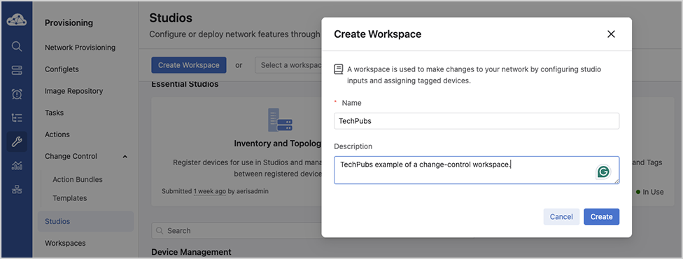
Getting Started
MSS brings microperimeter segmentation and enforcement to CloudVision. Use new tools like the MSS Studio, Policy Manager, Policy Monitor, and Policy Builder to create groups used to define microperimeters and configure security policy rules that govern how traffic is forwarded among groups.
This end-to-end guide will help you get the most out of CloudVision’s MSS functionality. You’ll begin by onboarding EOS devices with MSS capability and the ZTX Traffic Mapper monitor node, then use the MSS Studio to define static groups and policy rules. Next, onboard data sources for dynamic group discovery and review and accept groups in the Policy Manager for use in policy building. Finally, configure a monitoring rule in the MSS Studio to enable you to generate and accept policy recommendations in the Policy Builder.
Requirements
To deploy MSS a combination of the following hardware is required:
- TOR Switches
- CCS-720XP, CCS-720D, CCS-722XPM
- DCS-7010TX
- DCS-7050X3
- DCS-7280R3/R3A
- ZTX Traffic Mapper Appliances
- ZTX-7230S
- ZTX-7250S
- vZTX Appliance
Management and Visibility
- CVP or CVaaS for management and visibility.
- CVP (with MSS Manager)
Configuration
TOR Configuration
Perform the following configuration steps to prepare the devices for MSS using the CLI. Several configuration steps are required on all supported platforms, while others are unique to specific SKUs.
Refer to the specific Strata and Sand sections for SKU-specific configuration information.
Common Configurations for Sand and Strata
For the devices to be able to stream to CVP and receive information from CVP, enable gRPC Network Management Interface (gNMI) on the devices:
ld459.12:57:58(config)# management api gnmi
ld459.12:58:13(config-mgmt-api-gnmi)# transport grpc default
ld459.12:58:20(config-gnmi-transport-default)# no shutdown
If the management is in a user-defined vrf, for example vrf mgmt tenable gNMI in that user-defined vrf.
ld459.12:59:16(config)# management api gnmi
ld459.12:59:18(config-mgmt-api-gnmi)# transport grpc default
ld459.12:59:25(config-gnmi-transport-default)# vrf mgmt
ld459.12:59:40(config-gnmi-transport-default)# no shutdown
For devices to receive dynamic group information from CVP, enter the following parameters at the end ofthe TerminAttr configuration:
ld459.13:00:28(config)# daemon TerminAttr
ld459.13:00:29(config-daemon-TerminAttr)# exec /usr/bin/TerminAttr -smashexcludes=ale,flexCounter,hardware,
kni,pulse,strata -cvaddr=10.248.18.240:9910,10.248.18.241:9910,10.248.18.242:9910 -cvauth=token,/tmp/token
-cvvrf=default -taillogs -cvtargetconfigs arista/traffic-policy
! New daemon configuration will only take effect after restarting the daemon by doing 'shutdown/no shutdown'.
ld459.13:00:39(config-daemon-TerminAttr)# no shutdown
Traffic Policy Configuration
As part of enforcing MSS policies, CloudVision configures the traffic policy rules for individual EOS devices.
If required, refer to the Arista EOS System Configuration Guide for more information on traffic policies.
Strata Platform Configuration
Perform the following configuration steps to prepare the devices for MSS using the CLI. Several unique configuration steps are required on the Strata platform. These apply to:
- DCS-7050X3
- CCS-720DP (excluding 720DP-24S)
- CCD-720DT (excluding 720DT-24S)
- CCS-720DF
- CCS-720XP (excluding 720XP-96ZC2, 720XP-48TXH-2C-S)
- CCS-722XPM (excluding 722XPM-48ZY8)
- DCS-7010TX
Refer to the specific Strata and Sand sections for detailed information.
On Strata devices (7050S, 720S, and 722S platforms) add the following configuration to enable MSS:
ld459.13:02:20(config)# traffic-policies
ld459.13:04:57(config-traffic-policies)# transforms interface prefix common source-destination
Sand Platform Configuration
Perform the following configuration steps to prepare the devices for MSS using the CLI. Several unique configuration steps are required on a Sand platform. These apply to:
- DCS-7280R3/R3A (except 7280SR3-40YC6, 7280SR3E-40YC6 and 7280TR3-40C6)
Refer to the specific Strata and Sand sections for detailed information.
On Sand devices (7280R3 platforms), use the MSS Base Profile. The base profile supports:
- L4-Port Transforms: Allows the configuration of L4-port-based match rules.
- Self-IP Support: Allows the configuration of a self-IP-based rule if the policy contains
deny any anyat the end to save Control Plane packets from hitting thisdeny any anyrule. - Mirror Action: Allows the creation ofMonitor sessions to achieve ZTX monitoring node functionality.
Configuring the TCAM Profile
TCAM profiles should follow a specific flow and order, addressing required features, key fields, and important actions, as follows:
Required Features
feature traffic-policy port ipv4feature traffic-policy port ipv6feature traffic-policy vlan-interface ipv4feature traffic-policy vlan-interface ipv6
Important Key Fields
dst-portdst-ip-labelsrc-ip-labelip-protocoll4-dst-port-labell4-src-port-labelvxlan-decapsulated
Important Actions
countdropmirrorredirect
log (not MSS use case), remove the redirect/mirror action and add the log action.The feature traffic-policy port ipv4 and the feature
traffic-policy port ipv6 commands define the IPv4 and IPv6 traffic-policy lookups, respectively.
In the profile example shown below, key fields include dst-ip-label, src-ip-label, dst-ipv6-label, and src-ipv6-label. This means that the hardware is specifically programmed to first do a lookup on the destination and source IP addresses to generate a label that is then used in a subsequent stage in the rules TCAM lookup.Similarly, the key field contains l4-src-port-label and l4-dst-port-label, which means that there is a hardware lookup to transform the traffic’s L4 source and destination ports into labels that are then used in the rules TCAM lookup. Since the L4 source and destination port lookups consume a TCAM bank each, changing a profile will result in using two extra banks for the port transform tables. However, depending on the actual traffic policy, this might result in lower TCAM utilization for the rules TCAM lookup. The system must analyze the actual utilization of the TCAM banks for a given TCAM profile and its traffic-policy configuration before choosing the TCAM profile configuration.
As a reference and an example, TCAM profiles are supported on the 7280R3 platform, as shown in the configuration snippet below.
If you are using another platform, refer to that specific platform's configuration documentation.
lyv571.13:02:41(config)# hardware tcam lyv571.13:02:48(config-tcam)# profile mss-traffic-policy-l4-xform lyv571.13:02:51(config-tcam-profile-mss-traffic-policy-l4-xform)#
For MSS deployments, configure the TCAM features as shown in the MSS Base Profile example below.
MSS Base Profile
Base TCAM Profile on the 7280R3 platform:
hardware tcam
profile mss-traffic-policy-l4-xform
feature acl port mac
sequence 55
key size limit 160
key field dst-mac ether-type src-mac
action count drop mirror
packet ipv4 forwarding bridged
packet ipv4 forwarding routed
packet ipv4 forwarding routed multicast
packet ipv4 mpls ipv4 forwarding mpls decap
packet ipv4 mpls ipv6 forwarding mpls decap
packet ipv4 non-vxlan forwarding routed decap
packet ipv4 vxlan forwarding bridged decap
packet ipv6 forwarding bridged
packet ipv6 forwarding routed
packet ipv6 forwarding routed decap
packet ipv6 forwarding routed multicast
packet ipv6 ipv6 forwarding routed decap
packet mpls forwarding bridged decap
packet mpls ipv4 forwarding mpls
packet mpls ipv6 forwarding mpls
packet mpls non-ip forwarding mpls
packet non-ip forwarding bridged
feature forwarding-destination mpls
sequence 100
feature mirror ip
sequence 80
key size limit 160
key field dscp dst-ip ip-frag ip-protocol l4-dst-port l4-ops l4-src-port src-ip tcp-control
action count mirror set-policer
packet ipv4 forwarding bridged
packet ipv4 forwarding routed
packet ipv4 forwarding routed multicast
packet ipv4 non-vxlan forwarding routed decap
feature mpls
sequence 5
key size limit 160
action drop redirect set-ecn
packet ipv4 mpls ipv4 forwarding mpls decap
packet ipv4 mpls ipv6 forwarding mpls decap
packet mpls ipv4 forwarding mpls
packet mpls ipv6 forwarding mpls
packet mpls non-ip forwarding mpls
feature mpls pop ingress
sequence 90
feature qos ip
sequence 75
key size limit 160
key field dscp dst-ip ip-frag ip-protocol l4-dst-port l4-ops l4-src-port src-ip tcp-control
action set-dscp set-policer set-tc
packet ipv4 forwarding routed
packet ipv4 forwarding routed multicast
packet ipv4 mpls ipv4 forwarding mpls decap
packet ipv4 mpls ipv6 forwarding mpls decap
packet ipv4 non-vxlan forwarding routed decap
feature qos ipv6
sequence 70
key field dst-ipv6 ipv6-next-header ipv6-traffic-class l4-dst-port l4-src-port src-ipv6-high src-ipv6-low
action set-dscp set-policer set-tc
packet ipv6 forwarding routed
feature traffic-policy port ipv4
sequence 45
key size limit 160
key field dst-ip-label dst-port icmp-type-code ip-frag ip-length ip-protocol l4-dst-port-label l4-src-port-label src-ip-label tcp-control ttl vxlan-decapsulated
action count drop mirror redirect
packet ipv4 forwarding bridged
packet ipv4 forwarding routed
packet ipv4 mpls ipv4 forwarding mpls decap
packet ipv4 non-vxlan forwarding routed decap
packet ipv4 vxlan eth ipv4 forwarding bridged decap
packet ipv4 vxlan eth ipv4 forwarding routed decap
packet mpls ipv4 forwarding bridged
packet mpls ipv4 forwarding mpls
feature traffic-policy port ipv4 egress
key size limit 160
key field dscp dst-ip-label ip-frag ip-protocol l4-dst-port l4-src-port src-ip-label tcp-control
action count drop log
packet ipv4 forwarding routed
packet mpls ipv4 forwarding mpls
feature
traffic-policy port ipv6
key field dst-ipv6-label hop-limit ipv6-length ipv6-next-header ipv6-traffic-class l4-dst-port l4-dst-port-label l4-src-port l4-src-port-label src-ipv6-label tcp-control
action count drop mirror redirect
packet ipv6 forwarding bridged
packet ipv6 forwarding routed
packet mpls ipv6 forwarding bridged
packet mpls ipv6 forwarding mpls
packet mpls ipv6 forwarding routed decap
feature traffic-policy port ipv6 egress
key field dscp dst-ipv6-label ipv6-next-header l4-dst-port l4-src-port src-ipv6-label tcp-control
action count drop log
packet ipv6 forwarding routed
packet mpls ipv6 forwarding mpls
feature traffic-policy vlan-interface ipv4
key size limit 160
key field dst-ip-label dst-port icmp-type-code ip-frag ip-length ip-protocol l4-dst-port-label l4-src-port-label src-ip-label tcp-control traffic-policy-override-label ttl vxlan-decapsulated
action count drop mirror redirect
packet ipv4 forwarding bridged
packet ipv4 forwarding routed
packet ipv4 vxlan eth ipv4
forwarding bridged decap
packet ipv4 vxlan eth ipv4 forwarding routed decap
feature traffic-policy vlan-interface ipv6
key size limit 160
key field dst-ipv6-label hop-limit ipv6-length ipv6-next-header ipv6-traffic-class l4-dst-port l4-dst-port-label l4-src-port l4-src-port-label src-ipv6-label tcp-control traffic-policy-override-label vxlan-decapsulated
action count drop mirror redirect
packet ipv4 vxlan eth ipv6 forwarding routed decap
packet ipv6 forwarding routed
packet ipv6 vxlan eth ipv6 forwarding routed decap
feature tunnel vxlan routing
sequence 10
packet ipv4 forwarding routed
packet ipv4 non-vxlan forwarding routed decap
packet ipv4 vxlan eth ipv4 forwarding routed decap
packet ipv4 vxlan eth ipv6 forwarding routed decap
traffic-policy-override-label in the vlan-interface traffic policy feature is supported starting from EOS version 4.35.1F. For more details see: https://www.arista.com/en/support/toi/eos-4-24-2f/14550-support-for-traffic-policy-on-interfaces#tcam-profile-requirements-for-interface-overridepacket ipv4 vxlan eth ipv4
forwarding bridged decap is supported starting from EOS version 4.35.1F. For more details see: https://www.arista.com/en/support/toi/eos-4-24-2f/14550-support-for-traffic-policy-on-interfaces#decapsulated-vxlan-packet-matchingZTX Traffic Mapper Configuration Examples
This chapter provides several configuration examples that can be used to implement both out-of-band and in-band communication requirements for the ZTX Traffic Mapper.
Out-of-band Configuration Prerequisites
As a prerequisite, the ZTX Traffic Mapper requires an IP address assigned to its management interface and an active Streaming Agent (TerminAttr) instance, in order to communicate with CloudVision. Refer to the documentation to learn about the different options for onboarding an Arista device in CloudVision.
This example assumes that:
-
The CloudVision cluster uses the following IP addresses: 172.28.137.75, 172.28.130.47, 172.28.133.90
-
The ZTX Traffic Mapper device is provisioned with at least one valid NTP server and with the proper clock time zone, for example:
ntp server my-ntp-server.mydomain.mycompany.com
!
clock timezone US/Pacific
!
-
The ZTX Traffic Mapper device is provisioned with a management address of 172.28.137.229/20 and a default gateway in the default VRF:
interface Management1/1
ip address 172.28.137.229/20
!
ip route 0.0.0.0/0 172.28.128.1
In-band Configuration - MLAG Peering and Static Routing
These are in summary the configuration steps for this example:
- A single port channel is provisioned on both the ZTX Traffic Mapper and MLAG pair.
- The ZTX Traffic Mapper is configured with a unique IP address in a specific subnet that is assigned to an SVI.
- The VLAN used by this SVI is configured on the port channel on both the ZTX Traffic Mapper and the MLAG pair.
- The same IP subnet is assigned to the corresponding SVI on the MLAG pair.
- The ZTX Traffic Mapper is configured with a static route in order to have reachability to the switches in the Security Domain.
- The MLAG pair communicates with the rest of the IP network with a dynamic protocol of choice and advertises the local subnet of the SVI to provide reachability to the ZTX Traffic Mapper IP address.
- The ARP timeout of the ZTX Traffic Mapper is tuned to achieve peer adjacency persistence.
- A single port channel is provisioned on both the ZTX Traffic Mapper and MLAG pair.
On the ZTX Traffic Mapper:
interface Port-Channel16
!
interface Ethernet1/1 - Ethernet1/16
channel-group 16 mode active
!
On MLAG left and right switches:
interface Port-Channel8
mlag 8
!
interface Ethernet11/1 - 4
speed forced 10000full
channel-group 8 mode active
!
interface Ethernet13/1 - 4
speed forced 10000full
channel-group 8 mode active
!
- The ZTX Traffic Mapper is configured with a unique IP address in a specific subnet that is assigned to an SVI.
vlan 1016
!
interface vlan1016
ip address 10.10.16.4/29
!
- The VLAN used by this SVI is configured on the port channel on both the ZTX Traffic Mapper and the MLAG pair.
On the ZTX Traffic Mapper:
interface Port-Channel16
switchport access vlan 1016
!
On the MLAG switch pair:
vlan 1016
!
interface Port-Channel8
switchport access vlan 1016
!
- The same IP subnet is assigned to the corresponding SVI on the MLAG pair.
On both left and right switch:
interface vlan1016
ip virtual address 10.10.16.1/29
!
- The ZTX Traffic Mapper is configured with a static route in order to have reachability to the switches in the Security Domain.
Assuming these switches use addresses taken from a 10.10.0.0/19 aggregate subnet:
ip routing
!
ip route 10.0.0.0/19 10.10.16.1
- The MLAG pair communicates with the rest of the IP network with a dynamic protocol of choice and advertises the locally connected subnet of the SVI to provide reachability to the ZTX Traffic Mapper IP address.
For example, using OSPF:
router ospf 10
redistribute connected
!
- The ARP timeout of the ZTX Traffic Mapper is tuned to achieve peer adjacency persistence This step is recommended with static routing and ensures that the layer-2 adjacency does not expire in case monitoring is inactive and peer links are idle.
arp aging timeout default 180
In-band Configuration - Dynamic Routing
These are in summary the configuration steps for this example:
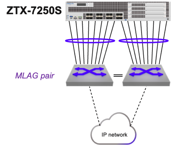
- A single routed port channel is provisioned on the ZTX Traffic Mapper and each peering switch, and configured with a point-to-point subnet.
- The ZTX Traffic Mapper is configured with a unique host IP address that is assigned to a loopback interface.
- The ZTX Traffic Mapper is configured with a dynamic routing protocol and peering with the adjacent switches, in order to have mutual reachability between its loopback address and those assigned to the switches in the Security Domain.
The following are the configuration step details:
- A single routed port channel is provisioned on the ZTX Traffic Mapper and each peering switch, and configured with a point-to-point subnet.
interface Port-Channel8
no switchport
ip address 192.168.100.101/31
!
interface Ethernet1/1 - Ethernet1/8
channel-group 8 mode active
!
interface Port-Channel16
no switchport
ip address 192.168.100.103/31
!
interface Ethernet1/9 - Ethernet1/16
channel-group 16 mode active
!
On left peering switch:
interface Port-Channel8
no switchport
ip address 192.168.100.100/31
!
interface Ethernet11/1 - 4
speed forced 10000full
channel-group 8 mode active
!
interface Ethernet13/1 - 4
speed forced 10000full
channel-group 8 mode active
!
On right peering switch:
interface Port-Channel16
no switchport
ip address 192.168.100.102/31
!
interface Ethernet11/1 - 4
speed forced 10000full
channel-group 16 mode active
!
interface Ethernet13/1 - 4
speed forced 10000full
channel-group 16 mode active
!
- The ZTX Traffic Mapper is configured with a unique host IP address that is assigned to a loopback interface.
interface Loopback0
description router-id
ip address 10.135.2.16/32
!
- The ZTX Traffic Mapper is configured with a dynamic routing protocol, in this example BGP, and peering with the adjacent switches, in order to have mutual reachability between its loopback address and those assigned to the switches in the Security Domain.
On the ZTX Traffic Mapper:
router bgp 64516
router-id 10.135.2.16
distance bgp 20 200 200
maximum-paths 2
neighbor UNDERLAY peer group
neighbor UNDERLAY maximum-routes 120
neighbor 192.168.100.100 peer group UNDERLAY
neighbor 192.168.100.100 remote-as 64504
neighbor 192.168.100.100 description SwitchLeft
neighbor 192.168.100.102 peer group UNDERLAY
neighbor 192.168.100.102 remote-as 64504
neighbor 192.168.100.102 description SwitchRight
redistribute connected
!
address-family ipv4
neighbor UNDERLAY activate
!
On left peering switch:
router bgp 64504
network 10.135.2.0/24
neighbor ZTX peer group
neighbor ZTX route-map LOOPBACKS out
neighbor 192.168.100.101 peer group ZTX
neighbor 192.168.100.101 remote-as 64516
neighbor 192.168.100.101 description ZTX-1
!
address-family ipv4
neighbor ZTX activate
!
route-map LOOPBACKS permit 10
match ip address prefix-list LOOPBACKS
!
ip prefix-list LOOPBACKS seq 5 permit 10.135.2.0/24
!
On right peering switch:
router bgp 64504
network 10.135.2.0/24
neighbor ZTX peer group
neighbor ZTX peer group
neighbor ZTX route-map LOOPBACKS out
neighbor 192.168.100.103 peer group ZTX
neighbor 192.168.100.103 remote-as 64516
neighbor 192.168.100.103 description ZTX-1
!
address-family ipv4
neighbor ZTX activate
!
route-map LOOPBACKS permit 10
match ip address prefix-list LOOPBACKS
!
ip prefix-list LOOPBACKS seq 5 permit 10.135.2.0/24
!
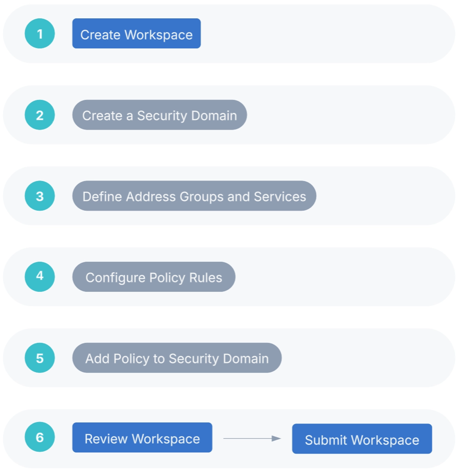
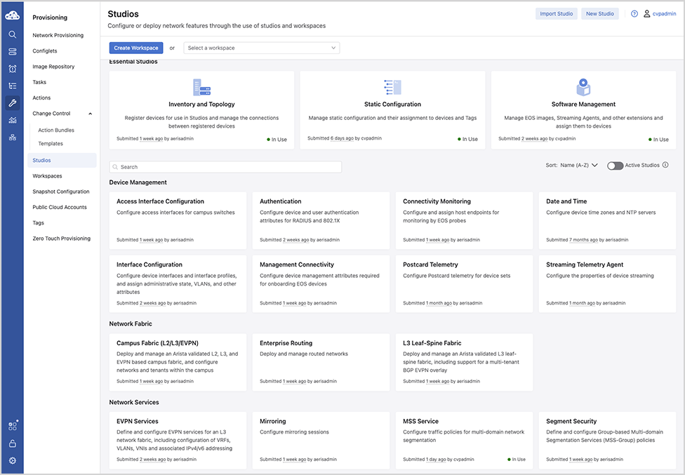
CloudVision Workflow
CloudVision Portal (CVP) is your turnkey solution for managing, monitoring, and maintaining your network devices. Once you have onboarded your switches in CVP review the following steps and procedures.
Use following the QR Code or the links to locate the relevant CVP sections providing detailed configuration information.

CVP Documentation Link - https://www.arista.io/help/articles/b3ZlcnZpZXcubXNzLmdldHRpbmdTdGFydGVk
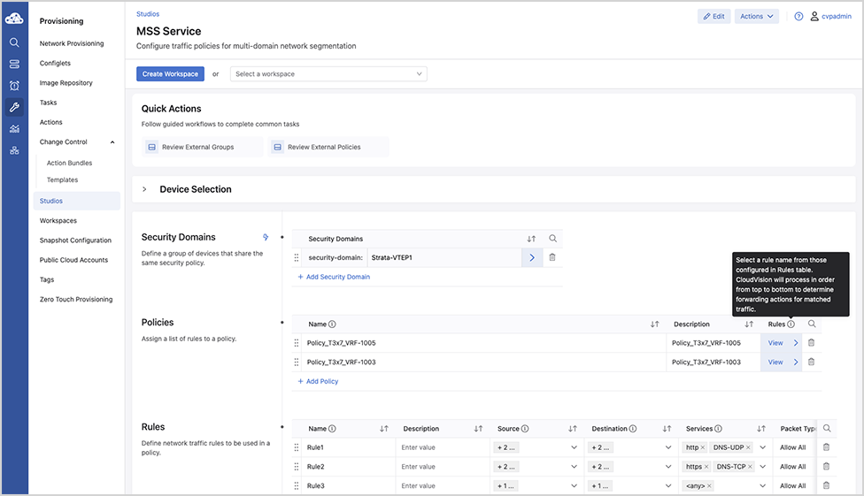
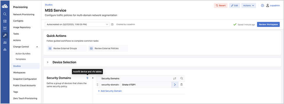
Security Domains - Under Security Domains, select Add Security Domain and enter a title for the domain.
Onboarding a Data Source - A data source is a third-party device or management system that streams data to CloudVision. The required configuration is managed in CloudVision.
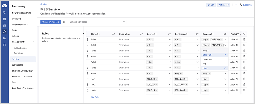
Create Policies - Static and Dynamic - Under Policies, select Add Policy and enter a policy name and then apply the policy on the security domain VRF.
Onboard Devices
- Onboard the 7280R3 and 7050X3/720/722-series devices and the ZTX Traffic Mapper monitor appliance.
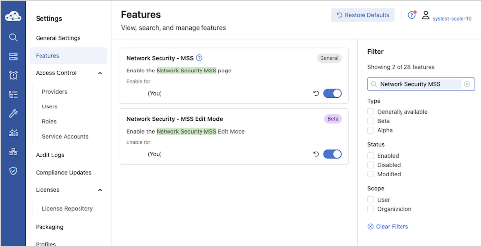
Note: If the End-to-End Provisioning toggle is enabled in General Settings, newly-onboarded devices will automatically be available to be registered for use in Studios.
- Register devices in Studios
Once you’ve onboarded relevant EOS devices, you’ll register them in the Inventory and Topology Studio for use in Studios.
- Navigate to the Inventory and Topology Studio and click Network Updates.
- Enable the checkbox next to the onboarded device or devices and click Accept Updates.
You will now be able to use these devices in the MSS Studio where you will configure static security domain groups and security policy rules.
Reconciling Device Configuration
Building the workspace will detect if any device configuration is non-compliant and needs to be reconciled.
- Select Reconcile.
Figure 6. Reconcile Tab 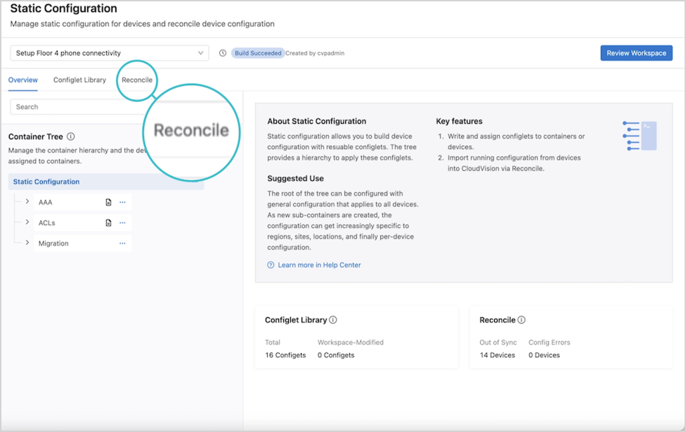 Devices detected with non-compliant running configuration will be displayed.
 - Select Start Build.
Figure 7. Start Build 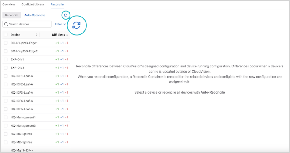 This will update the list of devices that are out of compliance.
 - Select one or more devices.
Figure 8. Select Devices 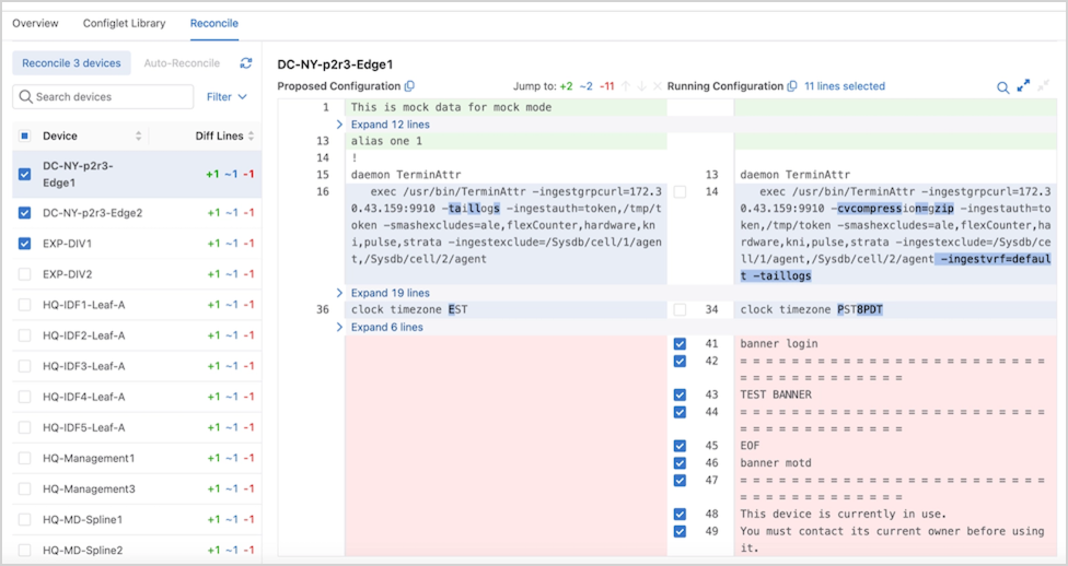 Choose the lines from the running configuration to include or overwrite the designed configuration using the checkboxes.Tip: Select Auto-Reconcile to reconcile all devices with one action.
 - Select Reconcile.
Figure 9. Reconcile Multiple Devices 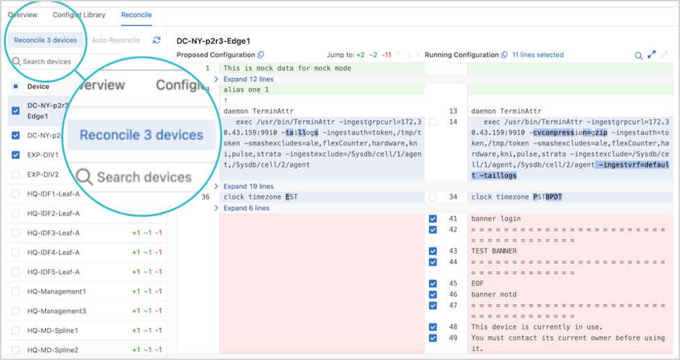
The workspace is rebuilt, and a new container in the Container Tree called Reconciled Configlets is displayed.
Figure 10. Configlets 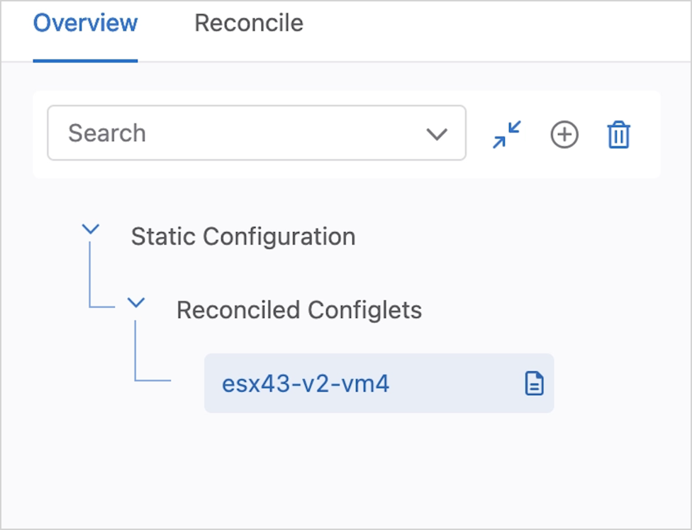 The order of configuration is important. Ensure that the reconciled configuration follows the established EOS hierarchy both within the configlet and in the order of containers.
Installing the ZTX Traffic Mapper Appliance
For Installation and Configuration of the MSS ZTX Traffic Mapper (Monitor Node appliance), refer to the Quick Start Guide on the Arista documentation page.
Deploying the ZTX Traffic Mapper Workflow
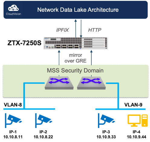
- CVP configures mirroring: CVP installs MSS rules on the ingress TORs to mirror traffic from selected network VRFs or network devices towards the ZTX Traffic Mapper node.
- ITORs mirror traffic to the ZTX Traffic Mapper node: Once the mirroring configuration is active, selected traffic is mirrored from the ingress TOR via a GRE tunnel to the ZTX Traffic Mapper node.
- ZTX Traffic Mapper node summarizes session: Upon receiving mirrored traffic from the ingress TORs, the ZTX Traffic Mapper node tracks and aggregates sessions bidirectionally.
- ZTX Traffic Mapper node exports summarized sessions to CVP: The ZTX Traffic Mapper node exports the summarized session information to CVP
- CVP associates summarized session data with metadata to suggest a policy that the user can then review and modify.
- CVP suggests a permit action to create MSS rules based on these summarized session records. However, upon review, the policy action can be modified and pushed to the ITOR switches, enforcing the rules.
Configuration
The ZTX Traffic Mapper appliance is managed primarily through CloudVision’s MSS Service Studio once the device has been onboarded and bootstrapped with configuration pushed through the Static Configuration Studio. Device onboarding is described by the following Device Onboarding instructions. Since MSS Service will manage the device at runtime, this configuration section will primarily focus on the necessary bootstrap configuration that is pushed through Static Configlets Studio. Configuration pushed through MSS Service can also be validated.
Static Configuration Studio
Static Configuration Studio can be leveraged to build the initial configurations on the ZTX Traffic Mapper node and include provisioning loopback, Ethernet and port-channel interface and IP connectivity to other devices in the network. Additional details about Static Configlet Studios are available on the Arista CloudVision Help Center Static Configuration Studio site.
Ports from the ZTX Traffic Mapper device used as uplinks to the MLAG Service TOR should all be members of a single port-channel to achieve maximum throughput with the service TOR. A loopback interface is needed to act as the GRE tunnel endpoint to terminate mirrored packets. The following is a sample configuration that can be pushed from Static Configuration Studio to bootstrap the device so that it can be managed by MSS Service.
ZTX# show running-config
!
! Port-Channel with member ports connected to MLAG Service TOR.
! MLAG service TOR peers should have an IP address in the same network
interface Port-Channel1
no switchport
ip address 10.10.250.1/24
!
interface Ethernet1/1
speed forced 10000full
no switchport
channel-group 1 mode active
!
interface Ethernet1/2
speed forced 10000full
no switchport
channel-group 1 mode active
!
! Loopback Interface used as GRE tunnel endpoint.
interface Loopback0
ip address 10.10.254.1/32
!
! Default static route for reachability of GRE mirror source
ip route 0.0.0.0/0 10.10.250.2
CloudVision MSS Service
Use the MSS Service to configure the ZTX Traffic Mapper device and the mirroring session on the MSS TOR. The following section describes the configuration that MSS Service will push and how the configurations contribute to the overall solution. Aside from using show commands for debugging, the user is not expected to actively manage the ZTX Traffic Mapper device after the onboarding and bootstrap stage are complete.
The following configuration puts the ZTX Traffic Mapper device into monitor mode.
ZTX# show running-config
!
firewall distributed instance
mode monitor
no disabled
!
The following configuration exports the flows observed by the monitoring device to CV using IPFIX as the transport. Note that TA is acting as IPFIX collector listening on 127.0.0.1 for IPFIX records and then streaming that data to CV for ingest to provide telemetry and policy recommendations.
ZTX# show running-config
!
flow tracking firewall distributed
tracker flowtrkr
exporter exp
collector 127.0.0.1
local interface Loopback0
no shutdown
!
Tunnels are configured to terminate each GRE tunnel created from a TOR’s monitor sessions, and flow tracker is enabled on all the tunnels. The tunnel source is always set to the IP address of the loopback interface created during the bootstrap process. The tunnel destination corresponds to the GRE tunnel endpoint of the TOR that originated the mirror session. Note that the mirrored traffic is terminated at the ZTX Traffic Mapper device and is always dropped, so the reverse GRE tunnel is never utilized.
ZTX# show running-config
!
interface Tunnel0
flow tracker firewall distributed flowtrkr
tunnel mode gre
tunnel source 10.10.254.1
tunnel destination 10.10.254.2
!
ZTX Traffic Mapper Software Deployment
Deploying the ZTX Traffic Mapper
Deploying the ZTX Traffic Mapper (monitor node) in an Arista Network
This chapter describes how the ZTX Traffic Mapper can be physically and logically inserted in an Arista network and provides reference configuration examples.
IP Communication Requirements
 |
|
In-band Connectivity Requirements
The ZTX Traffic Mapper throughput is used for extracting and exporting communication session metadata from mirrored traffic received by the switches that compose one (and only one) Security Domain. The traffic received by the ZTX Traffic Mapper consists of a copy (mirror) of the original layer-2 traffic packets that match one or more monitor rules, truncated to the first 256 or 192 bytes1 and embedded into an L2GRE envelope, which adds 24 bytes of overhead.
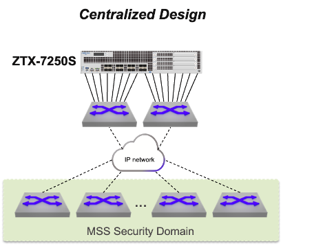
- Centralized: The ZTX Traffic Mapper is placed within a service pod and its interfaces are physically connected to a pair of switches that have IP connectivity to the Security Domain.
This option is based on the best practice of using a dedicated self-contained unit in the network to provide all required network services with optimal scalability, efficiency, and simplicity.
With this approach, the planned network throughput of the service pod needs to account for the theoretical inbound capacity of the ZTX Traffic Mapper, unless further rate limiters are applied in the data path from the Security Domain.
The physical links of the ZTX Traffic Mapper that connect to the same physical device or, in case the peer devices use multi-chassis link aggregation, to the same device pair, can be grouped in a port channel. This choice may also depend on the selected routing design, which is discussed next.
IP Routing Requirements
To satisfy its in-band communication requirements, the ZTX Traffic Mapper must be provisioned with a distinct IP address, which needs to be reachable by the switches part of the Security Domain in order to create L2GRE tunnels that use the ZTX Traffic Mapper address as the destination. The IP address of the ZTX Traffic Mapper can be advertised to the adjacent switches via dynamic routing, or the adjacent switches can be configured with a specific static route that the adjacent switches can redistribute in their current routing protocol.
From an outbound routing direction perspective, the ZTX Traffic Mapper requires in its routing table either every loopback address of the switches of the Security Domain or an aggregate prefix that includes them. This information is needed for the sole purpose of a GRE tunnel health check, and can also be provided via dynamic or static routing.
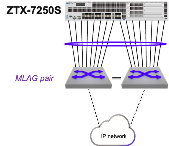
In case the ZTX Traffic Mapper is physically adjacent to a pair of switches that support MLAG, the choice of using dynamic vs. static routing influences the decision on how to bundle the ZTX Traffic Mapper interfaces into one or two port channels.
VRF and Security Zone Awareness
Monitoring rules are elements of MSS policies, configured on the Security Domain switches, which apply to a specific VRF, representing a determined security zone. On the ZTX Traffic Mapper, the VRF is identified via a GRE keyword field, present in the mirrored packet, and does not need to be declared in the device configuration.
L2GRE Tunnel Provisioning
The provisioning of L2GRE tunnels on the ZTX Traffic Mapper and the Security Domain switches is automatic and triggered by creating or modifying monitoring rules and other MSS objects in CloudVision.
Managing the ZTX Traffic Mapper with CloudVision
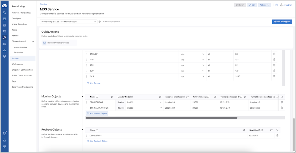
Once the ZTX Traffic Mapper device has been onboarded to CloudVision and the in-band communication with the Security Domain is complete, the next step is to associate it with an MSS Monitor Object in CloudVision, so it can be referenced by one or more policy rules.
An MSS Monitor Object is a structure that defines how a ZTX Traffic Mapper device can communicate with a Security Domain.
| Parameter | Description | Recommended Value |
|---|---|---|
| Name | Unique string identifying the Monitor Object that can be referenced by a policy rule | |
| Monitor Node | Associated ZTX Traffic Mapper device among those present in the device inventory | |
| Exporter Interface | Interface name on the ZTX Traffic Mapper that is used as IPFIX exporter and L2GRE tunnel termination | |
| Active Timeout | Active timeout period in ms for exporting IPFIX reports |
long-term setting: 30000 – 300000 ms
temporarily for initial deployment: 3000 - 30000 ms |
| Tunnel Destination IP | IP address of the ZTX Traffic Mapper used as L2GRE tunnel destination on switches part of the Security Domain | |
| Tunnel Source Interface | The interface name on the Security Domain switches is used as an L2GRE tunnel source.
Note: All switches consistently use the same interface name.
Important: Tunnel Source Interface IP should be unique to each TOR. In the MLAG deployment scenario, specify the Tunnel Source Interface IP unique to each MLAG peer device rather than specifying interfaces with shared IP addresses.
|
|
| Truncation | Boolean field, indicating if mirrored traffic is truncated or not | Yes |
| Rate Limit | Rate limiter expressed in Mbps applied on Security Domain switches to mirrored traffic per VRF sent to the ZTX Traffic Mapper | 10,000 |
Once a new Monitor Object entry has been populated with all required values, it is possible to select it inside the field Monitor Name in multiple policy rules part of the same policy.
The same Monitor Object can be concurrently referred to by multiple policies, while a policy (associated with a security zone) can only use one Monitor Object.
If no errors are reported, the change-control workspace can be reviewed, using Review Workspace, and subsequently executed, following the same workflow used by other studios.