Rack Mounting the Switch
The rack mounting procedure is identical for all switches covered by this guide. Illustrations in this chapter depict the mounting of a DCS-7050QX-32S switch.
Les procédure de montage du bâti est identique pour tous les commutateurs visés par ce guide. Illustrations dans ce chapitre montrent le montage d’un interrupteur de DCS-7050QX-32S.
After completing the instructions for your rack type, proceed to Cabling the Switch.
Two-Post Rack Mount
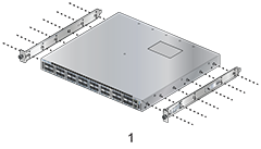
To mount the switch onto a two-post rack, assemble the mounting brackets to the chassis, then attach the brackets to the rack posts. Two-post accessory kits include the following two-post mounting parts:
2- Three-hole Mounting Brackets
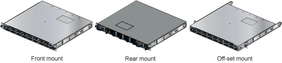
Each chassis side has attachment pins that align with bracket holes. Pin orientation is symmetric and equidistant, supporting bracket placements where the flange is flush with the front switch panel, flush with the rear panel, or not flush with either panel. Each bracket hole includes a key-opening for placing the bracket flush with the chassis and then locking it into place.
Attachment pins must engage all three upper bracket holes.
Goupilles de fixation doivent être bloquer tous les trois trous de la bride supérieure.
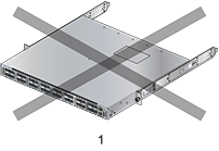
Figure 1 displays proper bracket mount configuration examples. Figure 2 displays improper bracket mount configuration examples.
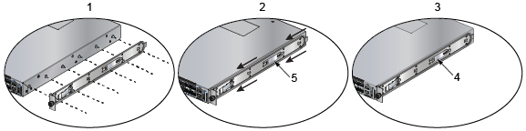
Attaching Mounting Brackets to the Chassis
- Place the bracket flush on the chassis with attachment pins protruding through key-openings.
Figure 1. Bracket Mount Examples for Two-Post Rack Mount 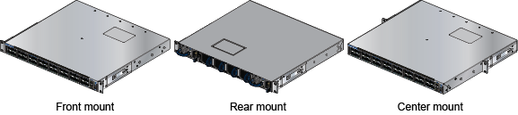
Figure 1. Improper Bracket Mount Examples for Two-Post Rack Mount 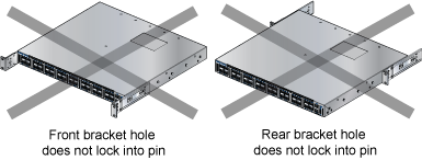
- Slide the Bracket Toward the front Flange until the bracket clip locks with an audible click.
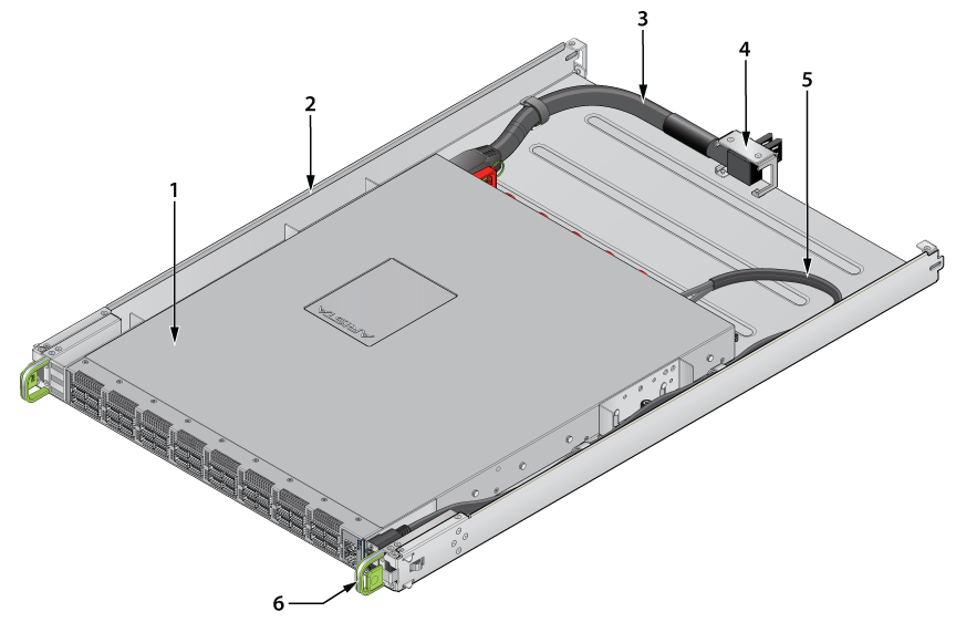
Figure 3. Attaching the Mounting Brackets to the Switch Chassis 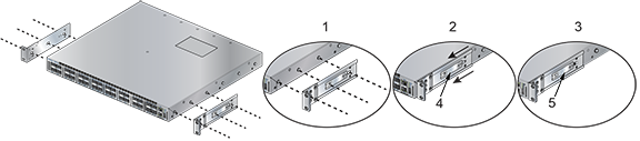
1 Step 1 2 Step 2 3 Step 3 4 Bracket clip (attached) 5 Bracket clip (aligned) Note: Deep and heavy devices could droop and cause damage to the equipment rack if front or rear-mounted. Arista recommends only center mounting for switches covered in this guide when two-post mounting is required, and the switch accessory kit includes two-post mounting ears. Four-post mounting ears differs from two-post mounting ears and should not be used for two-post mounting.To remove the mounting bracket from the chassis, lift the front edge of the mounting bracket clip with a flathead screwdriver and slide the bracket away from the front flange (opposite from the installation direction).
Inserting the Switch into the Rack
- Lift the chassis into the rack. Position the flanges against the rack posts.
- Select mounting screws that fit your equipment rack.
- Attach the bracket flanges to the rack posts.
Figure 4. Inserting the Switch into the Rack 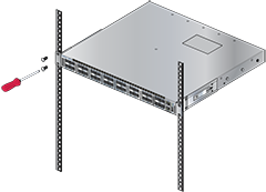
After completing the two-post rack mount, proceed to Cabling the Switch.
Four-Post Rack Mount
The switch is mounted onto a four-post rack by assembling two rails onto the rear posts, sliding the switch onto the rails, and securing the switch to the front posts.
- 2 - six-hole mounting brackets
- 2 - rail-rods
- 2 - rail-slides
The rail-rods and rail-slides assemble into two identical slide-rails.
Each chassis side has attachment pins that align with bracket holes. Pin orientation is symmetric and equidistant, supporting bracket placements where the flange is flush with the front switch panel, flush with the rear panel, or not flush with either panel. Each bracket hole includes a key-opening for placing the bracket flush with the chassis and then locking it into place.
Attachment pins must engage at least five of the six bracket holes.
Goupilles de fixation doivent être lock au moins cinq des trous du six support.
Figure 5 displays proper bracket mount configuration examples. Figure 6 displays an improper bracket mount configuration example.
| 1 | Bracket not attached by at least 5 pins |
Attaching Mounting Brackets to the Chassis
| 1 | Attaching brackets for front mount |
- Align the mounting brackets with the attachment pins to obtain the desired mounting position.
- Place the bracket flush on the chassis with attachment pins protruding through key-openings.
- Slide the bracket toward the front flange until the bracket clip locks with an audible click.
To remove the mounting bracket from the chassis, lift the front edge of the mounting bracket clip with a flathead screwdriver and slide the bracket away from the front flange (opposite from the installation direction).
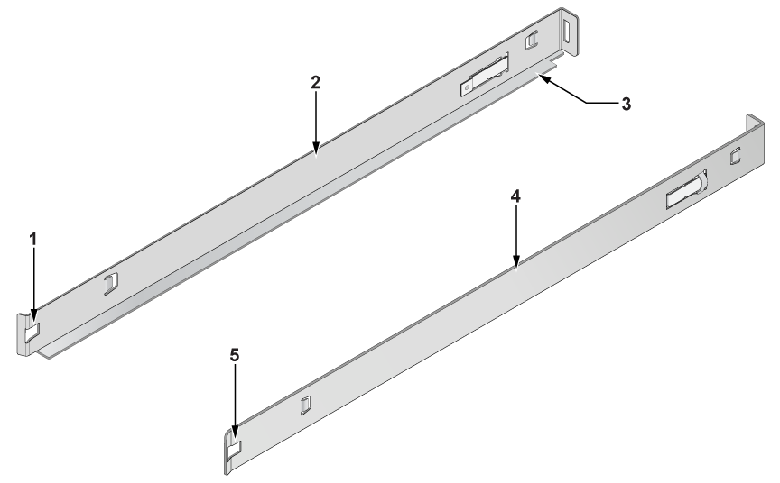
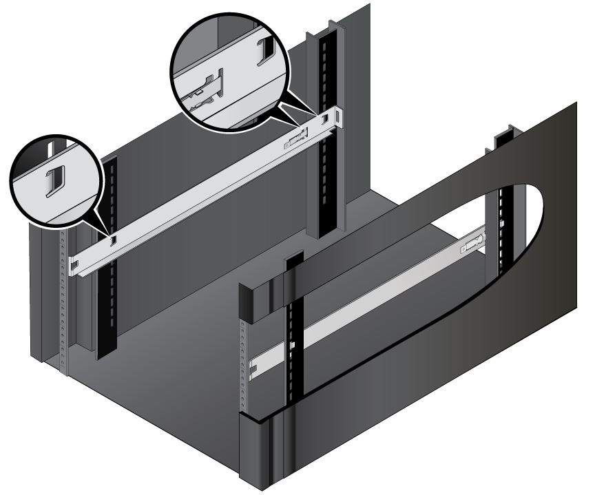
Assembling the Rails onto the Equipment Rack
Rail-rods and rail-slides assemble into two identical rails. Each rail connects a front post to a rear post. When the rails are installed, the switch slides on the rails into the rack. Each bracket includes a screw that attaches the switch to the rail.
Each end of an assembled rail contains two rack plugs (Attaching the Mounting Brackets to the Switch Chassis). The rails are installed into a rack by inserting the plugs into rack slots. When installing rails into posts with threaded or rounded holes, remove all plugs located on both sides of the assembled rails, then install the rails with bolts that fit the rack.
| 1 | Step 1 | 2 | Step 2 | 3 | Step 3 |
| 4 | Bracket clip (attached) | 5 | Bracket clip (aligned) |
- Slide a rail-rod into a rail-slide (Figure 9) until the rail clip makes an audible click.
The rail clip prevents the extension of the rail beyond the maximum supported distance between the front and rear rack posts.
Figure 9. Assembling the Rails 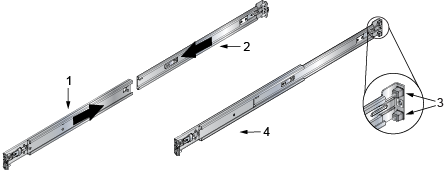
1 Rail-slide 3 Rack plugs 2 Rail-rod 4 Rail (assembled) - Attach the rail to the right rear rack post by inserting rod-end rack plugs into post slots (Attaching the Rails - Inset A). The slide assembly must be inside the right posts relative to the left rack posts.
If the rack plugs were previously removed, use bolts to attach the rail to the rack.
- Attach the slide end of the rail to the front post by extending the rail end past the post, then contracting the rail while guiding the rack plugs into the post (Attaching the Rails - Inset B).
- Repeat Step 1 through 3 for the left posts. Ensure the rails are on the same horizontal level.
Figure 10. Attaching the Rails 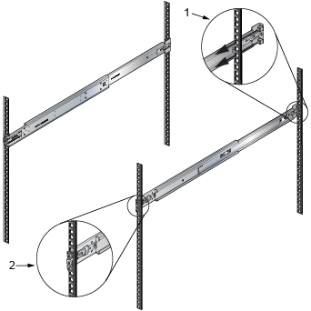
1 Inset A 2 Inset B
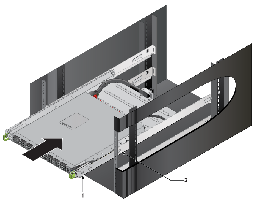
Attaching the Switch to the Rack
- Lift the switch into the rack and insert the mounting brackets into the slide rails(Figure 11).
Figure 11. Inserting the Switch onto the Rails 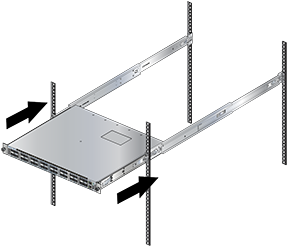
- Slide the switch on the rails toward the rear posts until the mounting bracket flanges are flush with the rail flanges attached to the rack posts.
- Attach the bracket flanges to the rack post using the quick-release thumb screws supplied with the brackets (Figure 12).
Figure 12. Attaching the Switch to the Rack Posts 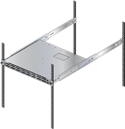
After completing the four-post rack mount, proceed to Cabling the Switch.
DC-powered Rack Mount
There are ordering options for the switch that enable mounting in DC-powered racks such as ORv3 and its variants.
The following sections describe mounting the appropriate switch SKU in the relevant DC-powered rack. In all cases, installation requires mounting rails to be attached to the rack followed by inserting and securing the switch assembly to the rack.
ORv3 Rack Mount
The following figure shows the DCS-7060DX4-32C-RV3-F designed to be mounted in ORv3 racks.
.
| 1 | Switch | 3 | Power cable (DC) | 5 | Management port cables |
| 2 | Left side of switch assembly | 4 | DC power connector | 6 | Handle and latch release |
| 1 | Hole (for latching) | 3 | Shelf (for switch assembly) | 5 | Hole (for latching) |
| 2 | L-shaped, IT-support bracket | 4 | L-shaped, IT-support bracket |
Racking the Switch Assembly (ORv3 Rack)
Perform the following tasks to mount the switch assembly into an ORv3 rack.
- Attach the L-shaped, IT-support bracket (not included with switch assembly) to the rack posts where the switch assembly will be mounted .
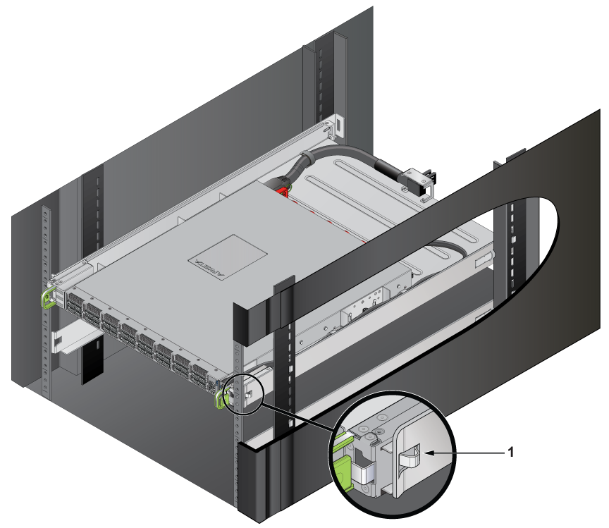
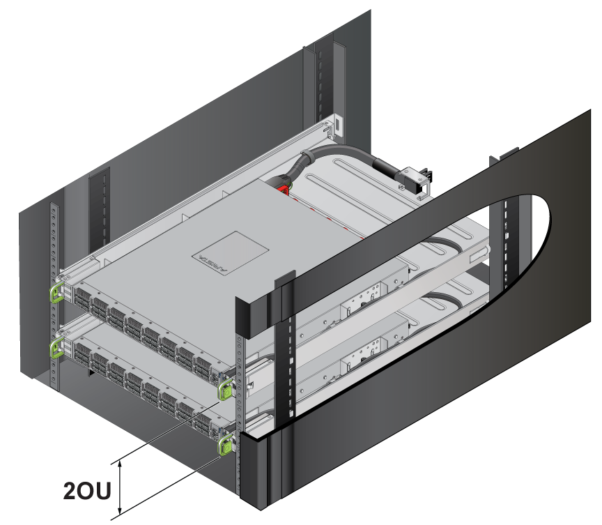
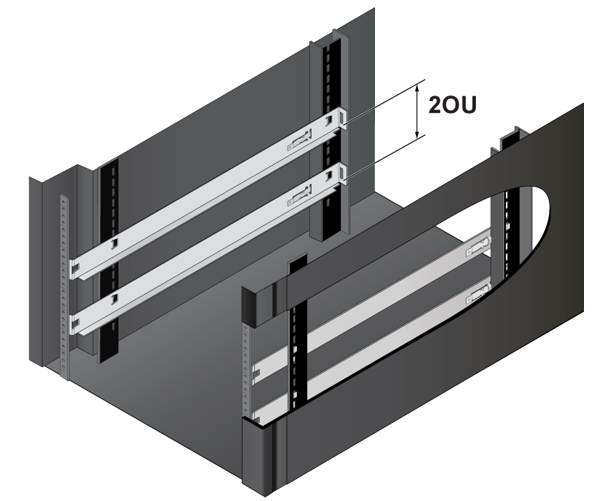
Note: Install the IT-support brackets at the same level to ensure that the switch assembly will be horizontal when racked. The IT-support brackets should snap into place on the supports. - If you are installing multiple switches, maintain a minimum of 2OU separation between them to provide space for servicing the hot-swappable fan.
- Slide the switch assembly onto the shelf formed by the IT-support brackets.
1 Latch 2 Hole for latching - Ensure that both the front latches are secured.