Rack Mounting the Switch
The accessory kit provides components for installing the switch in two-post and four-post racks.
• Section 3.1 provides instructions for mounting the switch in a two-post rack.
• Section 3.2 provides instructions for mounting the switch in a four-post rack.
The rack mounting procedure is identical for all modular switches. Illustrations in this chapter depict the mounting of an unpopulated DCS-7508 chassis.
After completing the instructions for your rack type, proceed to Chapter 4.
Two-Post Rack Mount
To mount the switch to a two-post rack, assemble mounting brackets to the middle of the chassis, then attach the brackets to the rack. The switch does not support a front or rear mount into a two-post rack.
The accessory kit includes the following two-post mounting parts:
• 2 center-mount brackets
• 20 M4x8 panhead Phillips screws
Figure B-2 displays the two-post mounting parts.
Attaching Mounting Brackets to the Chassis
Step 1 Orient the switch chassis and the two center-mount brackets (Figure 3-1).
Position the flanges that attach to the rack posts toward the rear of the chassis.
Step 2 Attach both center-mount brackets to the chassis.
Each bracket requires ten M4x8 panhead Phillips screws.
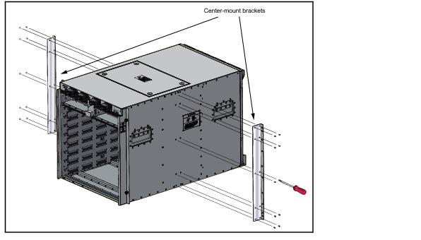
Figure 3-1: Attaching the Center-mount Brackets
Inserting the Switch into the Rack
Step 1 Move the chassis to the rack using a mechanical lift (Figure 3-2).
If modules are inserted in the chassis, use the lift carefully to avoid damaging any components.
Step 2 Lift the chassis into the rack. Position the flanges against the rack posts (Figure 3-2).
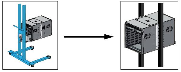
Figure 3-2: Lifting the Switch Chassis into the Two Post Rack
Step 3 Select mounting screws that fit your equipment rack.
A minimum of four screws is required on each side of the chassis. The accessory kit provides screws that fit many common equipment racks. When installing the switch into a rack with unthreaded post holes, nuts are also required to secure the switch to the rack posts.
Step 4 Attach the bracket flanges to the rack posts (Figure 3-3). Space the screws evenly along the flange.
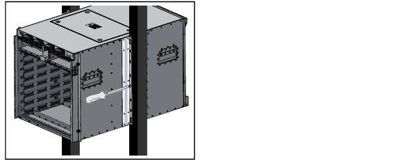
Figure 3-3: Attaching Flanges to the Rack Post
After completing the two-post installation, proceed to Chapter 4.
Four-Post Rack Mount
The switch is mounted onto a four-post rack by assembling a shelf into the rack, then placing the switch on the shelf.
The accessory kit provides the following four-post mounting parts:
• 2 front brackets
• 4 shelf supports
• 2 back brackets (not needed for racks with threaded holes)
• left shelf
• right shelf
Figure B-1 displays the four-post mounting parts.
Assembling the Shelf
Step 1 Attach the front bracket and shelf support to the left front rack post, as shown in Figure 3-4. An up arrow is printed on the shelf support to indicate its proper orientation.
Unthreaded rack holes: Use the M6 screws and cage nuts supplied in the accessory kit.
Threaded rack holes: Attach the front bracket to the post with screws that can be threaded through the rack post. Secure the shelf support to the post with nuts that fit the screws threaded through the post.
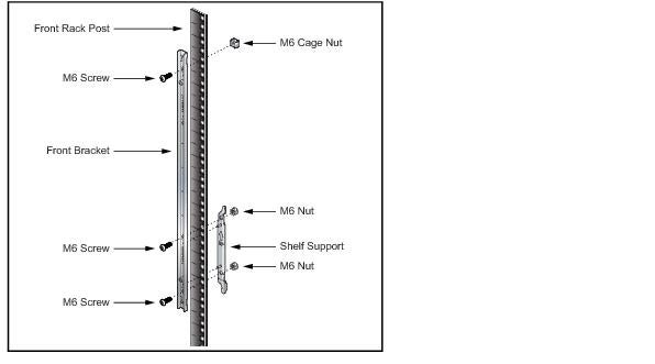
Figure 3-4: Left Front Post Assembly: Four Post Rack Mount
Step 2 Repeat step 1 on the right front rack post, assembling the parts at the same vertical level as those on the left rack post.
Step 3 Attach the shelf support and back bracket to the left rear post (Figure 3-5-left). The shelf support must be assembled at the same vertical level on the front and rear posts (Figure 3-5-right). An up arrow is printed on the shelf support to indicate its proper orientation.
Unthreaded rack holes: Attach the parts as displayed in Figure 3-5-left.
Threaded rack holes: Attach the shelf support to the post with screws that thread into the rack post. The back bracket is not required on threaded racks.
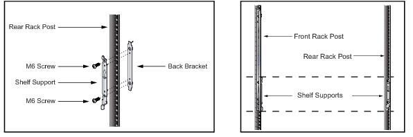
Figure 3-5: Left Rear Post Assembly and Shelf Support Orientation: Four Post Rack Mount
Step 4 Adjust the left shelf by sliding its components to fit between the front left and front rear rack posts, as shown in Figure 3-6.
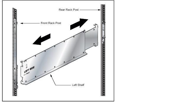
Figure 3-6: Adjusting the Left Shelf
Step 5 Lift the left shelf above the shelf supports installed on the left front and left rear rack posts (step 1 and step 3). Align the holes (Inset A) and hook (Inset B) with the stubs on the brackets. Lower the shelf such that the bracket stubs are inserted into the shelf holes and hook (Figure 3-7).
Press down firmly on the shelf to ensure it is seated securely on the rack posts.

Figure 3-7: Seating the Left Shelf
Step 6 Install the right shelf on the right front and right rear rack posts by repeating step 4 and step 5 to obtain the rack configuration shown in Figure 3-8.
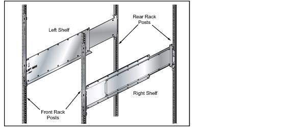
Figure 3-8: Both Switch Shelves Installed
Inserting the Switch into the Rack
Step 1 Move the chassis to the rack using a mechanical lift (Figure 3-9).
If modules are inserted in the chassis, use the lift carefully to avoid damaging any components.
Step 2 Lift the chassis into the rack.
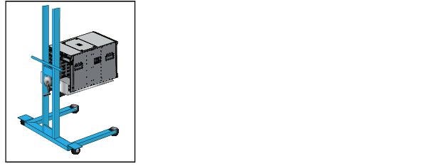
Figure 3-9: Lifting the Switch Chassis
Step 3 Secure the chassis by tightening the four thumbscrews on the front flanges into the rack posts (Figure 3-10).
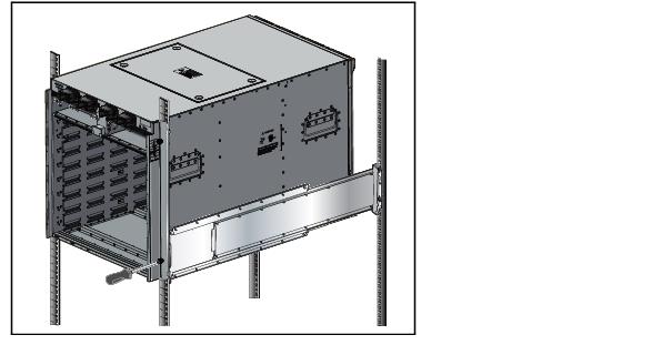
Figure 3-10: Inserting the Switch onto the Rack Shelf
After completing the Four-Post Installation, proceed to Chapter 4.