RoHS Declaration Statements

.
For Taiwan BSMI RoHS Table, go to https://www.arista.com/assets/data/pdf/AristaBSMIRoHS.pdf.

For Taiwan BSMI RoHS Table, go to https://www.arista.com/assets/data/pdf/AristaBSMIRoHS.pdf.
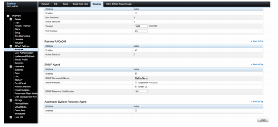
If you have a problem accessing the host externally, SSH into IPMI and access the host console.
The console redirect to serial over SSH, use an SSH client and complete the following steps.
Use the following steps to assemble the racking rails and attaching the components to the system.
This appendix displays the front panel of the CloudVision appliance.
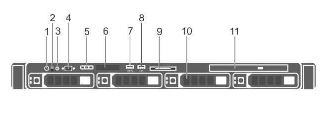
| Indicator, Button, or Connector | Description | |
|---|---|---|
| 1 | Power-on indicator, power button |
The power-on indicator lights when the system power is on. The power button controls the power supply output to the system. Note: On ACPI-compliant operating systems, turning off the system using the power button causes the system to perform a graceful shutdown before power to the system is turned off.
|
| 2 | NMI button |
Used to troubleshoot software and device driver errors when running certain operating systems. This button can be pressed using the end of a paper clip. Note: Use this button only if directed to do so by qualified support personnel.
|
| 3 | System identification button |
The identification buttons on the front and back panels can be used to locate a particular system within a rack. When one of these buttons is pressed, the system status indicator on the back flashes until one of the buttons is pressed again. Press to toggle the system ID on and off. If the system stops responding during POST, press and hold the system ID button for more than five seconds to enter BIOS progress mode. To reset the iDRAC (if not disabled in F2 iDRAC setup) press and hold the button for more than 15 seconds. |
| 4 | Video connector | Allows you to connect a display to the system. |
| 5 | Diagnostic indicators | The diagnostic indicator lights up to display error status. |
| 6 | LCD panel | Displays system ID, status information, and system error messages. |
| 7 |
USB management port/iDRAC managed USB port |
The USB management port can function as a regular USB port or provide access to the iDRAC features. |
| 8 | USB connector |
Allows you to connect USB devices to the system. The port is USB 2.0-compliant. |
| 9 | Information tag |
A slide-out label panel which contains system information such as Service Tag, NIC, MAC address, and so on for your reference. |
| 10 | Hard drives | Up to four 3.5 inch hot-swappable hard drives/SSDs. |
| 11 | Optical drive (optional) | One optional slim SATA DVD-ROM drive or DVD+/-RW drive. |
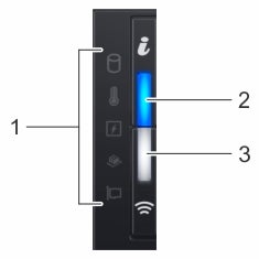
| Item | Indicator, button, or connector | Icon | Description |
|---|---|---|---|
| 1 | Status LED indicators | N/A | Indicate the status of the system. |
| 2 | System health and system ID indicator | Indicates the system health. | |
| 3 | IPMI Quick Sync 2 wireless indicator (optional)
Note: IPMI Quick Sync 2 wireless indicator is available only on certain configurations.
|
Indicates if the IPMI Quick Sync 2 wireless option is activated. The Quick Sync 2 feature allows management of the system using mobile devices. This feature aggregates hardware/firmware inventory and various system level diagnostic/error information that can be used in troubleshooting the system. You can access system inventory, Lifecycle Controller logs or system logs, system health status, and also configure IPMI, BIOS, and networking parameters. You can also launch the virtual Keyboard, Video, and Mouse (KVM) viewer and virtual Kernel-based Virtual Machine (KVM), on a supported mobile device. |
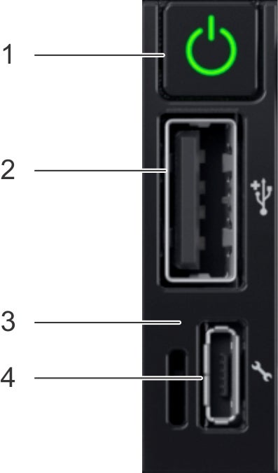
Item 1 is the power button, indicates if the system is turned on or off.
Item 2 is the USB port, enables you to connect USB devices to the system.
Item 3 is the iDRAC Direct LED, indicates that the IPMI Direct port is connected.
Item 4 is the iDRAC Direct port, enables you to access the IPMI direct features.
| Item | Indicator or button | Icon | Description |
|---|---|---|---|
| 1 | Power button | Power ON, power OFF. | |
| 2 | USB port | The USB ports are 4-pin, 2.0-compliant. This port enables you to connect USB devices to the system. | |
| 3 | IPMI Direct LED | N/A | The IPMI Direct LED indicator lights up to indicate that the IPMI Direct port is actively connected to a device. |
| 4 | IPMI Direct port (Micro-AB USB) | The IPMI Direct (Micro-AB USB) port enables you to access the IPMI Direct (Micro-AB) features. |
This appendix displays the back panel of the Arista CloudEOS and vEOS Router Appliance.
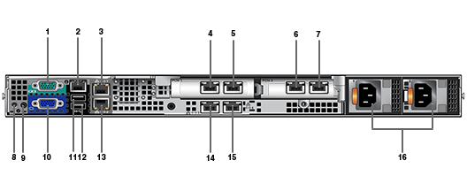
| Number | Indicator, Button, or Connector | Description |
|---|---|---|
| 1 | Serial connector | Allows you to connect a serial device to the system. |
| 2 | IPMI port (optional) | Dedicated management port on the IPMI ports card. |
| 3 | Ethernet connector 1 | Integrated 10/100/1000 Mbps NIC connector. |
| 4 | 10G Port 1 | Data Port 1 |
| 5 | 10G Port 2 | Data Port 2 |
| 6 | 10G Port 3 | Data Port 3 |
| 7 | 10G Port 4 | Data Port 4 |
| 8 | System identification button | The identification buttons on the front and back panels can be used to locate a particular system within a rack. When one of these buttons is pressed, the system status indicator on the back flashes until one of the buttons is pressed again.
Press to toggle the system ID on and off. If the system stops responding during POST, press and hold the system ID button for more than five seconds to enter BIOS progress mode. To reset the IPMI (if not disabled in F2 IPMI setup) press and hold the button for more than 15 seconds. |
| 9 | System identification connector | Connects the optional system status indicator assembly through the optional cable management arm. |
| 10 | Video connector | Allows you to connect a VGA display to the system. |
| 11 | USB connector | Allow you to connect USB devices to the system. The port is USB 2.0-compliant. |
| 12 | USB connector | Allow you to connect USB devices to the system. The port is USB 3.0-compliant. |
| 13 | Ethernet connector 2 | Integrated 10/100/1000 Mbps NIC connector. |
| 14 | Ethernet connector 3 | Port not used by CloudEOS and vEOS launcher scripts. |
| 15 | Ethernet connector 4 | Port not used by CloudEOS and vEOS launcher scripts. |
| 16 | Power supply (PSU1 and PSU2) | Up to two 550 W redundant AC power supplies. |
A number of tools are available to help manage and update images and insert ISO to the Virtual Machine (VM).
Arista provides an ISO with all updated packages and a tool to mount the images ISO and upgrade the system.
To upgrade the Host image, complete the following steps.
To upgrade a single node CVA, perform all the steps listed in Steps to Upgrade the CVA. After the CVA host comes up, and after rebooting the system from the last step of upgrade, allow 20 minutes for the CVP application to be accessible again.
Perform a rolling upgrade to update the CVA systems in multi-node configuration. Perform all the steps listed in section Steps to Upgrade the CVA from the start to finish on only one of the CVAs at a time. After the upgrade, wait for all the VMs, (CVP and CVX) to be fully up and running (CVP takes 20 minutes to be up from reboot). Verify that the CVP is accessible. After the verification, proceed to upgrade the second CVA host in a similar fashion and then the third CVA.
The system's LCD panel provides system information and status and error messages to indicate if the system is operating correctly or if the system needs attention.
The LCD back-light lights blue during normal operating conditions.
When the system needs attention, the LCD lights amber and displays an error code followed by descriptive text.
The LCD back-light turns OFF when the system is in standby mode and can be turned on by pressing either the Select, Left, or Right button on the LCD panel.
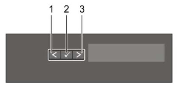
| Item | Button | Description |
|---|---|---|
| 1 | Left | Moves the cursor back in one-step increments. |
| 2 | Select | Selects the menu item highlighted by the cursor. |
| 3 | Right | Moves the cursor forward in one-step increments.
During message scrolling:
|
| Icon | Description | Condition | Corrective action |
|---|---|---|---|
 |
Drive indicator | The indicator turns solid amber if there is a drive error. |
|
 |
Temperature indicator | The indicator turns solid amber if the system experiences a thermal error (for example, the ambient temperature is out of range, or there is a fan failure). | Ensure that none of the following conditions exist:
|
 |
Electrical indicator | The indicator turns solid amber if the system experiences an electrical error (for example, voltage out of range, or a failed power supply unit (PSU) or voltage regulator). | Check the System Event Log or system messages for the specific issue. If it is due to a problem with the PSU, check the LED on the PSU. Reseat the PSU. |
 |
Memory indicator | The indicator turns solid amber if a memory error occurs. | Check the System Event Log or system messages for the location of the failed memory. Reseat the memory module. |
 |
PCIe indicator | The indicator turns solid amber if a PCIe card experiences an error. | Restart the system. Update any required drivers for the PCIe card. Reinstall the card. |
The IPMI Direct LED indicator lights up to indicate that the port is connected and is being used as a part of the IPMI system.
You can configure IPMI Direct by using a USB to micro USB (type AB) cable, which you can connect to your laptop or tablet. The following table describes IPMI Direct activity when the IPMI Direct port is active:
| IPMI Direct LED Indicator Code | Condition |
|---|---|
| Solid green for two seconds | Indicates that the laptop or tablet is connected. |
| Flashing green (on for two seconds and off for two seconds) | Indicates that the laptop or tablet connected is recognized. |
| Turns off | Indicates that the laptop or tablet is unplugged. |
The IPMI Quick Sync 2 module (optional) is located on the left control panel of your system.

| IPMI Quick Sync 2 indicator code | Condition | Corrective action |
|---|---|---|
| Off (default state) | Indicates that the IPMI Quick Sync 2 feature is turned off. Press the IPMI Quick Sync 2 button to turn on the IPMI Quick Sync 2 feature. | If the LED fails to turn on, reseat the left control panel flex cable and check. |
| Solid white | Indicates that IPMI Quick Sync 2 is ready to communicate. Press the IPMI Quick Sync 2 button to turn off. | If the LED fails to turn off, restart the system. |
| Blinks white rapidly | Indicates data transfer activity. | |
| Blinks white slowly | Indicates that firmware update is in progress. | |
| Blinks white five times rapidly and then turns off | Indicates that the IPMI Quick Sync 2 feature is disabled. | Check if IPMI Quick Sync 2 feature is configured to be disabled by IPMI. |
| Solid amber | Indicates that the system is in fail-safe mode. | Restart the system. |
| Blinking amber | Indicates that the IPMI Quick Sync 2 hardware is not responding properly. | Restart the system. |
Each NIC on the back of the system has indicators that provide information about the activity and link status. The activity LED indicator indicates if data is flowing through the NIC, and the link LED indicator indicates the speed of the connected network.
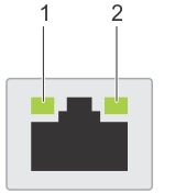
| Status | Condition |
|---|---|
| Link and activity indicators are off | The NIC is not connected to the network. |
| Link indicator is green, and activity indicator is blinking green | The NIC is connected to a valid network at its maximum port speed and data is being sent or received. |
| Link indicator is amber and activity indicator is blinking green | The NIC is connected to a valid network at less than its maximum port speed and data is being sent or received. |
| Link indicator is green, and activity indicator is off | The NIC is connected to a valid network at its maximum port speed and data is not being sent or received. |
| Link indicator is amber and activity indicator is off | The NIC is connected to a valid network at less than its maximum port speed and data is not being sent or received. |
| Link indicator is blinking green and activity is off | NIC identify is enabled through the NIC configuration utility. |
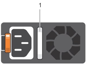
| Power indicator codes | Condition |
|---|---|
| Green | A valid power source is connected to the PSU, and the PSU is operational. |
| Blinking amber | Indicates a problem with the PSU. |
| Not illuminated | Power is not connected to the PSU. |
| Blinking green | When the firmware of the PSU is being updated, the PSU handle blinks green.
CAUTION: Do not disconnect the power cord or unplug the PSU when updating the firmware. If the firmware update is interrupted; the PSUs do not function.
|
| Blinking green and turns off | When hot-plugging a PSU, the PSU handle blinks green five times at a rate of 4 Hz and turns off. This indicates a PSU mismatch concerning efficiency, feature set, health status, or supported voltage.
CAUTION: If two PSUs are installed, both the PSUs must have the same type of label; for example, Extended Power Performance (EPP) label. Mixing PSUs from previous generations of PowerEdge servers is not supported, even if the PSUs have the same power rating. This results in a PSU mismatch condition or failure to turn the system on.
CAUTION: When correcting a PSU mismatch, replace only the PSU with the blinking indicator. Swapping the PSU to make a matched pair can result in an error condition and unexpected system shutdown. To change from a high output configuration to a low output configuration or vice versa, you must turn off the system.
CAUTION: AC PSUs support both 240 V and 120 V input voltages except for Titanium PSUs, which support only 240 V. When two identical PSUs receive different input voltages, they can output different wattage, and trigger a mismatch.
CAUTION: If two PSUs are used, they must be of the same type and have the same maximum output power.
|
In order to use the CloudEOS and vEOS router, use the following link to access the vEOS Router Configuration Guide to create vEOS routers. https://www.arista.com/en/support/product-documentation.
To install the base CVA OS image, complete the following steps.
Once the base CVA OS image is installed, complete the following steps to build the CloudEOS and vEOS Router Appliance.
Pre-installation Checklist
The CloudEOS and vEOS Router Appliance, which is based on the Arista EOS, runs as a virtual machine instance on Azure. Use the CloudEOS and vEOS Router Appliance to create the various types of virtual machine router instances you need for your Azure deployment. For example, gateway routers and transit routers.
The process you use to update CloudEOS and vEOS Router Appliance images is the standard update process used for EOS images.
For details on the steps to use, refer to the Arista EOS User Manual, see https://www.arista.com/en/support/product-documentation.
Describes the CloudEOS and vEOS Router Appliance Azure minimum support requirements.
The CloudEOS and vEOS Router Appliance Azure instance supports the following instance types:
There are two methods which can be used to launch a CloudEOS and vEOS Router Appliance instance.
Below is a summary of each method.
Do not deploy the same template twice into a single resource group, because this creates name conflicts. To deploy multiple instances into the same resource group, modify the template, so all resources are renamed, and all IP addresses are unique.
To create an instance using the Portal Marketplace, complete the following steps.
To create an instance under Azure CLI 2.0, complete the following steps.
#!/usr/bin/bash
cat $1 | python -c 'import json, sys; print( json.dumps( sys.stdin.read() ) )'$ az group create --name ExampleGroup --location "Central US"$ az group deployment create \
--name ExampleDeployment \
--resource-group ExampleGroup \
--template-file <prefix>-template.json \
--parameters @<prefix>-parameters.jsonTo log into an instance, complete the following steps.
Describes launch employing custom-data information.
During the initial launching of the CloudEOS and vEOS Router Instance, Azure provides a feature to upload custom-data. The administrator can upload the CloudEOS and vEOS Router configuration using custom-data at the time of the launching of the CloudEOS and vEOS Router Instance.
Custom-data can be used to pass in configuration for multiple entities. This configuration must be separated by start and end markers.
| Entity | Markers | File Path |
|---|---|---|
| CloudEOS and vEOS CLI configuration file |
|
N/A |
| Cloud HA configuration file |
|
/mnt/flash/cloud_ha_config.json |
Note, the following regarding the custom-data.
Illustrates a sample Instance with custom-data.
%EOS-STARTUP-CONFIG-START%
! EOS startup config
username admin nopassword
username admin sshkey file flash:key.pub
%EOS-STARTUP-CONFIG-END%
Adding custom-data to an instance.
Currently, custom-data can only be used on instances deployed using the Azure CLI 2.0.
In order to add custom-data to an instance, the custom-data must be provided as a single-line value with '\n' delimiting newlines.
Use the single_line_json.sh script to convert your custom-data into this format.
#!/usr/bin/bash
cat $1 | python -c 'import json, sys; print( json.dumps( sys.stdin.read() ) )'
Usage of the script is as follows:
./single_line_json.sh user_data.txtCopy and paste the generated output into the customData value field of the JSON parameters file.
To troubleshoot the instance, complete the following steps.
Additional resources.