Taiwan RoHS Information
This section provides the Taiwan RoHS information for switches covered by this guide.
For the Taiwan BSMI RoHS Table, go to https://www.arista.com/assets/data/pdf/AristaBSMIRoHS.pdf.
This section provides the Taiwan RoHS information for switches covered by this guide.
For the Taiwan BSMI RoHS Table, go to https://www.arista.com/assets/data/pdf/AristaBSMIRoHS.pdf.
This section lists the Regulatory Model Numbers (RMNs), where applicable, for the product models for the switches described in this document.
| Regulatory Model Number (RMN) | Product Number(s) |
|---|---|
| CCS-755 | CCS-755 |
| CCS-758 | CCS-758 |
This section describes the process for replacing switch components. You must ensure that at least one of the secondary grounding pads located on the front panel of the chassis is connected to the data center ground. While working on the switches, use grounded, anti-static wrist straps connected to one of the attach points on the switch for grounding yourself and preventing ESD damage to the switch.
The fan modules are hot-swappable and N + 1 redundant. They are accessible from the rear of the switch (Rear Panel). You must take into account that the module you are inserting is compatible with the switch and the module that you are replacing. Perform the following steps to remove and replace a fan module.
The supervisor modules are hot-swappable. They are accessible from the front of the switch. You must take into account that the module you are inserting is compatible with the switch and the module that you are replacing. Use the following procedure to remove and replace a supervisor module. For the supervisor module locations for your device, refer to Front Panel.
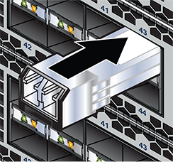
The linecards are hot-swappable. They are accessible from the front of the switch. You must take into account that the linecard you are inserting is compatible with the switch and the linecard that you are replacing. Use the following procedure to remove and replace a linecard. If you are adding a new linecard, remove the blank from the linecard slot and install the new linecard. For the linecard locations on your switch, refer to Front Panel. Figure 1 - CCS-75x Linecard Install shows linecards with the seating or ejector mechanisms along with some fully seated linecards.
.png)
| 1 | Linecard | 3 | Ejector lever (linecard seated correctly) |
| 2 | Ejector mechanism (lever and handle) | 4 | Ejector lever (linecard not seated) |
The switchcards are hot-swappable and 1 + 1 redundant. They are accessible from the rear of the switch (Rear Panel). You must take into account that the switchcard you are inserting is compatible with the switch and the switchcard that you are replacing. Use the following procedure to remove and replace a switchcard. For the switchcard locations on your switch, refer to Rear Panel.
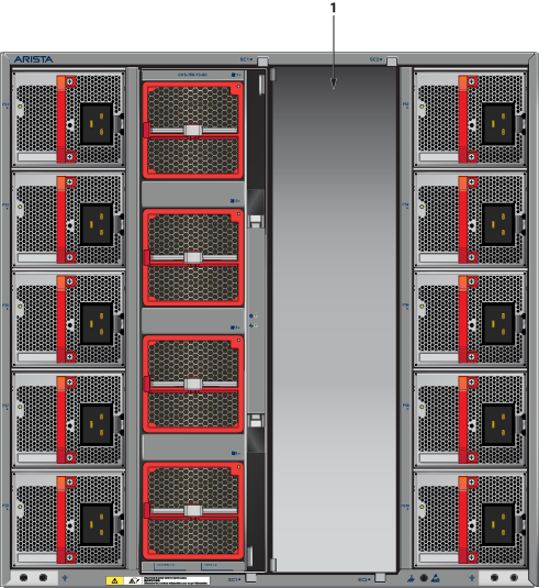
| 1 | SC2 cover |
Figure 3 - 758 Switchcard Installation shows switchcard installation. The switchcard on the right is fully seated with the latch closed.
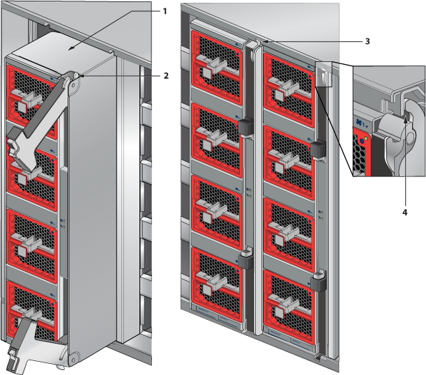
| 1 | Switchcard | 3 | Ejector (switchcard not seated) |
| 2 | Ejector mechanism (handle and latch) | 4 | Ejector latch (closed) |
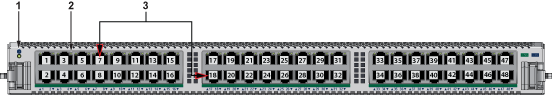
This section displays the linecards supported by modular switches covered by this guide.
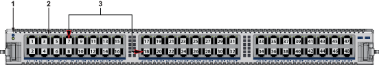
| 1 | Linecard status LED | 2 | Port status LED | 3 | Port numbers |
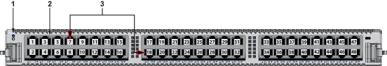
| 1 | Linecard status LED | 2 | Port status LED | 3 | Port numbers |
| 1 | Linecard status LED | 2 | Port status LED | 3 | Port numbers |
| 1 | Linecard status LED | 2 | Port status LED | 3 | Port numbers |
This section displays the rear panel of all switches covered by this guide.
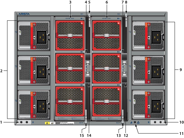
| 1 | Chassis ground | 6 | Fans and switchcard module 2 | 11 | ESD attachment point |
| 2 | PSUs (1, 3, 5 - From top) | 7 | Switchcard ejector - SC2 | 12 | Switchcard ejector - SC2 |
| 3 | Fans and switchcard module 1 | 8 | Ejector latch - SC2 | 13 | Ejector latch - SC2 |
| 4 | Switchcard ejector - SC1 | 9 | PSUs (2, 4, 6 - From top) | 14 | Switchcard ejector - SC1 |
| 5 | Ejector latch - SC1 | 10 | Chassis ground | 15 | Ejector latch - SC1 |
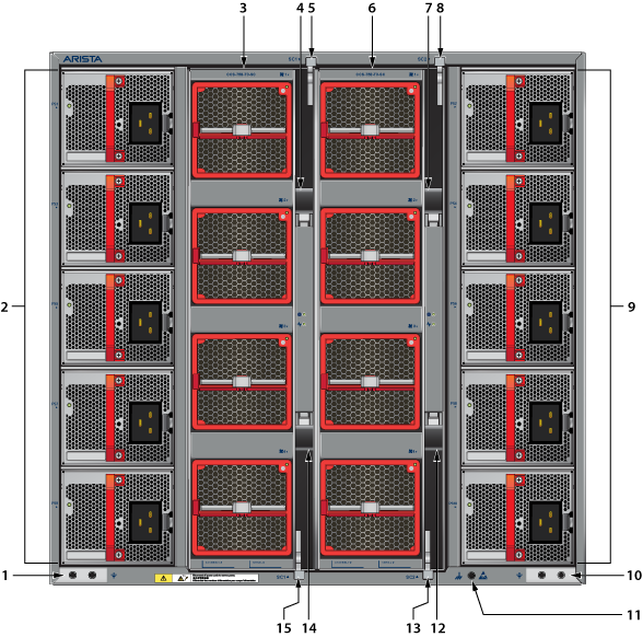
| 1 | Chassis ground | 6 | Fans and switchcard module 2 | 11 | ESD attachment point |
| 2 | PSUs (1, 3, 5, 7, 9 - From top) | 7 | Switchcard ejector - SC2 | 12 | Switchcard ejector - SC2 |
| 3 | Fans and switchcard module 1 | 8 | Ejector latch - SC2 | 13 | Ejector latch - SC2 |
| 4 | Switchcard ejector - SC1 | 9 | PSUs (2, 4, 6, 8, 10 - From top) | 14 | Switchcard ejector - SC1 |
| 5 | Ejector latch - SC1 | 10 | Chassis ground | 15 | Ejector latch - SC1 |
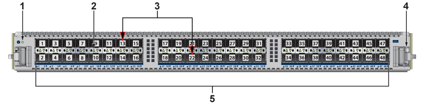
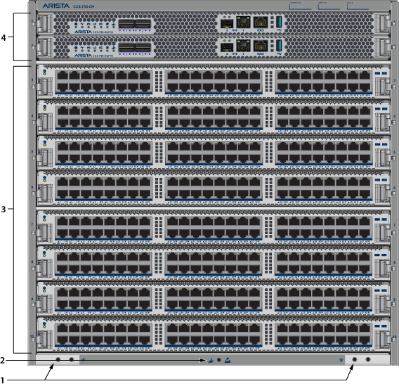
This section displays the front panel of all switches covered by this guide.
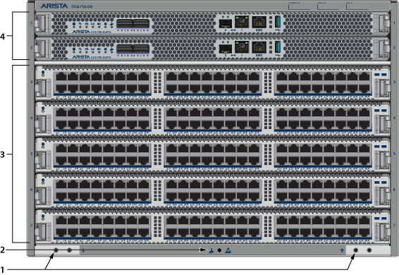
| 1 | Grounding locations | 3 | Linecards | ||
| 2 | ESD attach point | 4 | Supervisor modules |

| 1 | Grounding locations | 3 | Linecards | ||
| 2 | ESD attach point | 4 | Supervisor modules |
Each switch has an accessory kit that contains parts required to install the switch.Table 1 - Accessory Kits for the Modular Switches provides further details on the accessory kit for each switch. The following sections in the chapter list the installation parts provided by the accessory kit in more details.
| 755 | 758 | |
|---|---|---|
| Common cables and accessories | Included | Included |
| Two-post rack mount kit (KIT-CCS-750 | Included | Included |
| Four-post rack mount kit (KIT-CCS-750-4P) | Optional | Optional |
| Four-post rack mount kit (KIT-CCS-750-4PL) | Optional | Optional |
| Optional | ||
| Power Cords | ||
All provided power cables are for use only with Arista products.
Câbles d’alimentation doivent être utilisés uniquement avec des produits de Arista.

| Quantity | Description |
|---|---|
| 1 | RJ45 To DB9 Adapter with a 6-foot rolled cable. |
| 1 | Seven-foot RJ45 Patch panel cable. |
One 2-page document.
The following sections list the parts provided in the accessory kit for two-post rack mount installations.
| Quantity | Description |
|---|---|
| 1 | Cradle assembly. |
| 4 | Mounting brackets/ears (flange). |
| 16 | Rack mounting screws and rack nuts |
| 16 | Flat-head screws |
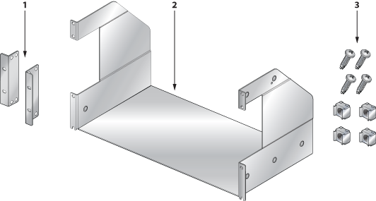
| 1 | Mounting brackets/ears | 2 | Cradle assembly | 3 | Rack mounting screws and rack nuts |
The following sections list the parts provided in the accessory kit for four-post rack mount installations.
| Quantity | Description |
|---|---|
| 1 | Cradle assembly. |
| 4 | Mounting brackets/ears (flange). |
| 20 | Rack mounting screws and rack nuts |
| 16 | Flat-head screws |
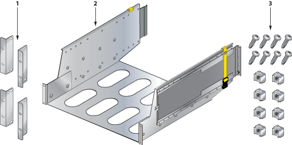
| 1 | Mounting brackets/ears | 2 | Cradle assembly | 3 | Rack mounting screws and rack nuts |
The following sections list the parts provided in the accessory kit for four-post rack mount installations.
| Quantity | Description |
|---|---|
| 1 | Cradle assembly. |
| 4 | Mounting brackets/ears (flange). |
| 20 | Rack mounting screws and rack nuts |
| 16 | Flat-head screws |
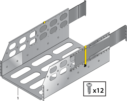
| 1 | Mounting brackets/ears | 2 | Cradle assembly | 3 | Rack mounting screws and rack nuts |
The system status indicator LEDs are shown in Figure 1 - Supervisor CCS-750-SUP100 and Figure 2 - Supervisor CCS-750-SUP25 .
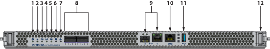
| 1 | Supervisor status LED | 5 | Switch card status LED | 9 | Ethernet management ports |
| 2 | Supervisor active status LED | 6 | Fan status LED | 10 | RJ-45 Serial console port |
| 3 | PSU status LED | 7 | Uplink status LED | 11 | USB Port |
| 4 | Linecard status LED | 8 | QSFP100 uplink ports | 12 | Release/locking mechanism (Right)1 |
1 There is a similar mechanism on the left.
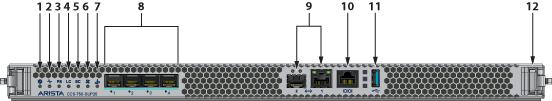
| 1 | Supervisor status LED | 5 | Switch card status LED | 9 | Ethernet management ports |
| 2 | Supervisor active status LED | 6 | Fan status LED | 10 | RJ-45 Serial console port |
| 3 | PSU status LED | 7 | Uplink status LED | 11 | USB Port |
| 4 | Linecard status LED | 8 | SFP25 uplink ports | 12 | Release/locking mechanism1 |
1 There is a similar mechanism on the left.
Table 1 - Supervisor Status LED States interprets the states of the supervisor status LED. s for both the active and the redundant supervisor module.
| State | Status |
|---|---|
| Off | Supervisor has no power or is powering up. |
| Blinking Green | Supervisor is booting. System can take up to 30 minutes to come up. All other LEDs will also be off. |
| Green | Supervisor is operating normally (master supervisor). System is good. |
| Yellow/Amber/Orange | System is overheating or has been disabled by software. |
| Blinking Blue | Locater function enabled by CLI (Beacon). |
Table 2 - Supervisor Active Status LED States interprets the states of the supervisor active status LED.
| State | Status |
|---|---|
| Off | Supervisor is the standby supervisor. All other LEDs except Supervisor Status remain off. |
| Green | Supervisor is the Active supervisor. |
Table 3 - PSU Status LED States interprets the states of the PSU status LED.
| State | Status |
|---|---|
| Off | PSU not detected, installed or powered. |
| Green | All installed PSUs are operating normally. |
| Red | One or more PSU has a fault. |
Table 4 - Linecard Status LED States interprets the states of the Linecard status LED.
| State | Status |
|---|---|
| Off | Linecard not detected, installed or powered. |
| Green | All installed linecards are operating normally. |
| Yellow/Amber/Orange | One or more linecard is booting up or being updated. |
| Red | One or more linecards have failed. |
Table 5 - Switchcard Status LED States interprets the states of the switchcard status LED.
| State | Status |
|---|---|
| Off | Switchcard not detected, installed or powered. |
| Green | All installed switchcards are operating normally. |
| Yellow/Amber/Orange | One or more switchcard is booting up or being updated. |
| Red | One or more switchcards have failed. |
Table 6 - Fan Status LED States interprets the states of the Fan status LED.
| State | Status |
|---|---|
| Off | No fan detected. |
| Green | All installed fans are operating normally. |
| Yellow/Amber/Orange | One or more fans has failed or is missing. |
| Red | Fans are insufficient or incompatible. |
Table 7 - Management Ethernet Port Status LED States interprets the states of the management Ethernet port status LED.
| LED | State | Status |
|---|---|---|
| Left | Off | Port is not linked up. |
| Left | Green | Port is linked up. |
| Right | Off | Port has no activity. |
| Right | Green | Port has activity. |
Table 8 - Uplink Status LED States interprets the states of the uplink status LED.
| State | Status |
|---|---|
| Off | Supervisor is not powered up or inserted. |
| Green | Uplink card is operating normally. |
| Yellow/Amber/Orange | Uplink card is booting up or being updated. |
| Red | Uplink card power has failed. |
Each linecard module provides one status LED plus LEDs for each port on the card.Figure 3 - Linecard Module Status LEDs shows a representative line card. The figures in Linecards indicate the location of the LEDs on each linecard.
.png)
| 1 | Linecard module status LED | 2 | Port status LED |
Table 9 - Linecard Module Status LED States interprets the states of the linecard module status LED located on the individual linecard.
| State | Status |
|---|---|
| Off | Linecard not inserted or powered. |
| Green | Linecard operating normally. |
| Yellow/Amber/Orange | Linecard is booting up or being updated. |
| Blinking Red | Locater function is enabled (Beacon). |
| Red | Linecard has failed. |
Table 10 - Port Status LED States interprets the states of the port status LED located by each port on the linecard.
| State | Status |
|---|---|
| Off | Port link is down. |
| Green | Port link is up. |
| Yellow/Amber/Orange | Port is being administered by software. |
| Blinking Yellow/Amber/Orange | Locater function is enabled (Beacon). |
Rear Panel displays the position of the Switchcard Module Status LEDs on the rear of each switch. Figure 4 - 755 Switchcard Module and Fan Module Status LEDs displays fan module status and switch card module status LEDs on the 755 switch.
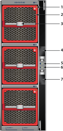
| 1 | Fan module 1 status LED | 4 | Switchcard release | 7 | Switchcard release |
| 2 | Fan module 1 | 5 | Switchcard module status LED | ||
| 3 | Fan module 1 release | 6 | Switchcard module active status LED |
758 Switchcard Module and Fan Module Status LEDs displays fan module status and switchcard module status LEDs on the 758 switch.
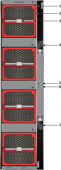
| 1 | Fan module 1 status LED | 4 | Switchcard release | 7 | Switchcard release |
| 2 | Fan module 1 | 5 | Switchcard module status LED | ||
| 3 | Fan module 1 release | 6 | Switchcard module active status LED |
There are two LEDs for the Switchcard status. Only one of the switch cards is active. The second provides redundancy. The switchcard module LEDs are on the rear panel of the switches.
Switchcard Module Status LED States interprets the states of the switchcard module status LED.
| State | Status |
|---|---|
| Off | Switchcard does not have power. |
| Green | All installed switchcards are working normally. |
| Yellow/Amber/Orange | Switchcard is booting up or being updated. |
| Red | One or more switchcards have failed. |
Switchcard Module Active Status LED States interprets the states of the switchcard module active status LED.
| State | Status |
|---|---|
| Off | Switchcard is in standby mode. |
| Green | Switchcard is in active mode. |
The fan module status LED are on the fan modules.Figure 6 - Fan Module Status LED displays the LED on the fan module.
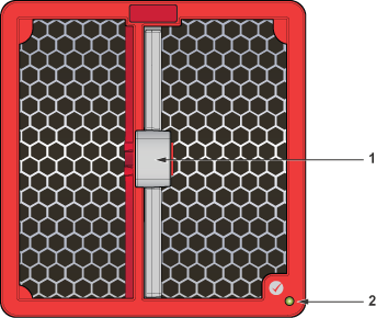
| 1 | Release | 2 | Fan module status LED |
Table 13 - Fan Module Status LED States interprets the states of the switch card module active status LED.
| State | Status |
|---|---|
| Off | Fan does not have power. |
| Green | Fan module is working normally. |
| Flashing red | Locater function is enabled (Beacon). |
| Red | Fan module has failed. |
The power supply status LED ison the power supply modules.Figure 7 - AC Power Supply (PWR-3351-AC-RED) displays the LED on the PWR-3351-AC-RED AC power supply.
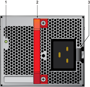
| 1 | Status LED | Handle | 3 | Release |
Table 14 - AC Power Supply Status LED States interprets the AC power supply module LED status indicators with multiple PSU present in the system.
| State | Status |
|---|---|
| Off | No AC Input or 140V < AC < 175V - single PSU. |
| Blinking Amber1 | No AC Input or 140V < AC < 175V – multiple PSUs. |
| Blinking Green1 | Standby Mode. |
| Green | Normal Operation. |
| Amber | PSU module has failed. |
| Blinking Amber and Green2 | Boot Loader. |
1 1 second ON, 1 second OFF.
2 1 second ON, alternating.
When bypassing ZTP, initial switch access requires logging in as admin, with no password, through the console port. Then you can configure an admin password and other password protected usernames.
This manual configuration procedure cancels ZTP mode, logs into the switch, assigns a password to admin, assigns an IP address to the management port, and defines a default route to a network gateway.
As the switch boots without a startup-config file, it displays this message through the console:
The device is in Zero Touch Provisioning mode and is attempting to
download the startup-config from a remote system. The device will not
be fully functional until either a valid startup-config is downloaded
from a remote system or Zero Touch Provisioning is cancelled. To cancel
Zero Touch Provisioning, login as admin and type 'zerotouch cancel'
at the CLI.

localhost login:
localhost login: admin
localhost> zerotouch cancel
Arista EOS
localhost login: admin
Last login: Fri Mar 15 13:17:13 on console
localhost> enable
localhost# config
localhost(config)# username admin secret pxq123
localhost(config)# ip route 0.0.0.0/0 192.0.2.1
localhost(config)# interface management 1/1
localhost(config-if-Ma1/1)# ip address 192.0.2.8/24
localhost# copy running-config startup-config
ssh admin@192.0.2.8
Refer to the Arista Networks User Manual for complete switch configuration information.
Before you begin, refer to the Arista Networks document Compliance and Safety Guide available at:https://www.arista.com/en/support/product-documentation.
Power down the switch: Remove all power cords from the power inlets.
Mettez le commutateur: Retirez tous les cordons d'alimentation des prises d'alimentation.
Installation of this equipment must comply with local and national electrical codes. If necessary, consult with the appropriate regulatory agencies and inspection authorities to ensure compliance.
Installation de cet équipement doit être conformes aux codes électriques locaux et nationaux. Si nécessaire, consulter les organismes de réglementation appropriés et des autorités de contrôle pour assurer la conformité.
Many configurations will require additional power supplies.
Nombreuses configurations exigera des alimentations supplémentaires.
Read all installation instructions before connecting the system to the power source.
Lire toutes les instructions d'installation avant de brancher le système à la source d'alimentation.
Table 2 - Power Supply Configurations shows the minimum number of operating power supplies that must be connected to active circuits for each switch to operate.
Each power supply includes a fan that maintains proper power supply temperature. The appendices display the location of components for all switches described in this guide.
Figure 1 - Chassis Ground Locations (CCS-755) and Figure 2 - Chassis Ground Locations (CCS-758) display the location of the chassis grounding locations on the front panel of the switches. Chassis ground locations are also located on the rear panel of the switch chassis (Rear Panel). After mounting the switch into the rack, connect at least one of the chassis grounds to the data center ground using two-hole ground lugs with 16 mm (5/8 in.) spacing, and two M4 x 0.7 screws. After the switch is grounded, ESD wrist straps can be grounded by connecting them to one of the attach points.
Grounding wires and grounding lugs are not supplied. Wire size should meet local and national installation requirements. Commercially available 2 or 4 AWG wire is recommended for installations in the U.S.
À la terre et de mise à la terre fils cosses ne sont pas fournis. Calibre des fils doit satisfaire des exigences de l'installation locale et nationale. Disponible dans le commerce 2 ou 4 AWG fil est recommandé pour les installations aux États-Unis.
This equipment must be grounded. Never defeat the ground conductor. This unit requires over-current protection.
Cet équipement doit être mis à la terre. Ne jamais modifier le conducteur de terre. Cet appareil nécessite de protection contre les surintensités.
Secondary Grounding wires, lugs, and screws (M4 x 0.7) are not supplied.
Secondaire à la terre, câbles, cosses et vis (M4 x 0.7) ne sont pas fournis.

| 1 | Grounding locations | 3 | Line cards |
| 2 | ESD attach point | 4 | Supervisor modules |
| 1 | Grounding locations | 3 | Line cards |
| 2 | ESD attach point | 4 | Supervisor modules |
To power down the switch,remove all power cords from the power inlets.
The switches use PWR-3351-AC-RED (Figure 3 - AC Power Supply (PWR-3351-AC-RED)) AC power supplies. Power cables are included with the accessory kit (Table 1 - Accessory Kits for the Modular Switches). To power the switch, connect the cables to the C20 connectors on the PSU inputs, and insert the other side of the cables into the main power providing circuit(s).
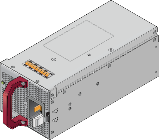
The Rear Panel displays the rear panel location of the power supplies.
Table 1 - Power Supply Specifications (each PSU) shows the power supply specifications for each of the PSUs supported.
| Power Supply | Maximum Output Power Rating (DC) | Input Voltage and Frequency | Maximum Input Current | Input Branch Circuit Protection |
|---|---|---|---|---|
| PWR-3351-AC-RED | 1400 W 3000 W 3300 W | 100 to 127 VAC 200 to 220 VAC 220 to 240 VAC 50/60 Hz | 16 A | 20 A |
Each power supply requires input branch circuit protection in compliance with AHJ requirements.
Chaque alimentation nécessite une protection du circuit de la branche d’entrée conformément aux exigences de l’AHJ.
Table 2 - Power Supply Configurations shows the power supply configurations for the modular switches.
| Modular Switch | Recommended Number of PSUs (for redundancy) | Minimum Number of PSUs Required | Maximum Number of PSUs Supported |
|---|---|---|---|
| CCS-755 | 3 | 1 | 6 |
| CCS-758 | 5 | 1 | 10 |
Installation of this equipment must comply with local and national electrical codes. If necessary, consult with the appropriate regulatory agencies and inspection authorities to ensure compliance.
Installation de cet équipement doit être conformes aux codes électriques locaux et nationaux. Si nécessaire, consulter les organismes de réglementation appropriés et des autorités de contrôle pour assurer la conformité.
Read all installation instructions before connecting the system to the power source.
Lire toutes les instructions d'installation avant de brancher le système à la source d'alimentation.
Most installations will have redundant, dual, independent power feeds. Each independent power feed will be referenced as A and B.
The recommended installation is to wire each supply to independent power feed (A or B).
Each power supply includes a fan that maintains proper power supply temperature. The following appendices display the location of the following component on all switches described in this guide.
The Front Panel displays the front panel location of the supervisor modules and line cards.
The Rear Panel displays the rear panel location of switch card modules (not visible), fans, and PSUs.
This unit requires over-current protection.
Cet appareil nécessite de protection contre les surintensités.
Unused slots must be occupied or covered with a blank to ensure proper airflow through the chassis.
Les emplacements inutilisés doivent être occupés ou recouvert d'un blanc pour assurer la bonne circulation d'air dans le châssis.
Supervisor modules contain console, management, and USB ports. Figure 4 - Supervisor CCS-750-SUP100display port and status LED locations on the supervisors. Refer to the chassis specification in Connecting Supervisor Cables for additional information about the serial port.

| 1 | Supervisor status LED | 5 | Switch card status LED | 9 | SFP and RJ-45 Ethernet management ports |
| 2 | Supervisor active status LED | 6 | Fan status LED | 10 | RJ-45 Serial management port |
| 3 | PSU status LED | 7 | Uplink status LED | 11 | USB Port |
| 4 | Linecard status LED | 8 | Supervisor/Uplink ports (2x QSFP100) | 12 | Release |

| 1 | Supervisor status LED | 5 | Switch card status LED | 9 | SFP and RJ-45 Ethernet management ports |
| 2 | Supervisor active status LED | 6 | Fan status LED | 10 | RJ-45 Serial management port |
| 3 | PSU status LED | 7 | Uplink status LED | 11 | USB Port |
| 4 | Linecard status LED | 8 | Supervisor/Uplink ports (4x SFP25) | 12 | Release |
The supervisor cards must be installed in one of the two slots designated for them. They are shown in Front Panel for the switches.
| RJ-45 | DB-9 | RJ-45 | DB-9 | |||||
|---|---|---|---|---|---|---|---|---|
| RTS | 1 | 8 | CTS | GND | 5 | 5 | GND | |
| DTR | 2 | 6 | DSR | RXD | 6 | 3 | TXD | |
| TXD | 3 | 2 | RXD | DSR | 7 | 4 | DTR | |
| GND | 4 | 5 | GND | CTS | 8 | 7 | RTS | |
Install required SFP, SFP+, QSFP+, QSFP100, OSFP, and QSFP-DD optic modules in linecard module ports Figure 6 - SFP or SFP+ Ports .
Connect cables as required to linecard module ports. Supervisor and linecard module ejectors on the front of the chassis assist with cable management.
Excessive bending can damage interface cables, especially optical cables.
Flexion excessive peut endommager les câbles d'interface, en particulier les câbles optiques.