Appendix B: Product Compliance
Singapore IMDA Registration Mark
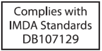
Singapore IMDA Registration Mark

The AP-server communication begins with a mutual authentication step in which the AP and server authenticate each other using a shared secret. The AP-server communication takes place only if this authentication succeeds.
After the authentication succeeds, a session key is generated. All communication between the AP and server from this point on is encrypted using the session key.
The AP and server are shipped with the same default value of the shared secret. The CLI commands are provided on both server and AP for changing the shared secret.
| Diagnosis | Solution |
|---|---|
| The device did not receive a valid IP address via the DHCP. | Ensure that the DHCP server is On and available on the VLAN/subnet to which the device is connected. If the device still fails to get a valid IP address, you can reboot it to see if the problem is resolved. |
| The Ethernet cable is loose. The device is probably disconnected from the network. | Ensure that the Ethernet cable is connected. |
| Unable to connect to the server. | Ensure that the server is running and is reachable from the network to which the device is attached. If there is a firewall or a router with ACLs enabled between the device and the server, ensure that the traffic is allowed on UDP port 3851. Use the server IP-based discovery and ensure that you have correctly entered the DNS name, wifi-security-server , on the DNS server. Also, ensure that the DNS server IP addresses are either correctly configured on the, or are provided by the DHCP server. It is also possible that the AP is unable to connect to the server because it has failed to authenticate with the server. In this case, an 'Authentication failed for ' event is raised on the server. Refer to the event for recommended action. |
| The AP has encountered a problem. | If you are using Arista Cloud Services, then open the TCP port 443 (SSL). If you have an on-premises installation, then open the ports UDP 3851 and port 80. If you are using a Proxy, Web Accelerator or URL Content Filter in between the AP and the Internet, ensure the settings allow communication between the AP and Arista Cloud Services. If your configuration requires you to specify an exact IP address or IP range for Arista Cloud Services, please contact Technical Support. |
This chapter contains the stepwise procedure to install the W-118 device.
Zero-configuration is supported under the following conditions:
The device has no SSID configured.
A DNS entry wifi-security-server is set up on all the DNS servers. This entry should point to the IP address of the server. By default, the device looks for the DNS entry wifi-security-server.
The device is placed on a subnet that is DHCP enabled.
Take a configured W-118, that is, ensure that a static IP is assigned to the device or the settings have been changed for DHCP. Note down the MAC address and the IP address of the device in a safe place before it is installed in a hard-to-reach location. The MAC address of the device is printed on a label at the bottom of the product.
The steps to install the device with no configuration (zero-configuration) are as follows:
The steps to mount the W-118 are as follows:
The W-118 device can be powered on by plugging one end of the Ethernet cable into the PoE (802.3af) switch or injector and the other end into the Ethernet/PoE port on the W-118. Ensure the PoE source you are using is turned ON.
As an alternative to PoE, you can insert a compatible power adaptor plug into an AC power outlet and the other end into the power input port on the W-118.
If you are using a PoE injector, make sure the data connection is plugged into a suitable switch port with proper network connectivity.
W-118 is a 2x2 MU-MIMO tri-radio 802.11a/b/g/n/ac access point.
This chapter provides an overview of the W-118 and describes:
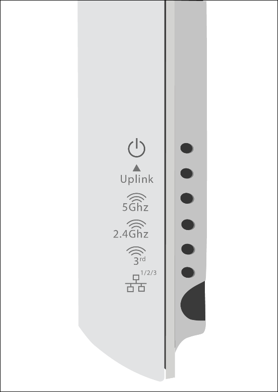
The following table indicates the device states based on the LEDs.
| LED | Status | Description |
|---|---|---|
| Power | Solid Green | Power ON |
| OFF | Power OFF | |
| Uplink | Solid Green | Device connected through WAN port (Ethernet port) at 10/100/1000 Mbps |
| Blinking Green | Activity on WAN port | |
| 5 GHz | Solid Green | No activity on 5 GHz radio |
| Blinking Green | Wireless activity on 5 GHz radio | |
| 2.4 GHz | Solid Green | No activity on 2.4 GHz radio |
| Blinking Green | Wireless activity on 2.4 GHz radio | |
| Radio 3 | Blinking Green | Activity on third radio |
| LAN1/2/3 | Solid Green | Device connected to LAN port 1/2/3 on the bottom of the device at 10/100/1000 Mbps |

| Port | Description | Connector Type | Speed/Protocol |
|---|---|---|---|
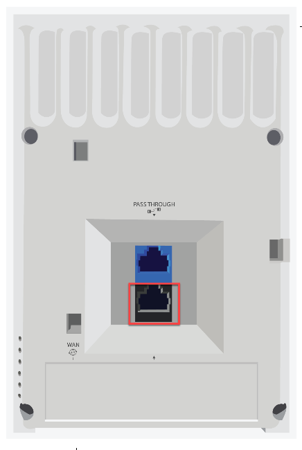
| PASSTHROUGH | This is a wired port that facilitates extension of the wired network after the AP is mounted on the wall. Another device can be plugged in to the pass-through port on the bottom of the W-118 device. The traffic on the pass-through port does not interfere with the AP traffic. No policies can be applied on the pass-through port traffic. | RJ45 | - |
| WAN | Enables you to connect the device to a wired LAN through a switch or a hub. The device can then communicate with the server. This port also provides the power for the device using the 802.3af standard | RJ45 | 10/100/1000 Mbps Ethernet Power over Ethernet |
| Port | Description | Connector Type | Speed/Protocol |
|---|---|---|---|
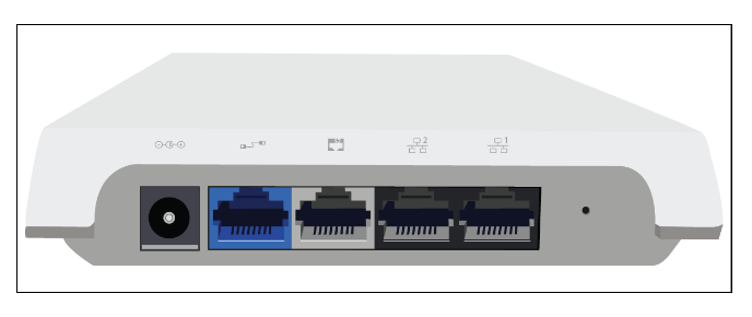
| DC IN | Enables you to connect to and power on device using 12 V DC power with 2 ampere. | 5.5mm overall diameter/2.1mm center pin/hole | -- |
| Pass-through port | The pass-through port is used to plug in a device into another wired port that is available on the wall where the AP is installed. The pass-through port at the rear of the device and pass-through port on the bottom of the device are internally connected. | RJ45 | -- |
| Ethernet (LAN3/PSE) | Gigabit Ethernet port that can be used for wired extension for an SSID. This port also provides the power for the device using the 802.3af standard | RJ45 | 10/100/1000 Mbps Gigabit Ethernet |
| Ethernet (LAN2) | Gigabit Ethernet port that can be used for wired extension for an SSID. | RJ45 | 10/100/1000 Mbps Gigabit Ethernet |
| Ethernet (LAN1) | Gigabit Ethernet port that can be used for wired extension for an SSID. | RJ45 | 10/100/1000 Mbps Gigabit Ethernet |
| Reset | Resets the W-118 device to factory defaults. To reset the device, press and hold the Reset Pin Hole until all LEDs go off which indicates that the device has rebooted. Pressing the Reset Pin Hole while the device is booting up will not have any effect. You should perform this operation only when the device is running. | Pin hole push button | Hold down and power cycle the device to reset |
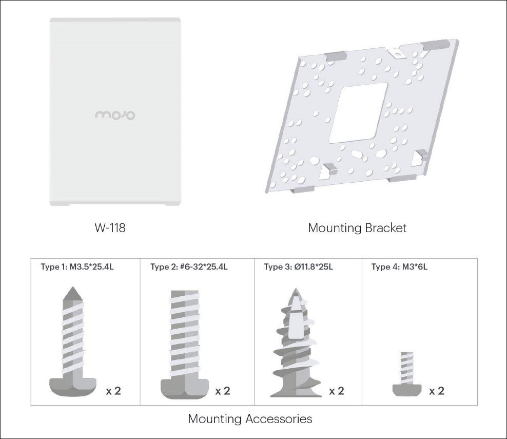
If the package is not complete, please contact the Arista Networks Technical Support Team at This email address is being protected from spambots. You need JavaScript enabled to view it., or return the package to the vendor or dealer where you purchased the product.
This installation guide explains how to deploy the W-118 access point (AP).
Installing the AP constitutes your acceptance of the terms and conditions of the EULA mentioned above in this document.
This guide can be referred by anyone who wants to install and configure the W-118 access point.
To receive important news on product updates, please visit our website at https://www.arista.com/en/support/product-documentation. We continuously enhance our product documentation based on customer feedback.
www.arista.com
DOC-03485-03
|
Headquarters
5453 Great America Parkway
Santa Clara, CA 95054, USA +1-408 547-5500 www.arista.com
|
Support
+1-408 547-5502
+1-866 476-0000 This email address is being protected from spambots. You need JavaScript enabled to view it.
|
Sales
+1-408 547-5501
+1-866 497-0000 This email address is being protected from spambots. You need JavaScript enabled to view it.
|