Appendix B: Product Compliance

Singapore IMDA Registration Mark


Appendix A: AP-Server Mutual Authentication

The AP-server communication begins with a mutual authentication step in which the AP and server authenticate each other using a shared secret. The AP-server communication takes place only if this authentication succeeds.

After the authentication succeeds, a session key is generated. From this point on, all communication between the AP and server is encrypted using the session key.

The AP and server are shipped with the same default value of the shared secret. Both the server and the AP have CLI commands to change the shared secret.

Note: After the shared secret (communication key) is changed on the server, all APs connected to the server will automatically be set up to use the new communication key.You must manually configure the new communication key on an AP if it is not connected to the server when the key is changed on the server.
Note:Although the server is backward compatible—that is, older version APs can connect to a newer version server—this is not recommended.

Access Point Troubleshooting

The table below lists some of the troubleshooting guidelines for the access point (AP).
Problem Solution
The AP did not receive a valid IP address via the DHCP. Ensure that the DHCP server is on and available on the VLAN/subnet to which the AP is connected. If the AP still fails to get a valid IP address, you can reboot it to see if the problem is resolved.
Unable to connect to the server.
  • Ensure that the server is running and is reachable from the network to which the AP is connected. If a firewall or a router has Access Control Lists (ACLs) enabled between the AP and the server, ensure that traffic on UDP port 3851 is allowed.
  • Use the IP-based server discovery method and ensure that you have correctly entered the DNS name, wifi-security-server , on the DNS server.
  • Ensure that the DNS server IP addresses are either correctly configured, or are provided by the DHCP server.
  • The AP might fail to authenticate with the server. In this case, an 'Authentication failed ' event is raised on the server. Refer to the event for recommended action.
The AP has encountered a problem.
  • If you are using Arista Cloud Services, then open the TCP port 443 (SSL). If you have an on-premises installation, then open UDP port 3851 and port 80.
  • If you are using a Proxy, Web Accelerator, or URL Content Filter between the AP and the Internet, ensure that the settings allow communication between the AP and Arista Cloud Services.
  • If your configuration requires you to specify an exact IP address or IP range for Arista Cloud Services, please contact This email address is being protected from spambots. You need JavaScript enabled to view it..

Install the Access Point

This chapter contains the stepwise procedure to install the access point (AP).

Zero-Configuration of the Access Point

Zero-configuration is supported under the following conditions:

  • The device is in AP mode with background scanning on and no SSID configured.

  • A DNS entry wifi-security-server is set up on all the DNS servers. This entry should point to the IP address of the server. By default, the AP looks for the DNS entry wifi-security-server.

  • The AP is on a subnet that is DHCP enabled.

Important: If the AP is on a network segment that is separated from the server by a firewall, you must first open port 3851 for bidirectional User Datagram Protocol (UDP) and Transport Control Protocol (TCP) traffic on that firewall. This port number is assigned to Arista Networks. Zero-configuration cannot work if multiple APs are set up to connect to multiple servers. In this case, the APs must be configured manually. For details on how to configure an AP manually, see the Access Point Configuration Guide on our website at https://www.arista.com/en/support/product-documentation .

Take a configured AP; that is, ensure that a static IP is assigned to the AP or the settings have been changed for DHCP. Note the MAC address and the IP address of the AP in a safe place before it is installed in a hard-to-reach location. The MAC address of the AP is printed on a label at the bottom of the product.

The steps to install the AP with no configuration (zero-configuration) are as follows:

  1. Ceiling Mount the AP or Wall Mount the AP.
  2. Connect the AP to the network.
  3. Power ON the AP.

Ceiling Mount the Access Point

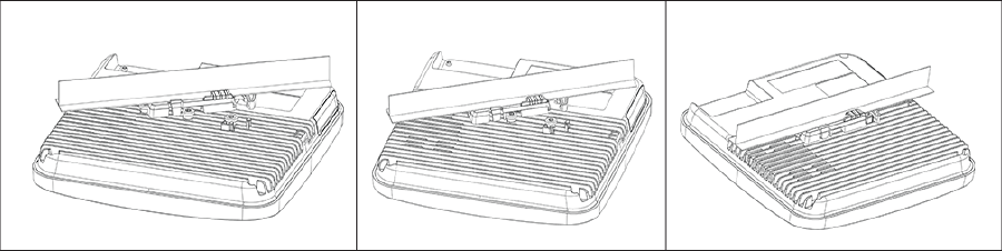
Mounting the access point (AP) on the ceiling consists of the following steps:

  1. Affix the bracket to the T -grid: Use the mounting bracket to install the AP on the ceiling. Fix the bracket to the T-grid and rotate the bracket so that it snaps on the T-grid. The bracket is now parallel to an arm of the T-grid. Ensure that the bracket is properly snapped to the T-grid, as shown below.
  2. Mounting C-360 on the bracket: Place the first mounting post on the rear-side of the AP on to the lower notch of the bracket. Rotate the AP such that the center mounting post fits in to the center notch on the bracket. Ensure that all the mounting posts on the rear-side of the AP are snapped in to the respective notches on the bracket. The mounting posts now properly fit in the respective notches of the bracket and the AP is mounted properly.
    Mounting Instructions using the Silhouette/Interlude Bracket Mount: The Silhouette/Interlude mounting bracket is not a part of the standard package and must be procured separately. The mounting instructions for the Silhouette/Interlude Bracket Mount are similar to the Standard Package Content's mounting instructions.
    Note: You should label the APs using MAC addresses or your own convention. For example, use serial numbers, so that you can easily identify the APs.

Wall Mount the Access Point

Note: The wall mounting accessory SKU can be ordered and purchased separately.

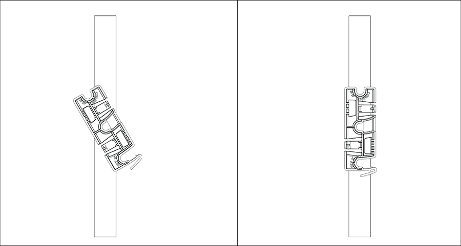
For instructions on wall mounting the access point, refer to Wall Mount the Access Point article.

Power the Access Point On

You can power the access point (AP) on by plugging one end of the Ethernet cable into the PoE switch or injector and the other end into the Ethernet/PoE port on the AP. Ensure the PoE source you are using is turned on.

As an alternative to PoE, you can insert a compatible power adaptor plug into an AC power outlet and the other end into the power input port on the AP.

Note: If you are not using PoE, ensure that you use only an AC power adaptor supported by the AP.

Using the C-360 with Power Adapter

To power up the device with power adapter, perform the following steps:
  1. Plug the power cable into the DC power receptacle at the rear of the device.
  2. Plug the other end of the power cable into an 110V~240V 50/60 Hz AC power source.
  3. Wait until the device is ready. Refer to the LED status table.

Connect the Access Point to the Network

To connect the access point (AP) to the network, perform the following steps:
  1. Ensure that a DHCP server is available on the network to enable network configuration of the AP.
  2. Add the DNS entry wifi-security-server on all DNS servers. This entry must point to the IP address of the server.
  3. Ensure that DHCP is running on the subnet to which the AP is connected.
  4. Check the LEDs on the AP to ensure that it is connected to the server.
  5. Log on to the server using ssh and run the get sensor list command.

    You will see a list of all Arista devices that are recognized by the server. Single Sign-On users can go to the Monitor tab in CloudVision Cognitive Unified Edge and check whether the device is visible under the Monitor tab.

The AP is connected and operational.
Note:If zero configuration fails, the AP must be configured manually.
Important:If DHCP is not enabled on a subnet, the AP cannot connect to that subnet with zero-configuration. If the DNS entry is not present on the DNS servers, or if you do not have the DHCP server running on the subnet, you must manually configure the AP. For details on configuring an AP manually, see the Access Point Configuration guide on our website at https://www.arista.com/en/support/product-documentation .

Connect the Access Point using PoE

If you are using a PoE injector, make sure the data connection is plugged into a suitable switch port with proper network connectivity.

For PoE port details, see the Rear Panel section.

Access Point Overview

C-360 is a tri-radio 802.11ax access point.

This chapter provides an overview of the C-360 access point (AP) and describes:

Front Panel

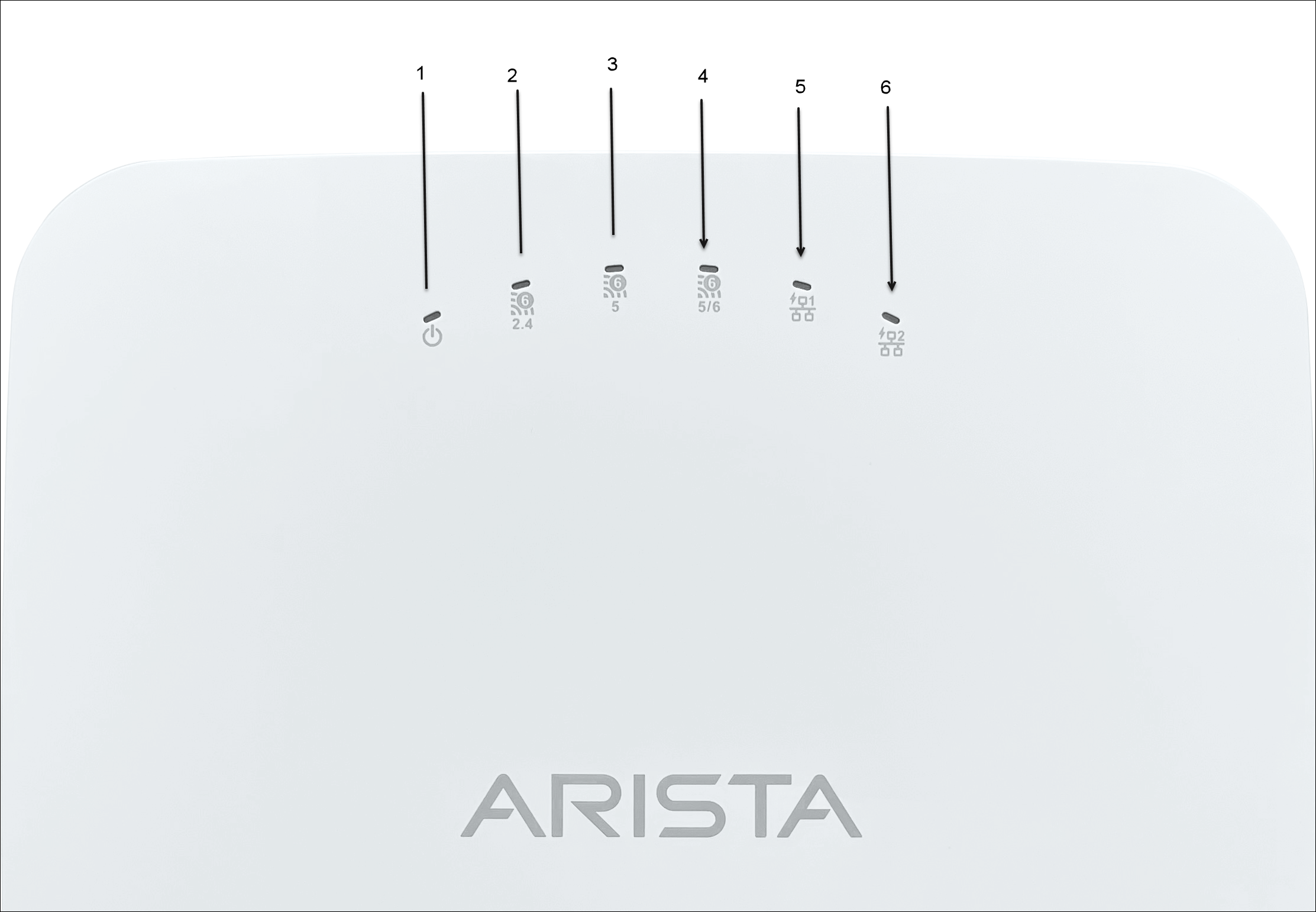
The front panel of the C-360 has 6 LEDs that indicate the status of various device functions.

Figure 1. Front Panel LEDs

Table 1. Labels: Front Panel LEDs
Label Description
1 Power
2 2.4 GHz Radio
3 5 GHz Radio
4 Third Radio - 5/6 GHz
5 LAN1
6 LAN2

Power LED: The following table describes the Power LED states.

Table 2. Power LED States Description
  Green Orange
Solid Running at full capability Running at reduced capability
Blinking Received IP address, but not connected to the server Did not receive an IP address

Reduced capability indicates that the AP is getting lower than the required maximum power from the PoE switch, i.e., 802.3at instead of 802.3bt.

LAN1 LED: ON when the corresponding interface is up.

LAN2 LED: ON when the corresponding interface is up and either wired guest or link aggregation is configured.

Radio LEDs: ON when the corresponding radio is operational.

Rear Panel

The rear panel of the AP has its DC power port and 802.3bt compliant PoE LAN ports to power the device and connect it to a wired LAN.
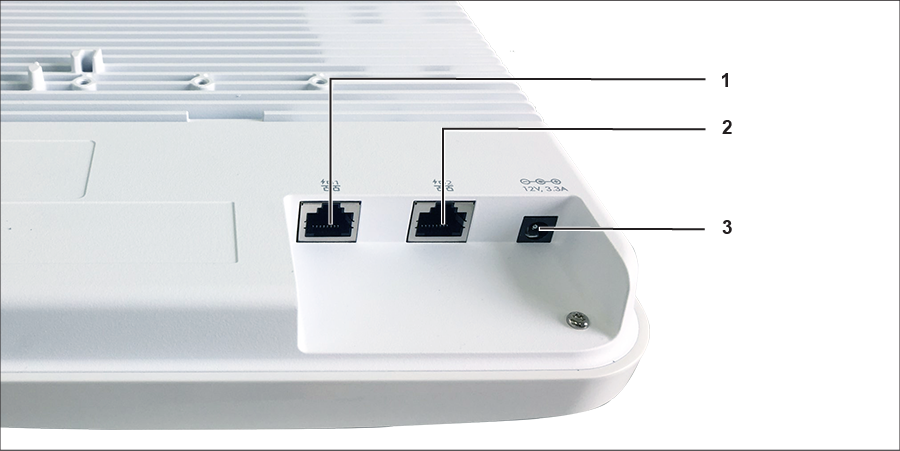
Figure 2. Rear Panel
Table 3. Labels: Rear Panel
Label Description
1 LAN1
2 LAN2
3 Power

The following tables shows port details for C-360.

 
Port Description Connector Type Speed/Protocol
Power 12V DC 5.5 mm overall diameter / 2.1 mm center pinhole N/A
LAN 1 10 Gigabit Ethernet with 802.3bt compliant PoE RJ-45 100 / 1000 Mbps / 2.5 / 5 / 10 Gbps Ethernet
LAN 2 10 Gigabit Ethernet with 802.3bt compliant PoE RJ-45 100 / 1000 Mbps / 2.5 / 5 / 10 Gbps Ethernet

Side Panel

The side panel of the AP has a console port, a USB port, and a Reset pin.
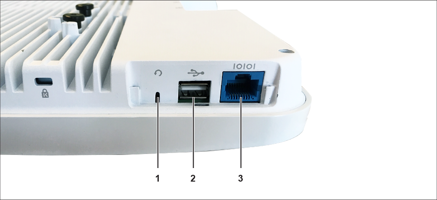
Figure 3. Side Panel
Table 4. Labels: Side Panel
Label Description
1 Reset
2 USB
3 Console
Port Description Connector Type Speed/Protocol
Console

Establish ‘config shell’ terminal session via serial connection

RJ-45
  • RS 232 Serial (115200 bits per second)
  • Data bits:8; Stop bits: 1
  • Parity: None
  • Flow Control: None
USB USB 3.0 port USB Type-A Future Use
Reset

Reset to factory default settings port. Hold down and power cycle the device to reset.

Pinhole push button N/A

When you reset the AP, the following settings are reset:
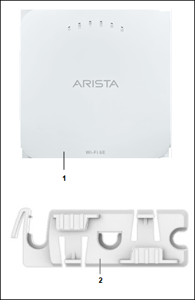
  • Config shell password is reset to config.
  • Server discovery value is erased and changed to the default, redirector.online.spectraguard.net (primary) and wifi-security-server (secondary).
  • All the VLAN configurations are lost.
  • If a static IP is configured on the AP, the IP address is erased and DHCP mode is set. The factory default IP address of the AP is 169.254.11.74.

Package Content

The AP package must contain the components shown in the following figure.
Figure 1. Package Components
Table 1. Labels: Package Components
Label Description
1 C-360 Access Point
2 15/16" (24 mm) Mounting Bracket
Important: The MAC address of the AP is printed on a label at the bottom of the product and the packaging box. Note down the MAC address before mounting the AP on the ceiling or at a location that is difficult to access.

If the package is not complete, please contact the Arista Networks Technical Support Team at This email address is being protected from spambots. You need JavaScript enabled to view it. or return the package to the vendor or dealer where you purchased the product.

About This Guide

This installation guide explains how to deploy the C-360 access point (AP).

Important:Please read the EULA before installing the access point (AP). You can download and read the EULA from https://www.arista.com/en/support/product-documentation.

Installing the AP constitutes your acceptance of the terms and conditions of the EULA mentioned above.

Intended Audience

This guide can be referred by anyone who wants to install and configure the access point.

Document Overview

Note:All instances of the term 'server' in this document refer to the Wireless Manager, unless the server name or type is explicitly stated.

Product and Documentation Updates

To receive important news on product updates, please visit our website at https://www.arista.com/en/support/product-documentation. We continuously enhance our product documentation based on customer feedback

This telecommunication equipment conforms to the technical standards or requirements of NBTC.

Quick Start Guide
C-360 Access Point
Arista Networks

www.arista.com

DOC-05349-01

Headquarters
5453 Great America Parkway
Santa Clara, CA 95054, USA
+1-408 547-5500
www.arista.com
Support
+1-408 547-5502
+1-866 476-0000
This email address is being protected from spambots. You need JavaScript enabled to view it.
Sales
+1-408 547-5501
+1-866 497-0000
This email address is being protected from spambots. You need JavaScript enabled to view it.
© Copyright 2022 Arista Networks, Inc. The information contained herein is subject to change without notice. Arista Networks and the Arista logo are trademarks of Arista Networks, Inc., in the United States and other countries. Other product or service names may be trademarks or service marks of others.