Product Compliance
www.arista.com
DOC-06000-02
|
Headquarters
5453 Great America Parkway
Santa Clara, CA 95054, USA +1-408 547-5500 www.arista.com
|
Support
+1-408 547-5502
+1-866 476-0000 This email address is being protected from spambots. You need JavaScript enabled to view it.
|
Sales
+1-408 547-5501
+1-866 497-0000 This email address is being protected from spambots. You need JavaScript enabled to view it.
|
This guide is intended for properly trained service personnel and technicians who need to install selected Arista Networks appliances.
The following topics are covered in this section:
This guide is intended for properly trained service personnel and technicians who need to install the following Arista appliance:
CCA-ETM-Q6
Only qualified personnel should install, service, or replace this equipment.
Seul le personnel qualifié doit installer, service, ou remplacer cet équipement.
Upon receiving the appliance, inspect the shipping boxes and record any external damage. Retain packing materials if you suspect that part of the shipment is damaged; the carrier may need to inspect them.
If the boxes were not damaged in transit, unpack them carefully. Ensure that you do not discard any accessories that may be packaged in the same box as the main unit.
Inspect the packing list and confirm that you received all listed items. Compare the packing list with your purchase order. Parts List provides a list of components included with the appliance.
Refer to the Arista Networks document Safety Information and Translated Safety Warnings available at: https://www.arista.com/en/support/product-documentation.
Any customer, partner, reseller, or distributor holding a valid Arista Service Contract can obtain technical support in any of the following ways:
A support case may be created through the support portal on our website. You may also download the most current software and documentation, as well as view FAQs, Knowledge Base articles, Security Advisories, and Field Notices.
No user serviceable parts inside. Refer all servicing to qualified service personnel.
Aucune pièce réparable par l'utilisateur à l'intérieur. Confiez toute réparation à un technicien qualifié.
| Appliance | Size (W x D x H) | Weight |
|---|---|---|
| CCA-ETM-Q6 | 438mm x 300mm x 44mm | 4.98kg |
| Appliance | Operating Temperature | Storage Temperature | Operating Altitude | Relative Humidity |
|---|---|---|---|---|
| CCA-ETM-Q6 | 0°C to 40°C | -10°C to 70°C | Sea level to 2000 meters for Operations, 3000 meters for Storage | 20 to 85% for Operations, 5 to 90% for Storage |
| Power Source | Ratings |
|---|---|
| AC INPUT - 250W PSU | 100-240V,1.5-2.5A, 50-60Hz |
The following topics are covered in this section:
The following criteria should be considered when selecting a site to install the appliance.
Pour empêcher l’interrupteur de surchauffe, ne pas utiliser il dans une zone où la température ambiante est supérieure à 40°C (104°F).
When mounting the appliance in a partially filled rack, load the rack from bottom to top, with the heaviest equipment at the bottom. Load the appliance at the bottom if it is the only item in the rack.
Toutes les connexions d’alimentation doivent être enlevées pour hors tension l’appareil.
The following tools are required for installation:
Installation de cet équipement doit être conformes aux codes électriques locaux et nationaux. Si nécessaire, consulter les organismes de réglementation appropriés et des autorités de contrôle pour assurer la conformité.
Lire toutes les instructions d’installation avant de brancher le système à la source d’alimentation.
Cet équipement doit être mis à la terre. Ne jamais modifier le conducteur de terre.
Rear Panel displays the location of the power supply on the rear panel of the appliance.
Connect an Ethernet cable from your management computer or LAN switch to port 1.
You can manage your appliance via Edge Threat Management Dashboard or from the local network.
Navigate your web browser to https://edge.arista.com/cmd.
Log in with your Edge Threat Management Dashboard account, or click Create Account to set up an account.
Navigate to the Appliances screen and click Add.
Enter the serial number located on the bottom of your appliance.
Connect an Ethernet cable from your management computer or LAN appliance to the LAN port.
From your management computer, check the network status of your system and confirm that you receive an IPv4 address in the subnet of 192.168.2.0/24 (e.g. 192.168.2.100).
In a browser, navigate to http://192.168.2.1.
Follow the steps in your browser to complete the setup.
The following topics are covered in this appendix:
Front panel indicators are located on the left display screen and the right LED indicators.
The figure below shows the front panel indicators and their locations.
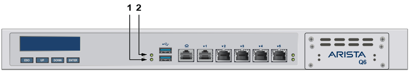
| 1 | Power |
| 2 | HDD status |
Port LEDs, located in the vicinity of their corresponding ports, provide link and operational status.
The following figure displays the Port LED location on the Q6 appliance.
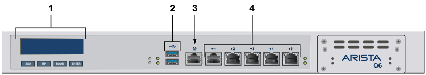
| 1 | Screen display | 3 | WAN port |
| 2 | USB ports | 4 | Ethernet ports |
The following parts are included:
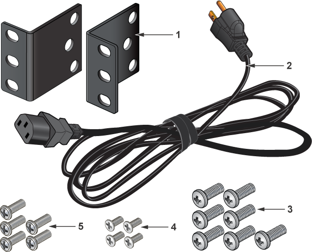
| 1 | Rack Mount Ears | 4 | M2 Screws |
| 2 | Power Cable | 5 | M3 Screws |
| 3 | M4 Screws |
This appendix displays the rear panel of all appliances covered by this guide.

| 1 | Fans | 4 | Power switch |
| 2 | HDMI port | 5 | PSU fan |
| 3 | Power cord port |
This appendix covers the Regulatory Model Number for the appliance in this guide.
| Regulatory Model Number(RMN) | Product Number(s) |
|---|---|
| AN2202, CAR-2070-5620-E90 | CCA-ETM-Q6 |