Appendix B: Product Compliance
Singapore IMDA Registration Mark
Singapore IMDA Registration Mark
The AP-server communication begins with a mutual authentication step where the AP and server authenticate each other using a shared secret. The AP-server communication takes place only if this authentication succeeds.
After the authentication succeeds, the server generates a session key and encrypts all communication between the AP and theserver using the session key.
The AP and server ship with the same default value for the shared secret. Use the CLI commands on the server and the AP to change the shared secret.
For more information on the AP-server communication process, see the Wi-Fi Access Point Server Communication Workflow article.
| Problem | Solution |
|---|---|
| The AP did not receive a valid IP address via the DHCP. | Be sure that the DHCP server is on and available on the VLAN/subnet connected to the AP. If the AP fails to get a valid IP address, you can reboot it to see if that resolves the problem. |
| Unable to connect to the server. |
|
| The AP has encountered a problem. |
|
If using a PoE injector, plug the data connection into a suitable switch port with proper network connectivity.
For PoE port details, see the Rear Panel section.
Power on the access point (AP) by plugging one end of the Ethernet cable into the PoE+ (802.3at) switch or injector and the other end into the LAN1 PoE+ port on the AP. Be sure to turn on the PoE+ source or use a compatible power adapter (Arista SKU: PWR-AP-W3) to power the AP. The power adapter must be connected to a socket outlet with an earthing connection.
Use a compatible power adapter (Arista SKU: PWR-AP-W3) to power the AP.
Warning: C-400 is intended to be supplied by approved external power source (UL listed/ IEC 60950-1/IEC 62368-1) whose output complies with ES1/SELV, PS2/LPS, output rating 12V DC, 2A minimum (for DC port) or 54V DC, 0.6A minimum (for PoE port), at an ambient temperature of 45°C, and at maximum altitude of 5000m. For any assistance, please contact your Arista representative. For C-400P, use the power adater provided in the packaged contents.
The maximum altitude of operation for the power adapter is 5000m.
To power up the device with a power adapter, perform the following steps:This chapter contains the procedure to install the access point (AP).
The AP supports zero-configuration under the following conditions:
Assign a static IP address to the AP or change the settings to DHCP. Make a note of the AP MAC address and the IP address in a safe place before installing it in a hard-to-reach location. Locate the AP MAC address on a label at the bottom of the product.
Use the following steps to install the AP with zero-configuration:
Mounting the access point (AP) on the ceiling consists of the following steps:
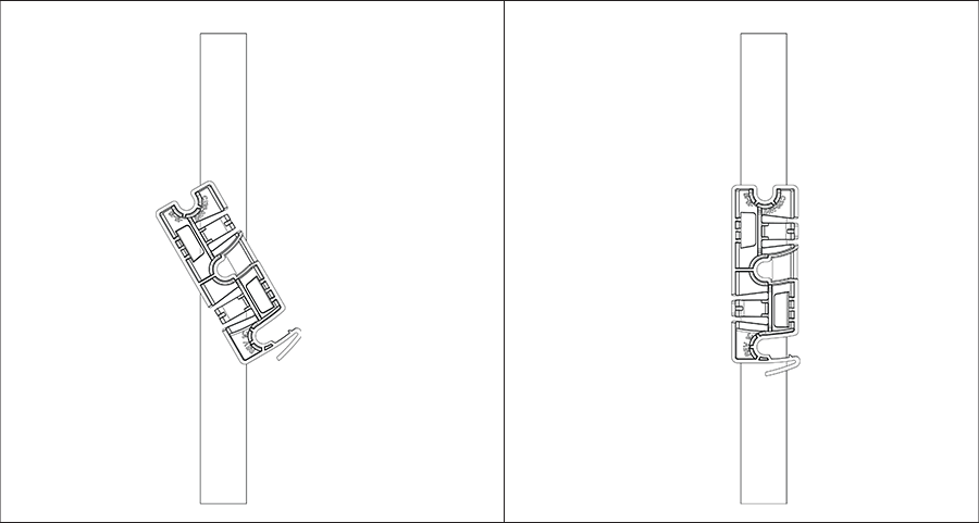
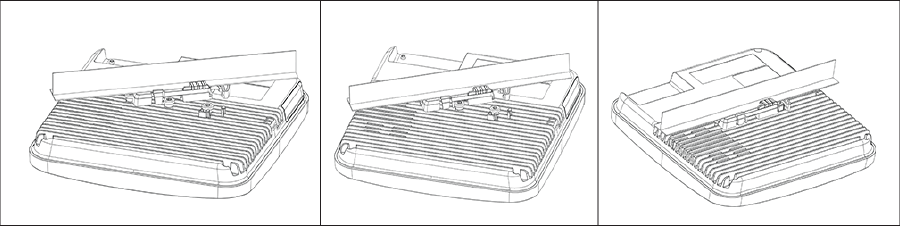
For instructions on wall mounting the access point, refer to Wall Mount the Access Point article.
C-400/C-400P is a Wi-Fi 7 multi-radio 802.11be access point. Refer to the datasheet for more information.
The front panel of the AP has 6 LEDs that indicate the status of various AP functions.
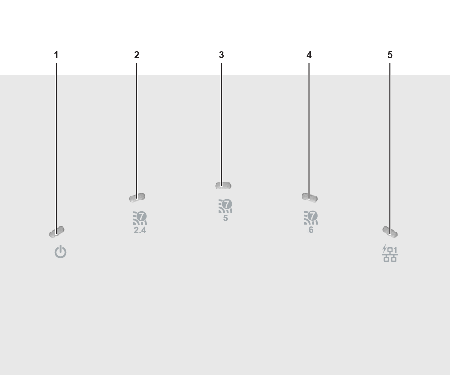
| 1 | Power | 2 | 2.4 GHz Radio | 3 | 5 GHz Radio |
| 4 | 6 GHz Radio | 5 | LAN1 |
Power LED: The following table describes the Power LED indicator states.
| Green | Orange | |
|---|---|---|
| Solid | Running at full capability | Running at reduced capability |
| Blinking | Received IP address, but not connected to the server | Did not receive an IP address |
Reduced capability indicates that the AP receives less than the required maximum power from the PoE+ switch. The AP receives 802.3af instead of 802.3at.
LAN1 LED: ON when the corresponding interface UP.
Radio LEDs: ON when the corresponding radio is operational.
The rear panel of the AP has a DC power port and a 802.3at compliant PoE+ LAN port to power the AP and connect it to a wired LAN.
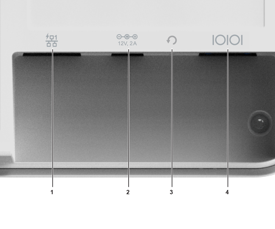
| 1 | LAN1, POE+ | 2 | DC Power |
| 3 | Reset | 4 | Console |
| Port | Description | Connector Type | Speed/Protocol |
|---|---|---|---|
| Power | 12V DC/2A | 5.5 mm overall diameter / 2.1 mm center pinhole | N/A |
| LAN 1 | 5 Gigabit Ethernet with 802.3at compliant PoE | RJ-45 | 100 /1000 Mbps / 2.5/ 5 Gbps Ethernet |
| Reset |
Reset to factory default settings port. Hold down and power cycle the device to reset. |
Pin hole push button | NA |
| Console |
Establish a ‘config shell’ terminal session through a serial connection |
RJ-45 | NA |
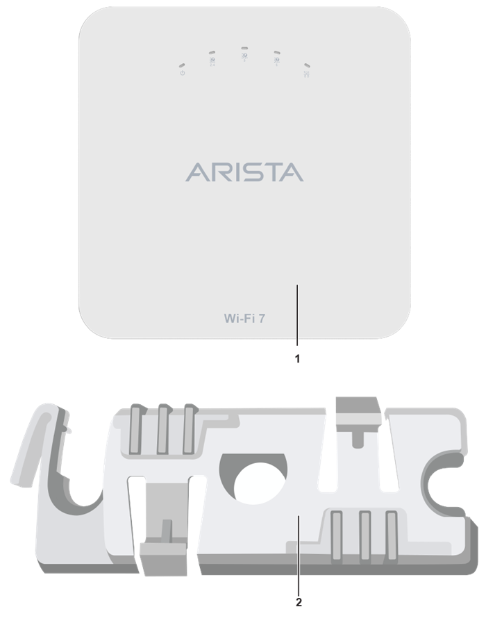
| 1 | C-400 or C-400P Access Point | 2 | 15/16" (24 mm) Mounting Bracket (MNT-AP-24MM) |
If you don't have a complete package, please contact the Arista Networks Technical Support Team at This email address is being protected from spambots. You need JavaScript enabled to view it. or return the package to the vendor or dealer where you purchased the product.
This installation guide explains how to deploy the C-400/C-400P access point (AP).
Installing the AP constitutes your acceptance of the terms and conditions of the EULA mentioned above.
This guide can be referred to by anyone installing and configuring the access point.
To receive important news on product updates, please visit our website at Arista Product Documentation. We continuously enhance our product documentation based on customer feedback.
www.arista.com
DOC-07780-01
|
Headquarters
5453 Great America Parkway
Santa Clara, CA 95054, USA +1-408 547-5500 www.arista.com
|
Support
+1-408 547-5502
+1-866 476-0000 This email address is being protected from spambots. You need JavaScript enabled to view it.
|
Sales
+1-408 547-5501
+1-866 497-0000 This email address is being protected from spambots. You need JavaScript enabled to view it.
|