
Virtual Edge Deployment

Standard hypervisors host the Virtual Edge as a virtual machine. This section discusses the prerequisites and the installation procedure for deploying a VeloCloud Virtual Edge on KVM and ESXi hypervisors.

This topic contains the following sections:

Deployment Prerequisites for Virtual Edge

This section discusses the requirements for Virtual Edge deployment.

Virtual Edge Requirements

Observe the following requirements before deploying a Virtual Edge:
  • The Virtual Edge must support 2, 4, 8, and 10 vCPU assignment.
    Table 1. Virtual Edge Requirements
      2 vCPU 4v CPU 8 vCPU 10 vCPU
    Minimum Memory (DRAM) 8 GB 16 GB 32 GB 32 GB
    Minimum Storage (Virtual Disk) 8 GB 8 GB 16 GB 16 GB
  • AES-NI CPU capability must pass to the Virtual Edge appliance.
  • The Virtual Edge must support up to 8 vNICs (the default is GE1 and GE2 LAN ports and GE3-GE8 WAN ports).
    Note: The deployment does not support over-subscription of Virtual Edge resources such as CPU, memory, and storage.
Table 2. Recommended Server Specifications
NIC Chipset Hardware Specification
Intel 82599/82599ES HP DL380G9 HP DL 380 Datasheet
Intel X710/XL710 Dell PowerEdge R640 Dell PowerEdge R640
  • CPU Model and Cores - Dual Socket Intel(R) Xeon(R) Gold 5218 CPU @ 2.30GHz with 16 cores each
  • Memory - 384 GB RAM
Intel X710/XL710 Supermicro SYS-6018U-TRTP+ Supermicro SYS-6018U-TRTP+
  • CPU Model and Cores - Dual Socket Intel(R) Xeon(R) CPU E5-2630 v4 @ 2.20GHz with 10 Cores each
  • Memory - 256 GB RAM


Table 3. Recommended NIC Specifications
Hardware Manufacturer Firmware Version Host Driver for Ubuntu 20.04.6 Host Driver for Ubuntu 22.04.2 Host Driver for ESXi 7.0U3 Host Driver for ESXi 8.0U1a
Dual Port Intel Corporation Ethernet Controller XL710 for 40GbE QSFP+ 7.10 2.20.12 2.20.12 1.11.2.5 and 1.11.3.5 1.11.2.5 and 1.11.3.5
Dual Port Intel Corporation Ethernet Controller X710 for 10GbE SFP+ 7.10 2.20.12 2.20.12 1.11.2.5 and 1.11.3.5 1.11.2.5 and 1.11.3.5
Quad Port Intel Corporation Ethernet Controller X710 for 10GbE SFP+ 7.10 2.20.12 2.20.12 1.11.2.5 and 1.11.3.5 1.11.2.5 and 1.11.3.5

Supported Operating Systems

  • Ubuntu Linux Distribution:
    • Ubuntu 20.04.6 LTS
    • Ubuntu 22.04.2 LTS
  • ESXi:
    • ESXi 7.0 U3 with vSphere Web Client 7.0.
    • ESXi 8.0 U1a with vSphere Web Client 8.0.

Firewall/NAT Requirements

If the Virtual Edge deploys behind a Firewall or a NAT device, the following requirements apply:
  • The Firewall must allow outbound traffic from the Virtual Edge to TCP/443 (for communication with the Orchestrator).
  • The Firewall must allow traffic outbound to Internet on ports UDP/2426 (VCMP).

CPU Flags Requirements

For detailed information about CPU flags requirements to deploy Virtual Edge, see Special Considerations for Virtual Edge Deployment.

Special Considerations for Virtual Edge Deployment

This section discusses the special considerations for Virtual Edge deployment.
  • The SD-WAN Edge is a latency-sensitive application. Refer to the Arista Documentation to adjust the Virtual Machine (VM) as a latency-sensitive application.
  • Recommended Host settings:
    • BIOS settings to achieve highest performance:
      • CPUs at 2.0 GHz or higher.
      • Enable Intel Virtualization Technology (Intel VT).
      • Deactivate Hyper-threading.
      • Virtual Edge supports paravirtualized vNIC VMXNET 3 and passthrough vNIC SR-IOV:
      • Deactivate power savings on CPU BIOS for maximum performance.
      • Activate CPU turbo.
      • CPU must support the AES-NI, SSSE3, SSE4, RDTSC, RDSEED, RDRAND instruction sets.
      • Arista recommends reserving 2 cores for Hypervisor workloads. For example, for a 10-core CPU system, run one 8-core virtual Edge or two 4-core virtual Edges and reserve 2 cores for Hypervisor processes.
    • For a dual socket host system, ensure the Hypervisor assigns network adapters, memory, and CPU resources within the same socket (NUMA) boundary as the assigned vCPUs.
  • Arista recommends the following VM settings:
    • CPU should be '100% reserved.'
    • CPU shares should be High.
    • Memory should be ‘100% reserved.’
    • Latency sensitivity should be High.
  • The default username for the SD-WAN Edge SSH console is root.

Cloud-init Creation

cloud-init is a Linux package responsible for handling early initialization of instances. If available in the distributions, it allows for configuration of many common parameters of the instance directly after installation. This creates a fully functional instance that the system configures based on a series of inputs.

The cloud-init configuration consists of two main configuration files: meta-data and user-data. The meta-data contains the network configuration for the Edge, and the user-data contains the Edge software configuration. Information within the cloud-init file identifies the Virtual Edge instance under installation.

The user-data can configure Cloud-init behavior. Users can provide the user-data at the time of launching the instance. A secondary disk in ISO format typically provides the configuration, which cloud-init detects during the first boot. This disk contains all early configuration data that apply at that time.

The Virtual Edge supports cloud-init and all essential configurations packaged in an ISO image.

Create the Cloud-init Meta-data and User-data Files

The final installation configuration options are set with a pair of cloud-init configuration files. The first installation configuration file contains the metadata. Create this file with a text editor and name it 'meta-data'. The data within this file identifies the Virtual Edge instance during installation. The instance-id can be any identifying name, and the local-hostname should be a host name that follows user's site standards.

  1. Create the meta-data file that contains the instance:
    • name.instance-id: vedge1
    • local-hostname: vedge1
  2. Add the network-interfaces section, shown below, to specify the WAN configuration. By default, all Edge WAN interfaces use DHCP. The configuration supports multiple interfaces.
    root@ubuntu# cat meta-data
    instance-id: Virtual-Edge
    local-hostname: Virtual-Edge
    network-interfaces:
          GE1:
             mac_address: 52:54:00:79:19:3d
          GE2:
             mac_address: 52:54:00:67:a2:53
          GE3:
             type: static
             ipaddr: 11.32.33.1
             mac_address: 52:54:00:e4:a4:3d
             netmask: 255.255.255.0
             gateway: 11.32.33.254
          GE4:
             type: static
             ipaddr: 11.32.34.1
             mac_address: 52:54:00:14:e5:bd
             netmask: 255.255.255.0
             gateway: 11.32.34.254
  3. Create the user-data file. This file contains three main modules: Orchestrator, Activation Code, and Ignore Certificates Errors.
    Table 4. Modules and Descriptions
    Module Description
    vco IP Address/URL of the Orchestrator.
    activation_code Activation code for the Virtual Edge. The system generates the activation code while creating an Edge instance on the Orchestrator.
    vco_ignore_cert_errors Option to verify or ignore any certificate validity errors.

    The system generates the activation code while creating an Edge instance on the Orchestrator.

    Important: There is no default password in Edge image. Provide the password in cloud-config:
    #cloud-config 
    password: passw0rd 
    chpasswd: { expire: False }
    ssh_pwauth: True
    velocloud:
          vce: 
                vco: 10.32.0.3 
                activation_code: F54F-GG4S-XGFI 
                vco_ignore_cert_errors: true 

Create the ISO File

After completing the files, package them into an ISO image. The virtual machine uses this ISO image as a virtual configuration CD. The following command creates this ISO image (called seed.iso in the below example) on a Linux system:
genisoimage -output seed.iso -volid cidata -joliet -rock user-data meta-data network-data

Including the network-interfaces section is optional. The system uses the DHCP option by default if the section is missing.

After generating the ISO image, transfer the image to a data store on the host machine.

Install Virtual Edge

Users can install Virtual Edge on KVM and ESXi using a cloud-init configuration file. The cloud-init configuration file contains interface configurations and the activation key of the Edge.

Ensure to create the cloud-init meta-data and user-data files, then package them into an ISO image file. For steps, see Cloud-init Creation.

KVM offers multiple ways to provide networking to virtual machines. Arista recommends the following options:
  • SR-IOV
  • Linux Bridge
  • OpenVSwitch Bridge
To enable SR-IOV:
To install Virtual Edge:

Activate SR-IOV on KVM

This procedure requires a specific NIC card. Arista certifies the following chip sets to work with the Gateway and Edge.
  • Intel 82599/82599ES
  • Intel X710/XL710
Note:
  • Before using the Intel X710/XL710 cards in SR-IOV mode on KVM, install the supported Firmware and Driver versions. Refer to Deployment Prerequisites for Virtual Edge.
  • The High Availability topology for the KVM Virtual Edge does not support SR-IOV mode. Disable SR-IOV for any KVM Edge pair in High Availability deployments.
To enable the SR-IOV mode on KVM, perform the following steps.
  1. Enable SR-IOV in the BIOS. Specific steps depend on the BIOS version. Log in to the BIOS console and look for SR-IOV Support/DMA. Verify support on the prompt by checking that Intel has the correct CPU flag.
    cat /proc/cpuinfo | grep vmx
  2. Add the options on Boot (in /etc/default/grub).
    GRUB_CMDLINE_LINUX="intel_iommu=on"
    1. Run the following commands: update-grub and update-initramfs -u.
    2. Reboot.
    3. Enable iommu.
      velocloud@KVMperf3:~$ dmesg | grep -i IOMMU
       [ 0.000000] Command line: BOOT_IMAGE=/vmlinuz-3.13.0-107-generic root=/dev/mapper/qa--multiboot--002--vg-root ro intel_iommu=on splash quiet vt.handoff=7 
       [ 0.000000] Kernel command line: BOOT_IMAGE=/vmlinuz-3.13.0-107-generic root=/dev/mapper/qa--multiboot--002--vg-root ro intel_iommu=on splash quiet vt.handoff=7 
       [ 0.000000] Intel-IOMMU: enabled
       ….
       velocloud@KVMperf3:~$ 
  3. Based on the NIC chip set used, add a driver as follows:
    • For Intel 82599/82599ES cards in SR-IOV mode:
      1. Download and install ixgbe driver from the Intel website.
      2. Configure ixgbe config (tar and sudo make install).
        velocloud@KVMperf1:~$ cat /etc/modprobe.d/ixgbe.conf
      3. If the ixgbe configuration file does not exist, create the file as follows.
        options ixgbe max_vfs=32,32
        options ixgbe allow_unsupported_sfp=1
        options ixgbe MDD=0,0
        blacklist ixgbevf
      4. Run the update-initramfs -u command and reboot the Server.
      5. Use the modinfo command to verify successful installation.
        velocloud@KVMperf1:~$ modinfo ixgbe and ip link
         filename: /lib/modules/4.4.0-62-generic/updates/drivers/net/ethernet/intel/ixgbe/ixgbe.ko
         version: 5.0.4
         license: GPL
         description: Intel(R) 10GbE PCI Express Linux Network Driver
         author: Intel Corporation, <このメールアドレスはスパムボットから保護されています。閲覧するにはJavaScriptを有効にする必要があります。>
         srcversion: BA7E024DFE57A92C4F1DC93
    • For the Intel X710/XL710 cards in SR-IOV mode:
      1. Download and install i40e driver from the Intel website.
      2. Create the Virtual Functions (VFs).
        echo 4 > /sys/class/net/device name/device/sriov_numvfs
      3. To make the VFs persistent after a reboot, add the command from the previous step to the /etc/rc.d/rc.local file.
      4. Deactivate the VF driver.
        echo “blacklist i40evf” >> /etc/modprobe.d/blacklist.conf
      5. Run the update-initramfs -u command and reboot the Server.

Validating SR-IOV (Optional)

Verify that the host machine has SR-IOV enabled by using the following command:
lspci | grep -i Ethernet
Verify the availability of Virtual Functions:
01:10.0 Ethernet controller: Intel Corporation 82599 Ethernet Controller Virtual Function(rev

Install Virtual Edge on KVM

This topic describes the procedure for installing and activating the Virtual Edge on KVM using a cloud-init configuration file.

For SR-IOV mode, enable SR-IOV on KVM. For steps, see Activate SR-IOV on KVM.
Note: The High Availability topology for the KVM Virtual Edge does not support SR-IOV mode. Disable SR-IOV for any KVM Edge pair in High Availability deployments.
To run Virtual Edge on KVM using libvirt:
  1. Use gunzip to extract the qcow2 file to the image location (for example, /var/lib/libvirt/images).
  2. Create the Network pools for the device using SR-IOV and OpenVswitch.

    Using SR-IOV:

    The following is a sample network interface template specific to Intel X710/XL710 NIC cards using SR-IOV.
        <interface type='hostdev' managed='yes'>
            <mac address='52:54:00:79:19:3d'/>
            <driver name='vfio'/>
            <source>
                <address type='pci' domain='0x0000' bus='0x83' slot='0x0a' function='0x0'/>
            </source>
            <model type='virtio'/>
        </interface>
    Using OpenVSwitch:
    <network>
      <name>passthrough</name>
      <model type='virtio'/>
      <forward mode="bridge"/>
      <bridge name="passthrough"/>
      <virtualport type='openvswitch'/>
      <vlan trunk='yes'>
        <tag id='33' nativeMode='untagged'/>
        <tag id='200'/>
        <tag id='201'/>
        <tag id='202'/>
      </vlan>
    </network>
    
    <network>
      <name>passthrough</name>
      <model type='virtio'/>
      <forward mode="bridge"/>
    </network>
    
    <domain type='kvm'>
      <name>vedge1</name>
      <memory unit='KiB'>4194304</memory>
      <currentMemory unit='KiB'>4194304</currentMemory>
      <vcpu placement='static'>2</vcpu>
      <resource>
        <partition>/machine</partition>
      </resource>
      <os>
        <type arch='x86_64' machine='pc-i440fx-trusty'>hvm</type>
        <boot dev='hd'/>
      </os>
      <features>
        <acpi/>
        <apic/>
        <pae/>
      </features>
      <!-- Set the CPU mode to host model to leverage all the available features on the host CPU -->
      <cpu mode='host-model'>
        <model fallback='allow'/>
      </cpu>
      <clock offset='utc'/>
      <on_poweroff>destroy</on_poweroff>
      <on_reboot>restart</on_reboot>
      <on_crash>restart</on_crash>
      <devices>
        <emulator>/usr/bin/kvm-spice</emulator>
        <!-- Below is the location of the qcow2 disk image -->
        <disk type='file' device='disk'>
          <driver name='qemu' type='qcow2'/>
          <source file='/var/lib/libvirt/images/edge-VC_KVM_GUEST-x86_64-2.3.0-18-R23-20161114-GA-updatable-ext4.qcow2'/>
          <target dev='sda' bus='sata'/>
          <address type='drive' controller='0' bus='0' target='0' unit='0'/>
        </disk>
        <!-- If using cloud-init to boot up virtual edge, attach the 2nd disk as CD-ROM -->
        <disk type='file' device='cdrom'>
          <driver name='qemu' type='raw'/>
          <source file='/home/vcadmin/cloud-init/vedge1/seed.iso'/>
          <target dev='sdb' bus='sata'/>
          <readonly/>
          <address type='drive' controller='1' bus='0' target='0' unit='0'/>
        </disk>
        <controller type='usb' index='0'>
          <address type='pci' domain='0x0000' bus='0x00' slot='0x01' function='0x2'/>
        </controller>
        <controller type='pci' index='0' model='pci-root'/>
        <controller type='sata' index='0'>
          <address type='pci' domain='0x0000' bus='0x00' slot='0x05' function='0x0'/>
        </controller>
        <controller type='ide' index='0'>
          <address type='pci' domain='0x0000' bus='0x00' slot='0x01' function='0x1'/>
        </controller>
        <!-- The first two interfaces are for the default L2 interfaces, NOTE VLAN support just for SR-IOV and OpenvSwitch -->
        <interface type='network'>
          <model type='virtio'/>
          <source network='LAN1'/>
          <vlan><tag id='#hole2_vlan#'/></vlan>
          <alias name='LAN1'/>
          <address type='pci' domain='0x0000' bus='0x00' slot='0x12' function='0x0'/>
        </interface>
        <interface type='network'>
          <model type='virtio'/>
          <source network='LAN2'/>
          <vlan><tag id='#LAN2_VLAN#'/></vlan>
          <alias name='hostdev1'/>
          <address type='pci' domain='0x0000' bus='0x00' slot='0x13' function='0x0'/>
        </interface>
        <!-- The next two interfaces are for the default L3 interfaces. Note that additional 6 routed interfaces are supported for a combination of 8 interfaces total -->
        <interface type='network'>
          <model type='virtio'/>
          <source network='WAN1'/>
          <vlan><tag id='#hole2_vlan#'/></vlan>
          <alias name='LAN1'/>
          <address type='pci' domain='0x0000' bus='0x00' slot='0x12' function='0x0'/>
        </interface>
        <interface type='network'>
          <model type='virtio'/>
          <source network='LAN2'/>
          <vlan><tag id='#LAN2_VLAN#'/></vlan>
          <alias name='hostdev1'/>
          <address type='pci' domain='0x0000' bus='0x00' slot='0x13' function='0x0'/>
        </interface>
        <serial type='pty'>
          <target port='0'/>
        </serial>
        <console type='pty'>
          <target type='serial' port='0'/>
        </console>
        <input type='mouse' bus='ps2'/>
        <input type='keyboard' bus='ps2'/>
        <graphics type='vnc' port='-1' autoport='yes' listen='127.0.0.1'>
          <listen type='address' address='127.0.0.1'/>
        </graphics>
        <sound model='ich6'>
          <address type='pci' domain='0x0000' bus='0x00' slot='0x04' function='0x0'/>
        </sound>
        <video>
          <model type='cirrus' vram='9216' heads='1'/>
          <address type='pci' domain='0x0000' bus='0x00' slot='0x02' function='0x0'/>
        </video>
        <memballoon model='virtio'>
          <address type='pci' domain='0x0000' bus='0x00' slot='0x06' function='0x0'/>
        </memballoon>
      </devices>
    </domain>


  3. Save the domain XML file that defines the VM (for example, vedge1.xml created in Step 2).
  4. Launch the VM by performing the following steps:
    1. Create VM.
      virsh define vedge1.xml
    2. Start VM.
      virsh start vedge1
    Note: The name element in the domain XML file defines the VM as vedge1. Replace vedge1 with the specific name used in the name element.
  5. When using SR-IOV mode, after launching the VM, set the following on the Virtual Functions (VFs) used:
    1. Set the spoofchk off.
      ip link set eth1 vf 0 spoofchk off
    2. Set the Trusted mode on.
      ip link set dev eth1 vf 0 trust on
    3. Set the VLAN, if necessary.
      ip link set eth1 vf 0 vlan 3500
    Note: Open vSwitch (OVS) mode bypasses the Virtual Functions configuration step.
  6. Console into the VM.
    virsh list
    Id Name State
    ----------------------------------------------------
    25 test_vcg running
    velocloud@KVMperf2$ virsh console 25
    Connected to domain test_vcg
    Escape character is ^]
The cloud-init already includes the activation key, generated while creating a new Virtual Edge on the Orchestrator. The cloud-init file configures the Virtual Edge with the specified settings. These settings configure the interfaces as the Virtual Edge powers up. After the Virtual Edge is online, it activates with the Orchestrator using the activation key. The cloud-init file defines the Orchestrator IP address and the activation key.

Activate SR-IOV on ESXi

This procedure requires a specific NIC card. Arista certifies the following chip sets to work with the Gateway.
  • Intel 82599/82599ES
  • Intel X710/XL710
Note: Before using the Intel X710/XL710 cards in SR-IOV mode, install the supported Firmware and Driver versions. Refer to Deployment Prerequisites for Virtual Edge.
Enabling SR-IOV on ESXi is an optional configuration. To enable SR-IOV on ESXi:
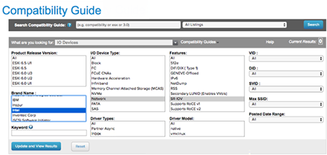
  1. Ensure the NIC supports SR-IOV. Check the Hardware Compatibility List (HCL) at Arista Documentation.
    • Brand Name: Intel
    • I/O Device Type: Network
    • Features: SR-IOV
    Figure 1. Compatibility Guide
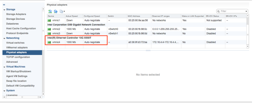
  2. Go to the specific Arista host, select the Configure tab, and then choose Physical adapters.
    Figure 2. Physical Adapters
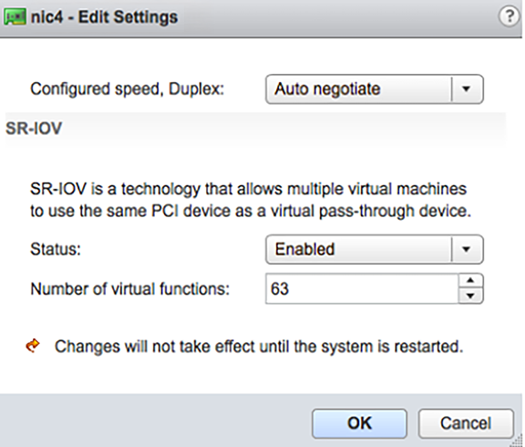
  3. Select Edit Settings. Change Status to Enabled and specify the number of required virtual functions. This number varies by the type of NIC card.
    Figure 3. Edit Settings
  4. Reboot the hypervisor.
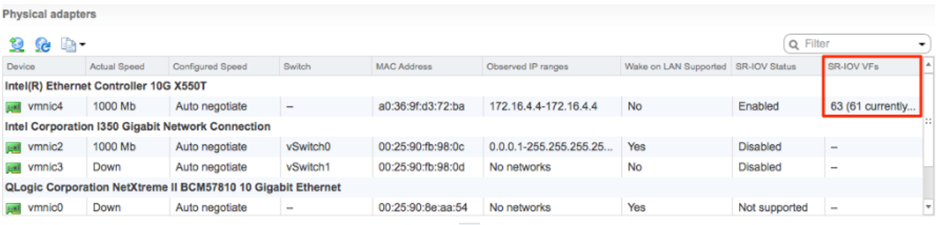
    A successful SR-IOV enablement displays the number of Virtual Functions (VFs) under the specified NIC, following an ESXi reboot.
    Figure 4. Virtual Functions List
    Note: To support VLAN tagging on SR-IOV interfaces, user must configure VLAN ID 4095 (Allow All) on the Port Group connected to the SR-IOV interface. For additional information, see VLAN Configuration.

Install Virtual Edge on ESXi

This topic describes the procedure for installing the Virtual Edge on ESXi.

Ensure to create the cloud-init meta-data and user-data files, then package them into an ISO image file. For steps, see Cloud-init Creation.

To use SR-IOV mode, enable SR-IOV on ESXi. For steps, see Activate SR-IOV on ESXi.

To install Virtual Edge on ESXi:

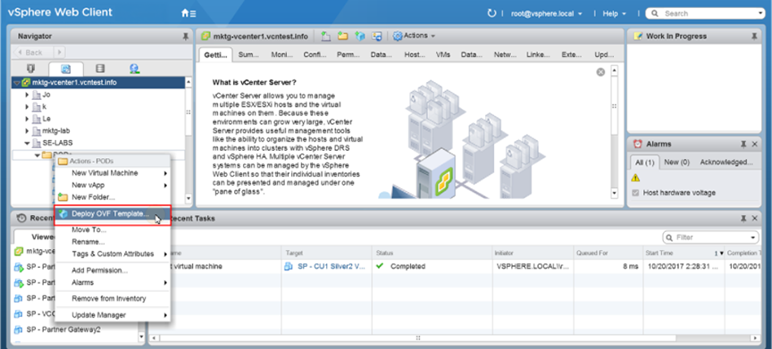
  1. Use the vSphere client to deploy an OVF template, and then select the Edge OVA file.
    Figure 5. vSphere Web Client
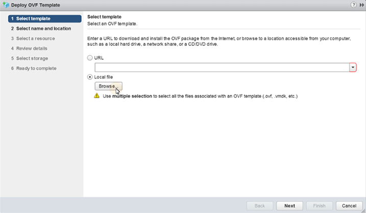
  2. Select an OVF template from a URL or a Local file.
    Figure 6. Deploy OVF Template
  3. Select a name and location of the virtual machine.
  4. Select a resource.
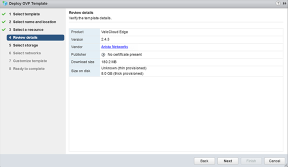
  5. Verify the template details.
    Figure 7. Review Details
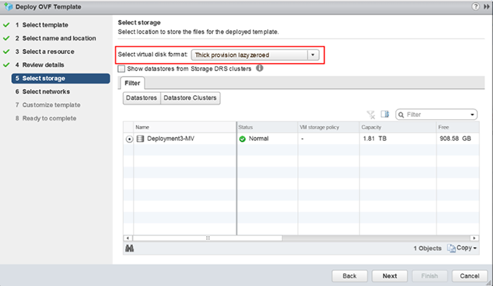
  6. Select the storage location to store the files for the deployment template.
    Figure 8. Select Storage
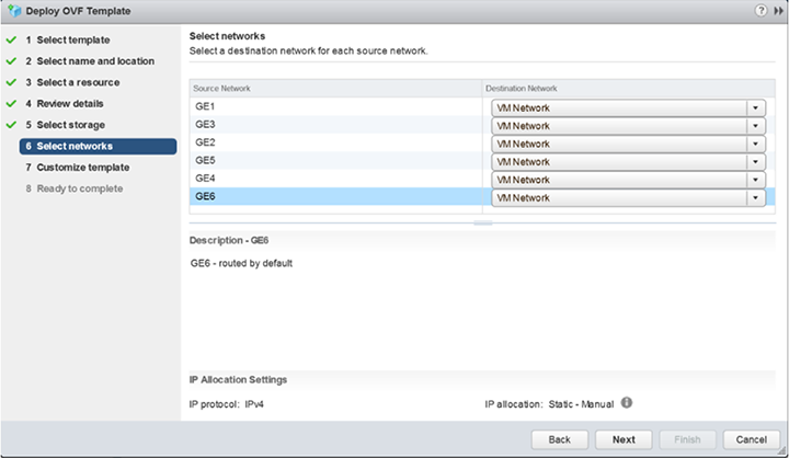
  7. Configure the networks for each of the interfaces.
    Note: Skip this step when using a cloud-init file to provision the Virtual Edge on ESXi.
    Figure 9. Select Networks
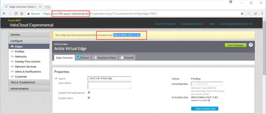
  8. Customize the template by specifying the deployment properties. The following image highlights:
    1. From the Orchestrator UI, retrieve the URL/IP Address. Use this address in Step c.
    2. Create a new Virtual Edge for the Enterprise. After the Edge is created, copy the Activation Key. Use this Activation Key in Step c.
      Figure 10. Activation Key
    3. On the Customize template page shown in the image below, enter the Activation Code and the Orchestrator URL/IP Address into the corresponding fields.
      Figure 11. Customize Template
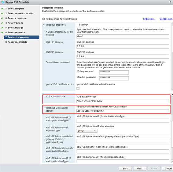
       

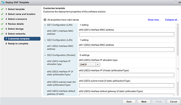
      Figure 12. Customize Template (contd..)
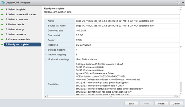
  9. Review the configuration data.
    Figure 13. Review Data
  10. Turn on the Virtual Edge.
    Figure 14. Power On Virtual Edge
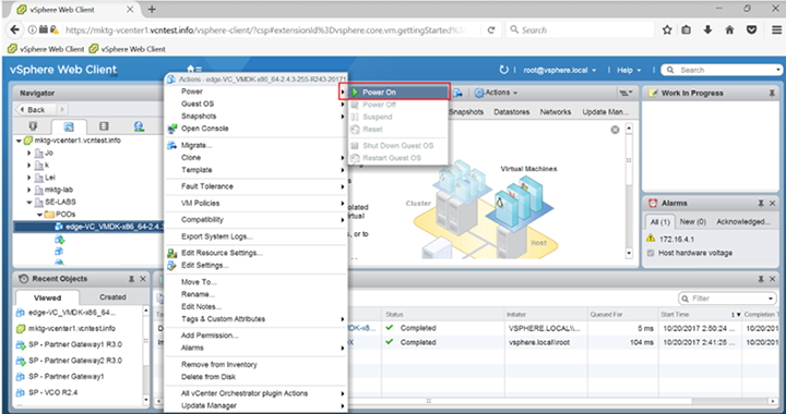
    After the Edge powers up, it establishes connectivity to the Orchestrator.