Install Partner Gateway
This document discusses the steps needed to install and deploy VeloCloud Gateway as a Partner Gateway. It also covers how to configure the VRF/VLAN and BGP configuration necessary on the Orchestrator on the Partner Gateway.
Installation Overview
This section provides an overview ofPartner Gateway installation.
About Partner Gateways
- One interface is facing the private and/or public WAN network and is dedicated to receiving VCMP encapsulated traffic from the remote edges, as well as standard IPsec traffic from Non SD-WAN Destinations.
- Another interface is facing the data center and provides access to resources or networks attached to a PE router, which the Partner Gateway is connected to. The PE router typically affords access to shared managed services that are extended to the branches, or access to a private (MPLS / IP-VPN) core network in which individual customers are separated.
The following distributions are provided:
| Provided | Description | Example |
|---|---|---|
| Arista | Gateway OVA package. | velocloud-vcg-X.X.X-GA.ova |
| KVM | Gateway qcow2 disk image. | velocloud-vcg-X.X.X-GA.qcow2 |
Minimum Hypervisor Hardware Requirements
The Gateway runs on a standard hypervisor (KVM or ESXi).
Minimum Server Requirements
- CPU: Intel XEON (10 cores minimum to run a single 8-core gateway VM) with minimum clock speed of 2.0 Ghz is required to achieve maximum performance.
- ESXi vmxnet3 network scheduling functions must have 2 cores reserved per Gateway virtual machine (VM), regardless of the number of cores assigned to the Gateway.
- Example: Assume there is a 24-core server running ESXi+vmxnet3. You can deploy 2- (8 core) Gateways. i.e. 2 gateways multiplied by 8 cores requires 16 cores reserved for gateway application and leaves 8 free cores. By using the formula above, in order to support these two Gateways running at peak performance scale the ESXi/vmxnet3 system requires an additional 4 cores (two cores for each of the two Gateways deployed). That is a total of 20 cores required to run 2 gateways on a 24 core system.
Note: When using SR-IOV, the network scheduling function is offloaded to the pNIC to achieve higher performance. However, the hypervisor must still perform other scheduling functions like CPU, memory, NUMA allocation management. It is required to always keep two free cores for hypervisor usage.
- Example: Assume there is a 24-core server running ESXi+vmxnet3. You can deploy 2- (8 core) Gateways. i.e. 2 gateways multiplied by 8 cores requires 16 cores reserved for gateway application and leaves 8 free cores. By using the formula above, in order to support these two Gateways running at peak performance scale the ESXi/vmxnet3 system requires an additional 4 cores (two cores for each of the two Gateways deployed). That is a total of 20 cores required to run 2 gateways on a 24 core system.
- ESXi vmxnet3 network scheduling functions must have 2 cores reserved per Gateway virtual machine (VM), regardless of the number of cores assigned to the Gateway.
- The CPU must support and activate the following instruction sets: AES-NI, SSSE3, SSE4, RDTSC, RDSEED, RDRAND, AVX/AVX2/AVX512.
- A minimum of 4GB free RAM must be available to the server system aside from the memory assigned to the PGW VMs. One Gateway VM requires 16GB RAM, or 32GB RAM if certificate-based authentication is activated.
- Minimum of 150GB magnetic or SSD based, persistent disk volume (One Gateway VM requires 64GB or 96GB Disk Volume, if certificate-based authentication is activated).
- Minimum required IOPS performance: 200 IOPS.
- Minimum 1x10Ge network interface ports and 2 ports is preferred when enabling the Gateway partner hand-off interface (1Ge NICs are supported, but will bottleneck performance). The physical NIC cards supporting SR-IOV are Intel 82599/82599ES and Intel X710/XL710 chipsets. (See the ‘Enable SR-IOV’ guide).
Note: SR-IOV does not support NIC bonding. For redundant uplinks, use ESXi vSwitch.
- VeloCloud Gateway is a data-plane intensive workload that requires dedicated CPU cycles to ensure optimal performance and reliability. Meeting these defined settings are required to ensure the Gateway VM is not oversubscribing the underlying hardware and causing actions that can destabilize the Gateway service (e.g. NUMA boundary crossing, memory, and/or vCPU over-subscription).
- Ensure that the SD-WAN Partner Gateway VM and the resources such as network interfaces, memory, physical CPUs used to support it fit within a single NUMA node.
-
Note: Configure the host BIOS settings as follows:
- Hyper-threading- Turned off
- Power Savings- Turned off
- CPU Turbo- Enabled
- AES-NI- Enabled
- NUMA Node Interleaving- Turned off
- Use ESXi host version: ESXi-6.7.0-14320388-standard or above
- Upgrade VM compatibility should be set before starting the GatewaySD-WAN Gateway instance
Example Server Specifications
| NIC Chipset | Hardware | Specification |
|---|---|---|
| Intel 82599/82599ES | HP DL380G9 | http://www.hp.com/hpinfo/newsroom/press_kits/2014/ComputeEra/HP_ProLiantDL380_DataSheet.pdf |
| Intel X710/XL710 | Dell PowerEdge R640 | https://www.dell.com/en-us/work/shop/povw/poweredge-r640
|
| Intel X710/XL710 | Supermicro SYS-6018U-TRTP+ | https://www.supermicro.com/en/products/system/1U/6018/SYS-6018U-TRTP_.cfm
|
| Intel E810-CQDA2 | Dell PowerEdge R640 | https://www.dell.com/en-us/work/shop/povw/poweredge-r640
|
Required NIC Specifications for SR-IOV Support
| Hardware Manufacturer | Firmware Version | Host Driver for Ubuntu 20.04.6 | Host Driver for Ubuntu 22.04.2 | Host Driver for ESXi 7.0U3 | Host Driver for ESXi 8.0U1a |
|---|---|---|---|---|---|
| Dual Port Intel Corporation Ethernet Controller XL710 for 40GbE QSFP+ | 7.10 | 2.20.12 | 2.20.12 | 1.11.2.5 and 1.11.3.5 | 1.11.2.5 and 1.11.3.5 |
| Dual Port Intel Corporation Ethernet Controller X710 for 10GbE SFP+ | 7.10 | 2.20.12 | 2.20.12 | 1.11.2.5 and 1.11.3.5 | 1.11.2.5 and 1.11.3.5 |
| Quad Port Intel Corporation Ethernet Controller X710 for 10GbE SFP+ | 7.10 | 2.20.12 | 2.20.12 | 1.11.2.5 and 1.11.3.5 | 1.11.2.5 and 1.11.3.5 |
| Dell rNDC X710/350 card | nvm 7.10 and FW 19.0.12 | 2.20.12 | 2.20.12 | 1.11.2.5 and 1.11.3.5 | 1.11.2.5 and 1.11.3.5 |
| Dual Port Intel Corporation Ethernet Controller E810-CQDA2 for 100GbE QSFP | 4.20 | ICE 1.11.14 | ICE 1.11.14 | Not supported yet | Not supported yet |
Supported Hypervisor Versions
| Hypervisor | Supported Versions |
|---|---|
| Arista |
|
| KVM |
|
Gateway Virtual Machine (VM) Specification
- If using Arista ESXi:
- Latency Sensitivity must be set to 'High'.
- Procedure (Adjust Latency Sensitivity)
- Browse to the virtual machine in the vSphere Client.
- To find a virtual machine, select a data center, folder, cluster, resource pool, or host.
- Select the VMs tab.
- Right-select the virtual machine, and then select Edit Settings.
- Select VM Options and select Advanced.
- Select a setting from the Latency Sensitivity drop-down menu.
- Select OK.
- Browse to the virtual machine in the vSphere Client.
- CPU reservation set to 100%.
- CPU shares set to high.
- CPU Limit must be set to Unlimited.
- 8 vCPUs (4vCPUs are supported but expect lower performance).
Important: All vCPU cores should be mapped to the same socket with the Cores per Socket parameter set to either 8 with 8 vCPUs, or 4 where 4 vCPUs are used.Note: Hyper-threading must be deactivated to achieve maximum performance.
- Procedure for Allocate CPU Resources:
- Select Virtual Machines in the Arista Host Client inventory.
- Right-click a virtual machine from the list and select Edit settings from the pop-up menu.
- On the Virtual Hardware tab, expand CPU, and allocate CPU capacity for the virtual machine.
Table 5. Virtual Machines Option Descriptions Option Description Reservation Guaranteed CPU allocation for this virtual machine. Limit Upper limit for this virtual machine’s CPU allocation. Select Unlimited to specify no upper limit. Shares CPU shares for this virtual machine in relation to the parent’s total. Sibling virtual machines share resources according to their relative share values bounded by the reservation and limit. Select Low, Normal, or High, which specify share values respectively in a 1:2:4 ratio. Select Custom to give each virtual machine a specific number of shares, which express a proportional weight.
- Procedure (Adjust Latency Sensitivity)
- CPU affinity must be activated. Follow the steps below:
- In the vSphere Web Client go to the VM Settings tab.
- Choose the Options tab and select .
- Add entries for
numa.nodeAffinity=0, 1, ..., where 0 and 1 are the processor socket numbers.
- vNIC must be of type 'vmxnet3' (or SR-IOV, see SR-IOV section for support details).
- Minimum of any one of the following vNICs:
- The First vNIC is the public (outside) interface, which must be an untagged interface.
- The Second vNIC is optional and acts as the private (inside) interface that can support VLAN tagging dot1q and Q-in-Q. This interface typically faces the PE router or L3 switch.
- Optional vNIC (if a separate management/OAM interface is required).
- Memory reservation is set to ‘maximum.’
- 16GB of memory (32GB RAM is required when enabling certificate-based authentication).
- 64 GB of virtual disk (96GB disk is required when enabling certificate- based authentication).
Note: Arista uses the above defined settings to obtain scale and performance numbers. Settings that do not align with the above requirements are not tested by Arista and can yield unpredictable performance and scale results.
- Latency Sensitivity must be set to 'High'.
- If using KVM:
- vNIC must be of 'Linux Bridge' type. (SR-IOV is required for high performance, see SR-IOV section for support details).
- 8 vCPUs (4vCPUs are supported but expect lower performance).
Important: All vCPU cores should be mapped to the same socket with the Cores per Socket parameter set to either 8 with 8 vCPUs, or 4 where 4 vCPUs are used.Note: Hyper-threading must be deactivated to achieve maximum performance.
- 16GB of memory (32GB RAM is required when enabling certificate- based authentication)
- Minimum of any one of the following vNICs:
- The First vNIC is the public (outside) interface, which must be an untagged interface.
- The Second vNIC is optional and acts as the private (inside) interface that can support VLAN tagging dot1q and Q-in-Q. This interface typically faces the PE router or L3 switch.
- Optional vNIC (if a separate management/OAM interface is required).
- 64 GB of virtual disk (96GB disk is required when enabling certificate- based authentication).
Firewall/NAT Requirements
- The firewall needs to allow outbound traffic from the Gateway to TCP/443 (for communication with Orchestrator).
- The firewall needs to allow inbound traffic from the Internet to UDP/2426 (VCMP), UDP/4500, and UDP/500. If NAT is not used, then the firewall needs to also allow IP/50 (ESP).
- If NAT is used, the above ports must be translated to an externally reachable IP address. Both the 1:1 NAT and port translations are supported.
Use of DPDK on Gateways
To improve packet throughput performance, Gateways take advantage of Data Plane Development Kit (DPDK) technology. DPDK is a set of data plane libraries and drivers provided by Intel for offloading TCP packet processing from the operating system kernel to processes running in user space and results in higher packet throughput. For additional details, see https://www.dpdk.org.
On Arista hosted Gateways and Partner Gateways, DPDK is used on interfaces that manage data plane traffic and is not used on interfaces reserved for management plane traffic. For example, on a typical Arista hosted Gateway, eth0 is used for management plane traffic and would not use DPDK. In contrast, eth1, eth2, and eth3 are used for data plane traffic and use DPDK.
Gateway Installation Procedures
In general, installing the Gateway involves the following steps:
Pre-Installation Considerations
The Partner Gateway provides different configuration options. A worksheet should be prepared before the installation of the Gateway.
| Gateway |
|
| Hypervisor | Address/Cluster name |
| Storage | Root volume data store (>40GB recommended) |
| CPU Allocation | CPU Allocation for KVM/Arista. |
| Installation Selections | DPDK—This is optional and enabled by default for higher throughput. If you choose to deactivate DPDK, contact Arista Customer Support |
| OAM Network |
|
| ETH0 – Internet Facing Network |
|
| Handoff (ETH1)- Network |
|
| Console access |
|
| NTP |
|
Gateway Section
Most of the Gateway section is self-explanatory.
| Gateway |
|
Creating a Gateway and Getting the Activation Key
- In the Operator portal, select the Gateway Management tab and go to Gateway Pools in the left navigation pane. The Gateway Pools page appears. Create a new Gateway pool. For running Gateway in the Service Provider network, check the Allow Partner Gateway check box. This will enable the option to include the partner gateway in this gateway pool.
Figure 1. Gateway Pool 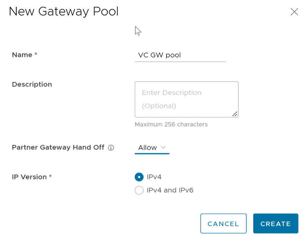
- In the Operator portal, select Gateway Management > Gateways and create a new gateway and assign it to the pool. The IP address of the gateway entered here must match the public IP address of the gateway. If unsure, you can run curl ipinfo.io/ip from the Gateway which will return the public IP of the Gateway.
Figure 2. New Gateway 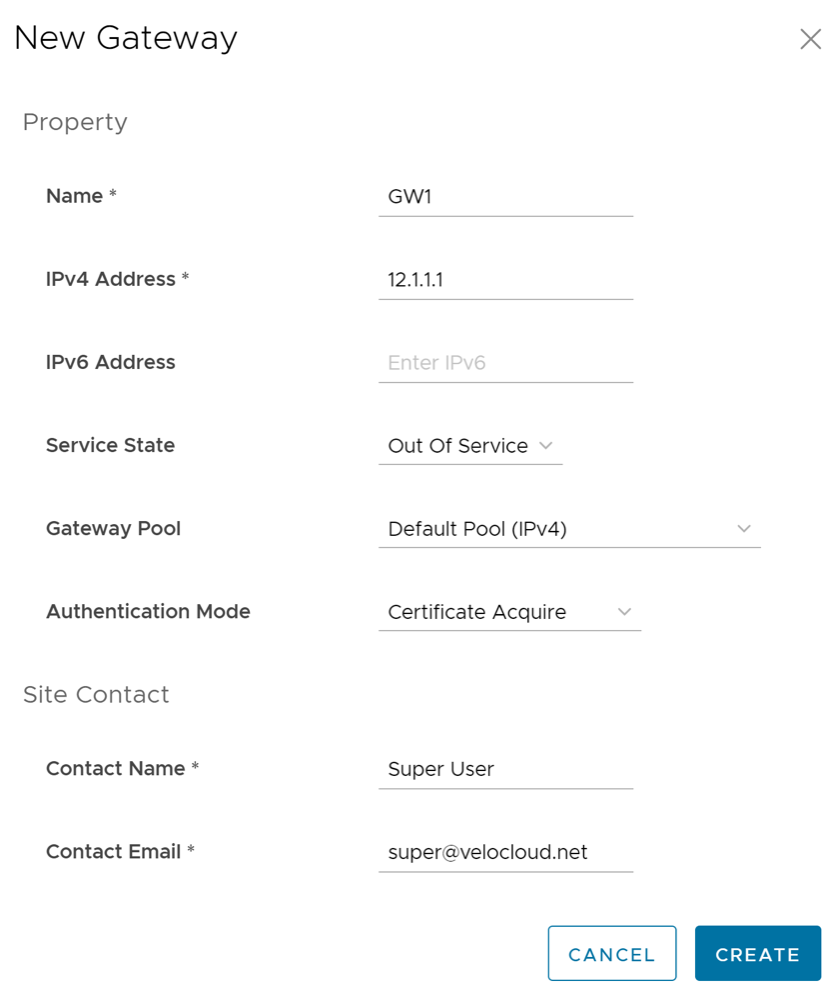
- Make a note of the activation key and add it to the worksheet.
Activate Partner Gateway Mode
- In the Operator portal, select Gateway Management > Gateways and select the Gateway. Check the Partner Gateway check box to activate the Partner Gateway.
Figure 3. Partner Gateway 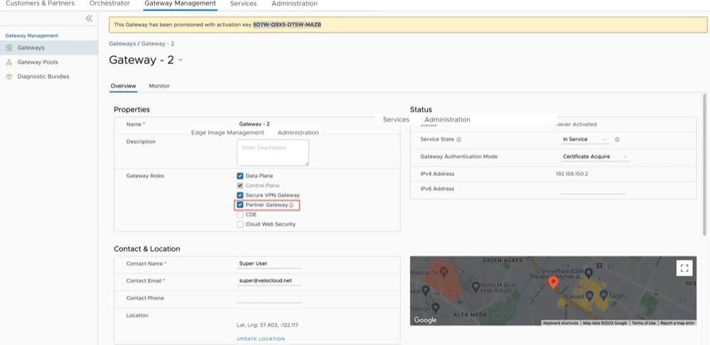
- There are additional parameters that can be configured. The most common are the following:
- Advertise
0.0.0.0/0with no encrypt – This option will enable the Partner Gateway to advertise a path to Cloud traffic for the SAAS Application. Since the Encrypt Flag is off, it will be up to the customer configuration on the business policy to use this path or not. - The second recommend option is to advertise the Orchestrator IP as a
/32with encrypt.This will force the traffic that is sent from the Edge to the Orchestrator to take the Gateway Path. This is recommended since it introduces predictability to the behavior that the Edge takes to reach the Orchestrator.
- Advertise
Networking
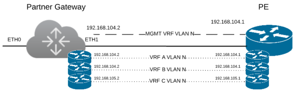
The diagram above is a representation of the Gateway in a 2-ARM deployment. In this example, we assume eth0 is the interface facing the public network (Internet) and eth1 is the interface facing the internal network (handoff or VRF interface).
For the Internet Facing network, you only need the basic network configuration.
| ETH0 – Internet Facing Network |
|
For the Handoff interface, you must know which type of handoff you want to configure and the Handoff configuration for the Management VRF.
| ETH1 – HANDOFF Network |
|
Console Access
| Console access |
|
In order to access the Gateway, a console password and/or an SSH public key must be created.
Cloud-Init Creation
The configuration options for the gateway that we defined in the worksheet are used in the cloud-init configuration. The cloud-init config is composed of two main configuration files, the meta data file and the user-data file. The meta-data contains the network configuration for the Gateway, and the user-data contains the Gateway Software configuration. This file provides information that identifies the instance of the Gateway being installed.
Below are the templates for both meta_data and user_data files. Network-config can be omitted and network interfaces will be configured via DHCP by default.
Fill the templates with the information in the worksheet. All #_VARIABLE_# must be replaced, and check any #ACTION#.
instance-id: #_Hostname_# local-hostname: #_Hostname_#version: 2 ethernets: eth0: addresses: - #_IPv4_Address_/mask# gateway4: #_IPv4_Gateway_# nameservers: addresses: - #_DNS_server_primary_# - #_DNS_server_secondary_# search: [] routes: - to: 0.0.0.0/0 via: #_IPv4_Gateway_# metric: 1 eth1: addresses: - #_MGMT_IPv4_Address_/Mask# gateway4: 192.168.152.1 nameservers: addresses: - #_DNS_server_primary_# - #_DNS_server_secondary_# search: [] routes: - to: 0.0.0.0/0 via: #_MGMT_IPv4_Gateway_# metric: 13#cloud-config hostname: #_Hostname_# password: #_Console_Password_# chpasswd: {expire: False} ssh_pwauth: True ssh_authorized_keys: - #_SSH_public_Key_# velocloud: vcg: vco: #_VCO_# activation_code: #_Activation_Key# vco_ignore_cert_errors: falseThe default username for the password that is configured in the user-data file is 'vcadmin'. Use this default username to login to the Gateway for the first time.
sed s/[”“]/'"'/g /tmp/user-data > /tmp/user-data_newCreate ISO File
Once you have completed your files, they need to be packaged into an ISO image. This ISO image is used as a virtual configuration CD with the virtual machine. This ISO image, called vcg01-cidata.iso, is created with the following command on a Linux system:
genisoimage -output vcg01-cidata.iso -volid cidata -joliet -rock user-data meta-data network-configIf you are on a MAC OSX, use the command below instead:
mkisofs -output vcg01-cidata.iso -volid cidata -joliet -rock {user-data,meta-data,network-config}This ISO file which we will call select is going to be used in both OVA and Arista installations.
Install Gateway
You can install Gateway on Arista and KVM.
- SR-IOV
- Linux Bridge
- OpenVSwitch Bridge
- On KVM, see Install Gateway on KVM
- On Arista, see Install Gateway on Arista
Enable SR-IOV on Arista
Enabling SR-IOV on Arista is an optional configuration.
Prerequisites
- Intel 82599/82599ES
- Intel X710/XL710
To enable SR-IOV on Arista, perform the following steps:
- Make sure that your NIC card supports SR-IOV. Check the Arista Hardware Compatibility List (HCL)
Brand Name: Intel
I/O Device Type: Network
Features: SR-IOV
Figure 5. Arista Compatibility 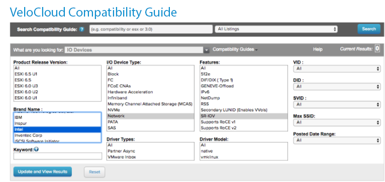 Refer Arista KB article on details of how to enable SR-IOV on the supported NIC.
 - Once you have a support NIC card, go to the specific Arista host, select the Configure tab, and then choose Physical adapters
Figure 6. Physical Adapters 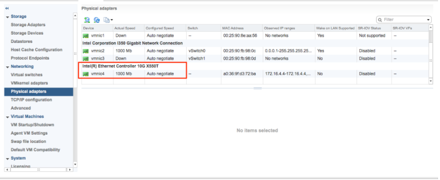
- Reboot the hypervisor.
Figure 7. Edit Settings 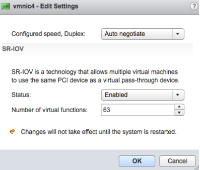
- If SR-IOV is successfully enabled, the number of Virtual Functions (VFs) will show under the particular NIC after ESXi reboots.
Figure 8. Adapters 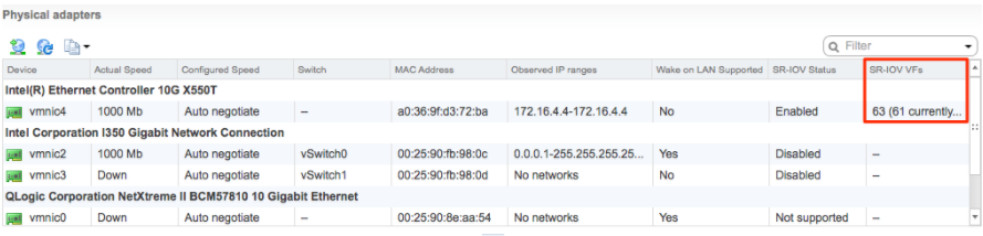 Note: To support VLAN tagging on SR-IOV interfaces, user must configure VLAN ID 4095 (Allow All) on the Port Group connected to the SR-IOV interface. For additional information, see VLAN Configuration.
Install Gateway on Arista
If you decide to use SR-IOV mode, then you can optionally enable SR-IOV on Arista. To enable the SR-IOV on Arista, see Enable SR-IOV on Arista.
To install the Gateway OVA on Arista, perform the following steps:
- Select the ESXi host, go to Actions, and then Deploy OVF Template. Select the Gateway OVA file provided by Arista and select Next.
Figure 9. Select Templates 
Review the template details in Step 4 ( Review details) of the Deploy OVA/OVF Template wizard as shown in the image below.
Figure 10. Review Details 
- For the Select networks step, the OVA comes with two pre-defined networks (vNICs).
Table 11. Select Networks vNIC Descriptions vNIC Description Inside This is the vNIC facing the PE router and is used for handoff traffic to the MPLS PE or L3 switch. This vNIC is normally bound to a port group that does a VLAN pass-through (VLAN=4095 in vswitch configuration). Outside This is the vNIC facing the Internet. This vNIC expects a non-tagged L2 frame and is normally bound to a different port group from the Inside vNIC. Figure 11. Select Networks 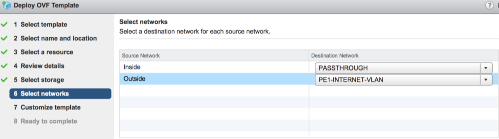
- For the Customize template step, do not change anything. This is when you use vApp to configure the VM. We will not use vApp in this example. Click Next to continue with deploying the OVA.
Figure 12. Customize Template 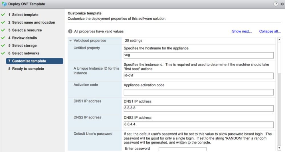
- Once the VM is successfully deployed, return to the VM and select Edit Settings. Two vNICs are created with adapter type = vmxnet3.
Figure 13. Edit settings 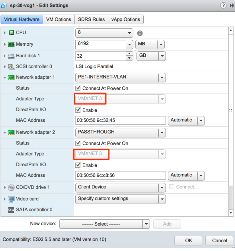
- (Optional for SR-IOV) This step is required only if you plan to use SR-IOV. Because the OVA by default creates the two vNICs as vmxnet3, we will need to remove the two vNICs and re-add them as SR-IOV.
Figure 14. Re-add vNICs 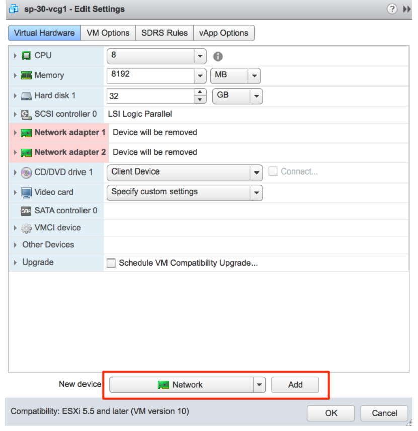
When adding the two new SR-IOV vNICs, use the same port group as the original two vmxnet3 vNICs. Make sure the Adapter Type is SR-IOV passthrough. Select the correct physical port to use and set the Guest OS MTU Change to Allow. After you add the two vNICs, select OK.
Figure 15. SR-IOV Passthrough 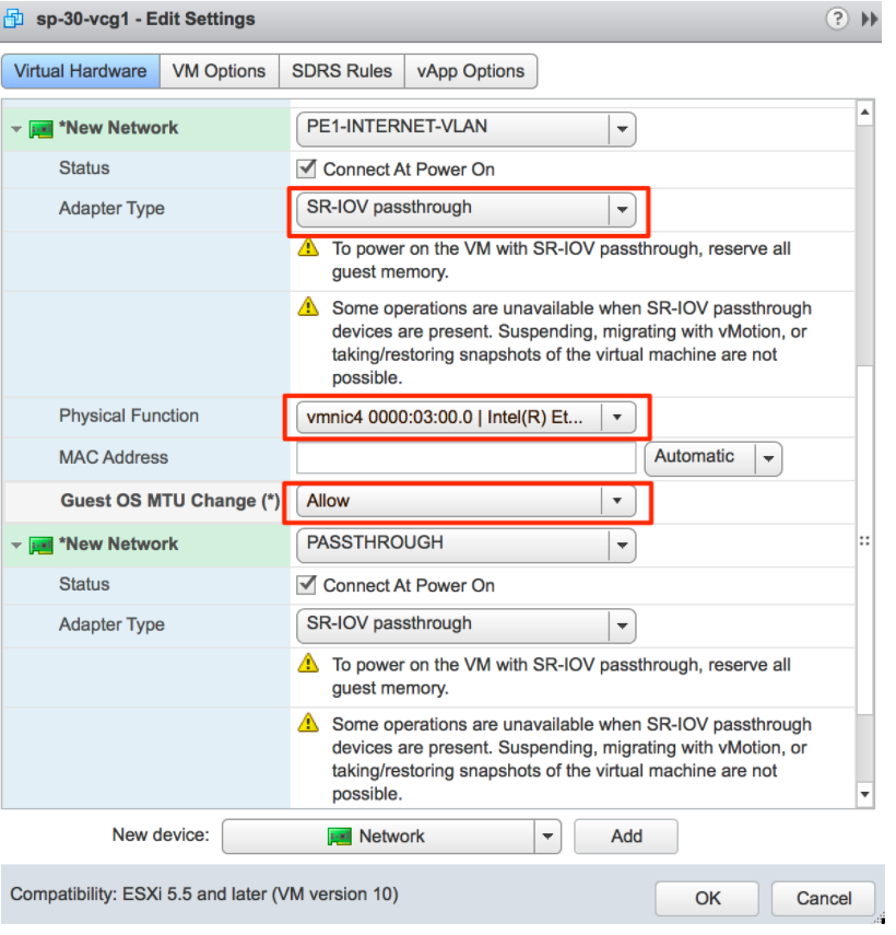

- Refer to Cloud-init Creation. The Cloud-init file is packaged as a CD-ROM (iso) file. You need to mount this file as a CD-ROM.
Note: You must upload this file to the data store.
Figure 17. CD-ROM File Mount 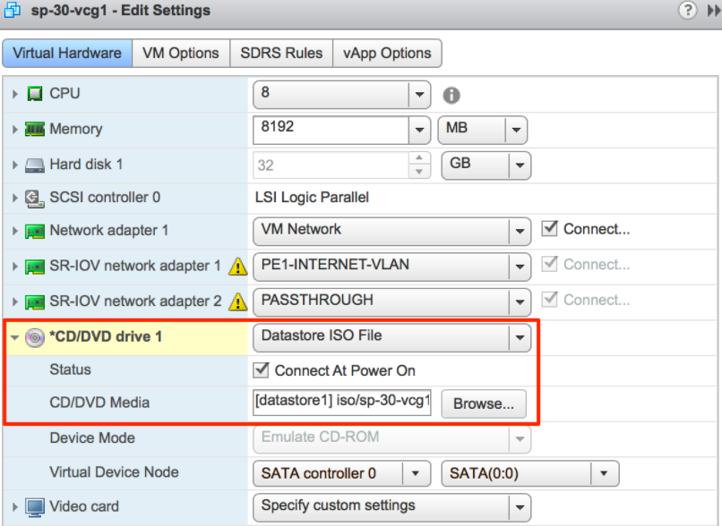
Activate SR-IOV on KVM
- Intel 82599/82599ES
- Intel X710/XL710
- Before using the Intel X710/XL710 cards in SR-IOV mode on KVM, make sure the supported Firmware and Driver versions specified in the Deployment Prerequisites section are installed correctly.
- SR-IOV mode is not supported if the KVM Virtual Edge is deployed with a High-Availability topology. For High-Availability deployments, ensure that SR-IOV is not enabled for that KVM Edge pair.
To enable SR-IOV on KVM, perform the following steps:
Validating SR-IOV (Optional)
lspci | grep -i EthernetVerify if you have Virtual Functions:
01:10.0 Ethernet controller: Intel Corporation 82599 Ethernet Controller Virtual Function(rev 01)Install Gateway on KVM
Discusses how to install the Gateway qcow on KVM.
Pre-Installation Considerations
KVM provides multiple ways to provide networking to virtual machines. The networking in libvirt should be provisioned before the VM configuration. There are multiple ways to configure networking in KVM. For a full configuration of options on how to configure Networks on libvirt, see the following link:
https://libvirt.org/formatnetwork.html.
- SR-IOV (This mode is required for the Gateway to deliver the maximum throughput specified by Arista)
- OpenVSwitch Bridge
If you decide to use SR-IOV mode, enable SR-IOV on KVM. To enable the SR-IOV on KVM, see Activate SR-IOV on KVM.
Gateway Installation Steps on KVM- Create the Network interfaces that you are going to use for the device.
Using SR-IOV: The following is a sample network interface template specific to Intel X710/XL710 NIC cards using SR-IOV.
<interface type='hostdev' managed='yes'> <mac address='52:54:00:79:19:3d'/> <driver name='vfio'/> <source> <address type='pci' domain='0x0000' bus='0x83' slot='0x0a' function='0x0'/> </source> <model type='virtio'/> </interface>Using OpenVSwitch: The following are the sample templates of a network interface using OpenVSwitch.git ./vcg/templates/KVM_NETWORKING_SAMPLES/template_outside_openvswitch.xml<?xml version="1.0" encoding="UTF-8"?> <network> <name>public_interface</name> <!--This is the network name--> <model type="virtio" /> <forward mode="bridge" /> <bridge name="publicinterface" /> <virtualport type="openvswitch" /> <vlan trunk="yes"> <tag id="50" /> <!--Define all the VLANS for this Bridge --> <tag id="51" /> <!--Define all the VLANS for this Bridge --> </vlan> </network>Create a network for inside_interface:
git ./vcg/templates/KVM_NETWORKING_SAMPLES/template_inside_openvswitch.xml
If you are using OpenVSwitch mode, then you have to verify if the basic networks are created and active before launching the VM.<network> <name>inside_interface</name> <!--This is the network name--> <model type='virtio'/> <forward mode="bridge"/> <bridge name="insideinterface"/> <virtualport type='openvswitch'></virtualport> <vlan trunk='yes'></vlan> <tag id='200'/> <!—Define all the VLANS for this Bridge --> <tag id='201'/> <!—Define all the VLANS for this Bridge --> <tag id='202'/> <!—Define all the VLANS for this Bridge --> </network>Note: This validation step is not applicable for SR-IOV mode as you do not create any network before the VM is launched.Figure 18. Validation Step 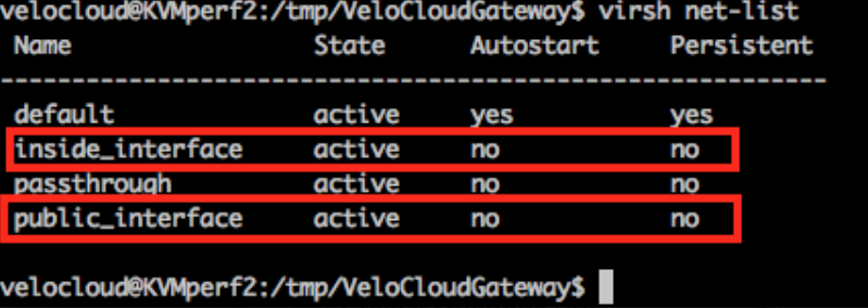
- Launch the VM by performing the following steps:
- Ensure you have the following three files in your directory as shown in the following sample screenshot:
- qcow file-
vcg-root - cloud-init-
vcg-test.iso - Domain XML file that defines the VM-
test_vcg.xml, wheretest_vcgis the domain name.)
Figure 19. Directory Files 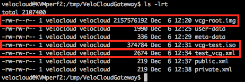
- qcow file-
- Define VM.
velocloud@KVMperf2:/tmp/VeloCloudGateway$ virsh define test_vcg.xml Domain test_vcg defined from test_vcg.xml - Set VM to autostart.
velocloud@KVMperf2:/tmp/VeloCloudGateway$ virsh autostart test_vcg - Start VM.
velocloud@KVMperf2:/tmp/VeloCloudGateway$ virsh start test_vcg
- Ensure you have the following three files in your directory as shown in the following sample screenshot:
Post-Installation Tasks
If everything worked as expected in the installation, you can now login to the VM.
- If everything works as expected, you should see the login prompt on the console. You should see the prompt name as specified in cloud-init.
Figure 20. Login Prompt 
- You can also refer to
/run/cloud-init/result.json. If you see the message below, it is likely that the cloud init runs successfully.Figure 21. cloud init Successful Message 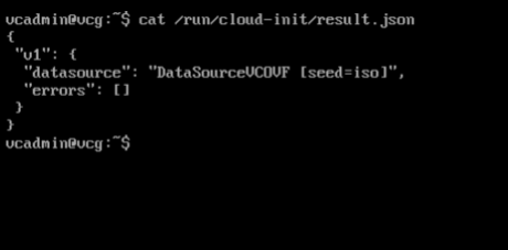
- Verify that the Gateway is registered with Orchestrator.
Figure 22. Verify Registered Gateway 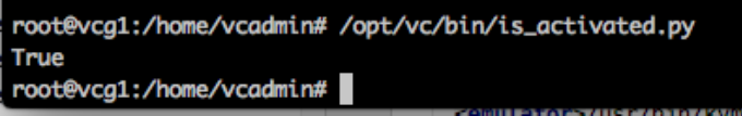
- Verify Outside Connectivity.
Figure 23. Verify Outside Connectivity 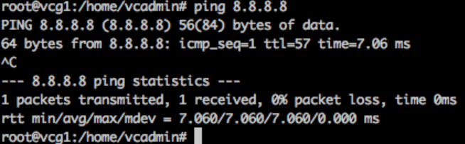
- Verify that the MGMT VRF is responding to ARPs.
Figure 24. Verify MGMT VRF 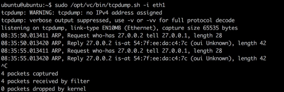
- Associate the new gateway pool with the customer.
Figure 25. Associate Gateway Pool 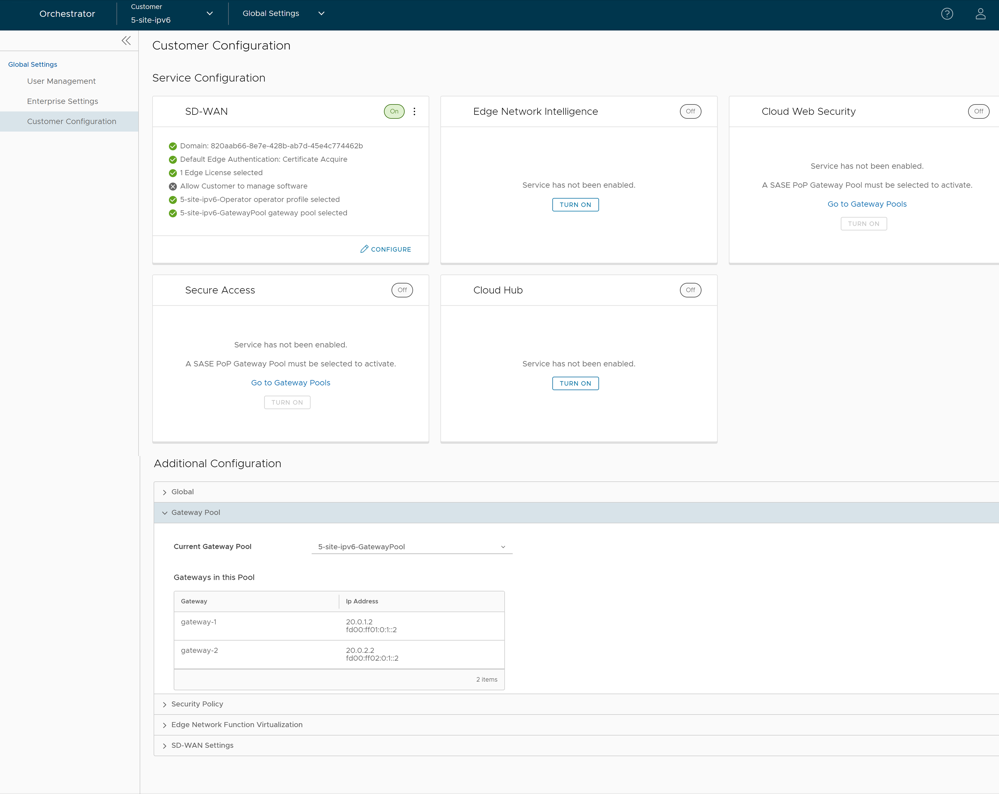
- Verify that the Edge is able to establish a tunnel with the Gateway on the Internet side. From the Orchestrator, go to
From the Orchestrator, go to , and select Run to view the list of active paths.
Figure 26. List of Active Paths 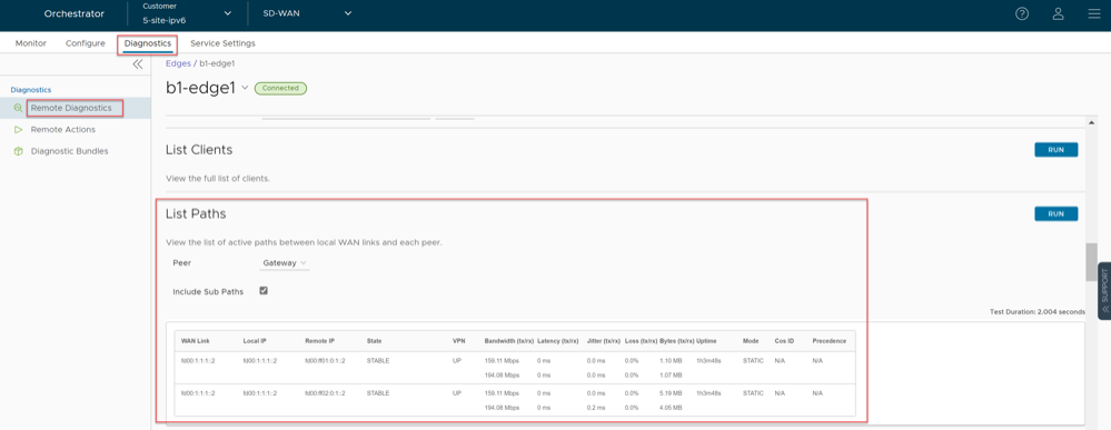
Configure Handoff Interface in Data Plane
In the example featuring figure below (VRF/VLAN Hand Off to PE), we assume eth0 is the interface facing the public network (Internet) and eth1 is the interface facing the internal network (customer VRF through the PE).BGP peering configuration is managed on the VCO on a per customer/VRF basis under . Note that the IP address of each VRF is configurable per customer. The IP address of the management VRF inherits the IP address configured on the SD-WAN Gateway interface in Linux.
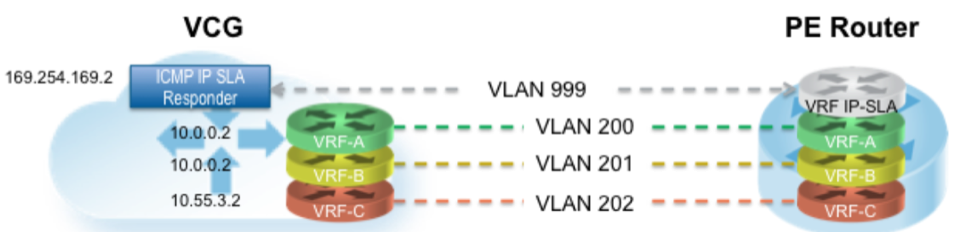
A management VRF is created on the SD-WAN Gateway and is used to send periodic ARP refresh to the default Gateway IP to determine the next-hop MAC. It is recommended that a dedicated VRF is set up on the PE router for this purpose. The same management VRF can also be used by the PE router to send IP SLA probe to the SD-WAN Gateway to check for SD-WAN Gateway status (SD-WAN Gateway has stateful ICMP responder that will respond to ping only when its service is up). BGP Peering is not required on the Management VRF. If a Management VRF is not set up, then you can use one of the customer VRFs as Management VRF, although this is not recommended.
Remove Blocked Subnets
By default, the SD-WAN Gateway blocks traffic to 10.0.0.0/8 and 172.16.0.0/14. We will need to remove them before using this SD-WAN Gateway because we expect SD-WAN Gateway to be sending traffic to private subnets as well. If you do not edit this file, when you try to send traffic to blocked subnets, you will find the following messages in
/var/log/gwd.log
2015-12-18T12:49:55.639 ERR [NET] proto_ip_recv_handler:494 Dropping packet destined for 10.10.150.254, which is a blocked subnet. 2015-12-18T12:52:27.764 ERR [NET] proto_ip_recv_handler:494 Dropping packet destined for 10.10.150.254, which is a blocked subnet. [message repeated 48 times] 2015-12-18T12:52:27.764 ERR [NET] proto_ip_recv_handler:494 Dropping packet destined for 10.10.150.10, which is a blocked subnet.- On SD-WAN Gateway,
edit
/opt/vc/etc/vc_blocked_subnets.jsonfile
. You will find that this file first has the following.[ { "network_addr": "10.0.0.0", "subnet_mask": "255.0.0.0" }, { "network_addr": "172.16.0.0", "subnet_mask": "255.255.0.0" } ] - Remove the two networks. The file should look like below after editing. Save the change.
[ ] - Restart the SD-WAN Gateway process by
sudo /opt/vc/bin/vc_procmon
restart
.
Upgrade Gateway
This section discusses how to upgrade a Gateway installation.
Authenticate Software Update Package Via Digital Signature
The software installer in the Orchestrator version 4.3.0 and higher now has the ability to authenticate the software update package using a digital signature.
Prior to upgrading to a newer version of the software, make sure the public key exists to verify the package. The known public key location to verify signature is as follows, /var/lib/velocloud/software_update/keys/software.key. Alternatively, the key can be provided on the command line using --pubkey parameter.
The current release public key is:
-----BEGIN PUBLIC KEY----- MHYwEAYHKoZIzj0CAQYFK4EEACIDYgAEbjZ08w3RNJvuOICBp8fysU/3opLejsrP pArA1IyKeUzU0U31MU4kPcLdggojobNfs3i1kvyvGvprEmfGYWzc3dXUyT9Tv73C lVgYPLNd/nOxJsXomROKogfvJdYFuy4/ -----END PUBLIC KEY----If the key is missing or the signature cannot be verified, the Operator will be notified that the package is untrusted with an option to proceed or not proceed.
To skip verification, use "--untrusted" parameter.
If running in batch mode or not on the terminal, the installation is aborted unless the "--untrusted" option is specified on the command line.
By default, the installer will run in interactive mode and may issue prompts. For automated scripts, use --batch parameter to suppress prompts.
Upgrade Procedures
- Download the Gateway update package.
- Upload the image to the Gateway system (using, for example, the scp command). Copy the image to the following location on the system:
/var/lib/velocloud/software_update/vcg_update.tar - Connect to the Gateway console and run:
sudo /opt/vc/bin/vcg_software_update
Activate Replacement Partner Gateway
This section discusses activating a replacement Partner Gateway.
Overview
Gateway activation keys do not have the same default 30 day lifetime as Edges. In fact, a Gateway activation key has an infinite lifespan. If an on-premises Gateway fails and you wish to replace it with a newly built Gateway using the same name and IP address, you can use the same activation key that was used on the original Gateway.
As a result, for most Gateway issues, the quickest method of recovery is to spin up a new VM and register it to the Orchestrator using the failed Gateway’s activation key. This saves you a lot of time as the Orchestrator will push the existing configuration onto this new instance. Most Partners prefer this approach over configuring a new Gateway from scratch.
Prerequisites
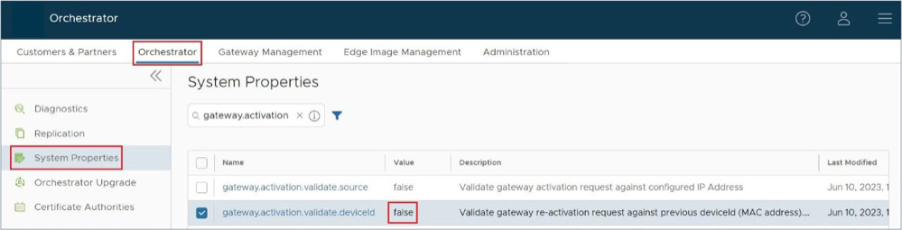
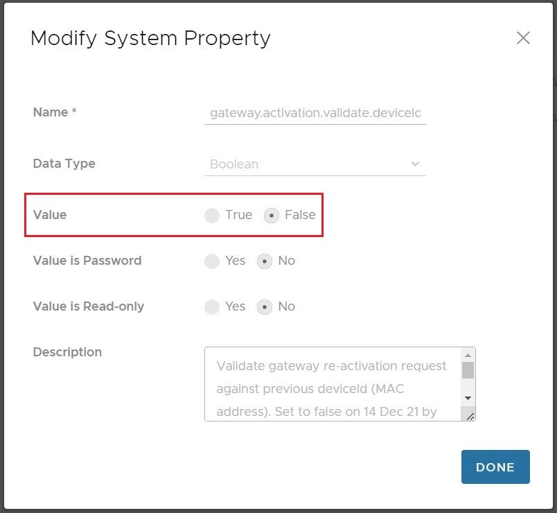
Before you can use this Gateway replacement method, you must adjust the System Property gateway.activation.validate.deviceID and set the value to false. To do this you or another Operator with a Superuser role must go to and search for gateway.activation and inspect gateway.activation.validate.deviceID. If the Value is already false as in the screenshot below, then you are ready for the next steps. If the Value is true, then a Gateway reactivation will not work, and you need to modify this System Property by selecting it.
Replacement Partner Gateway Workflow
- Locate the original activation key. This key is found by going to and selecting the name of the Gateway you are replacing. Click the down arrow beside the name and note the activation key.
Figure 30. Gateway Management 
- Use the activation key to activate the replacement Gateway on your newly spun up VM:
/opt/vc/bin/activate.py -s vco_name_or_ip
activation_key
.
Custom Configurations
This section discusses custom configurations.
NTP Configuration
NTP configuration involves editing the /etc/ntpd.conf file.
OAM Interface and Static Routes
- Add an additional interface to the VM (ETH2).
Arista: If a dedicated VNIC for Management/OAM is desired, add another vNIC of type vmxnet3. You must repeat the previous step, which is to select OK and then Edit Settings again so you can make a note of the vNIC MAC address.
Figure 31. vNIC MAC Address 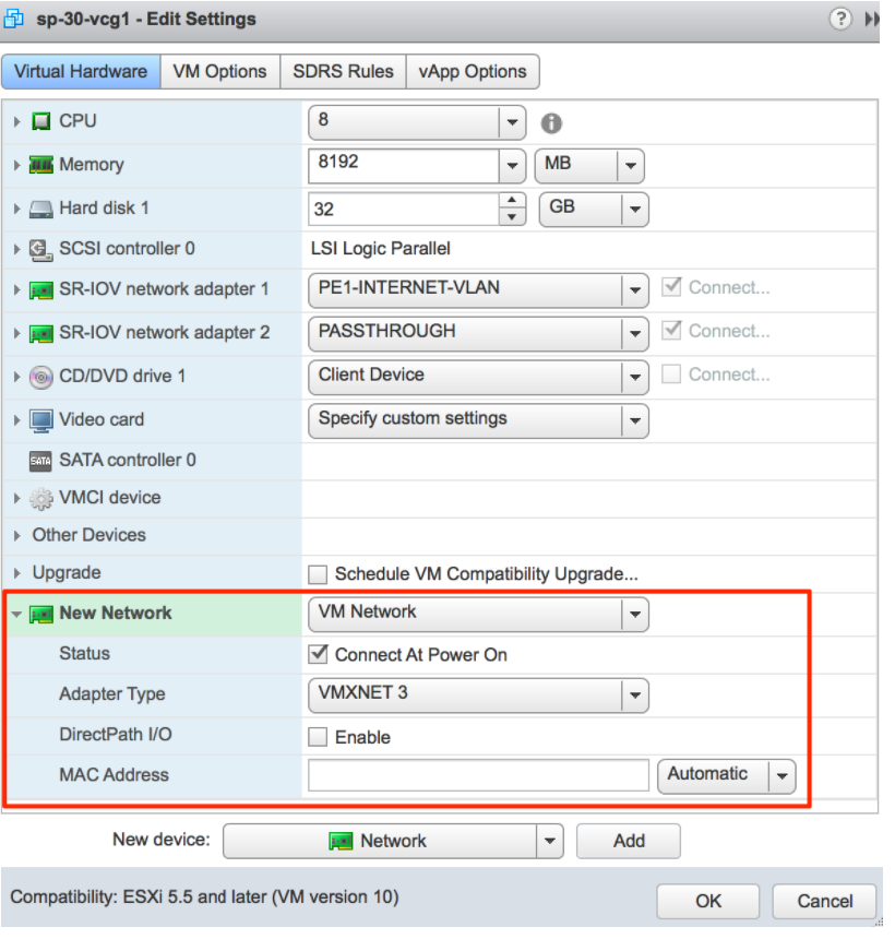
KVM: If a dedicated VNIC for Management/OAM is desired, make sure you have a libvirt network named oam-network. Then add the following lines to your XML VM structure:
….. </controller> <interface type='network'> <source network='public_interface'/> <vlan><tag id='#public_vlan#'/></vlan> <alias name='hostdev1'/> <address type='pci' domain='0x0000' bus='0x00' slot='0x11' function='0x0'/> </interface> <interface type='network'> <source network='inside_interface'/> <alias name='hostdev2'/> <address type='pci' domain='0x0000' bus='0x00' slot='0x12' function='0x0'/> </interface> <interface type='network'> <source network='oam_interface'/> <vlan><tag id='#oam_vlan#'/></vlan> <alias name='hostdev2'/> <address type='pci' domain='0x0000' bus='0x00' slot='0x13' function='0x0'/> </interface> <serial type='pty'> <source path='/dev/pts/3'/> <target port='0'/> <alias name='serial0'/> </serial>
OAM - SR-IOV with vmxnet3 or SR-IOV with VIRTIO
It is possible in some installations to mix and match and provide different interface types for the Gateway. This generally happens if you have an OAM without SR-IOV. This custom configuration requires additional steps since this causes the interfaces to come up out of order.
Record the MAC address of each interface.
Arista: After creating the machine, go to Edit Settings and copy the Mac address.
KVM: After defining the VM, run the following command:

Special Consideration When Using 802.1ad Encapsulation
It seems certain that 802.1ad devices do not populate the outer tag EtherType with 0x88A8. Special change is required in user data to interoperate with these devices.
Assuming a Management VRF is configured with S-Tag: 20 and C-Tag: 100, edit the vrf_vlan section in / etc/ config/ gatewayd as follows. Also, define resp_mode to 1 so that the Gateway will relax its check to allow Ethernet frames that have incorrect EtherType of 0x8100 in the outer header.
SNMP Integration
For additional information on SNMP configuration, see Net-SNMP documentation. To configure SNMP integration:
Custom Firewall Rules
This section discusses how to modify custom firewall rules.
To modify local firewall rules, edit the following file: /etc/iptables/rules.v4.
*filter :INPUT ACCEPT [0:0] -A INPUT -p udp -m udp --source 127.0.0.1 --dport 161 -m comment --comment "allow SNMP port" -j ACCEPT :FORWARD ACCEPT [0:0] :OUTPUT ACCEPT [0:0] COMMITRestart netfilter service:
service netfilter-persistent restart service vc_process_monitor restart