Cabling the Switch
Grounding the Switch
After mounting the switch into the rack, connect the switch to the data center ground.
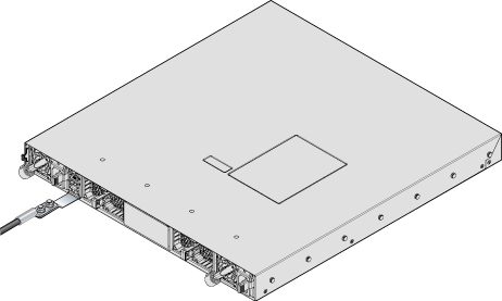
Figure 1 displays the location of the grounding pads located on the bottom corners of the rear panel for the models that have no management ports on the rear panel. Figure 2 displays the location of the grounding pads on the rear panel for models that have management ports on the rear panel. There are threaded holes under the sticker on the right (next to PS2) that warns about “1 min”.Figure 3 displays the location of the grounding assembly on the rear panel for DCS-7280CR3-32P4.
À la terre et de mise à la terre fils cosses (M4 x 0.7) ne sont pas fournis. Calibre des fils doit satisfaire des exigences de l’installation locale et nationale. Disponible dans le commerce 6 fils AWG est recommandé pour les installations aux États-Unis.
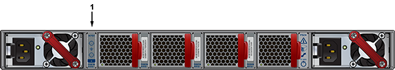
| 1 | Earth grounding pads |
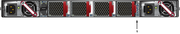
| 1 | Earth grounding pads |
Grounding Adapter Assembly (KIT-GND-EXT-1RU)
The following steps assemble and attach a grounding assembly to the chassis before mounting it into the rack.
| Switch | Grounding Kit Adapter |
|---|---|
| 7280PR3-24 | KIT-GND-EXT-1RU |
| 7280PR3K-24 | KIT-GND-EXT-1RU |
| 7280DR3-24 | KIT-GND-EXT-1RU |
| 7280DR3K-24 | KIT-GND-EXT-1RU |
| 7280CR3-32P4 | KIT-GND-EXT-1RU |
| 7280CR3K-32P4 | KIT-GND-EXT-1RU |
| 7280CR3MK-32P4 | KIT-GND-EXT-1RU |
| 7280DR3-32P4 | KIT-GND-EXT-1RU |
| 7280DR3K-32P4 | KIT-GND-EXT-1RU |
Figure 4 shows the exploded and assembled views.
- Identify all the components to be assembled:
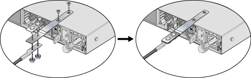
Note: The chassis is shown upside down in the figure above.- 1x Grounding adapter
- 1x Grounding bracket
- 2x Flat-head screws (Phillips,M4 x 5.00 long, stainless steel)
- 2x Hex nuts (#10-32, Serrated Flange, stainless steel)
- 1x Grounding lug (Copper, 2-hole, 6 AWG, straight barrel)
- 1x Grounding bracket
- 1x Grounding adapter
- Insert the grounding adapter through the holes in the grounding bracket.
- Insert the ground lug on to the grounding adapter studs and fasten using the hex nuts to form the grounding assembly.
- With the chassis on its top on a flat surface, attach the grounding assembly to the chassis using the flat head screws.
- Turn the chassis over before mounting it into a rack and connecting cables.
Connecting Power Cables
Power cords are optional and must be ordered separately. You must use an approved power cord compliant with local and national electrical codes or order one from Arista for use with the device.
Installation de cet équipement doit être conformes aux codes électriques locaux et nationaux. Si nécessaire, consulter les organismes de réglementation appropriés et des autorités de contrôle pour assurer la conformité.
The switch operates with two installed power supplies. At least one power supply must connect to a power source. Two circuits provide redundancy protection. Rear Panel displays the location of the power supplies on the rear panel of the switch.
- Non-Redundant Configuration: Connect power to either of the two power supplies.
- Redundant Power Supply Configuration: Connect power to both power supplies.
- Power down the Switch: Remove all power cords and wires from the power supplies.
Important: This equipment must be grounded. Never defeat the ground conductor.
Cet équipement doit être mis à la terre. Ne jamais modifier le conducteur de terre.
Important: This unit requires overcurrent protection.Cet appareil requiert une protection contre les surintensités.
AC Power Supplies
The following AC power supplies are supported.
| PWR-500AC | PWR-745AC | PWR-1011-AC |
| PWR-511-AC | PWR-747AC | PWR-1511-AC |
Figure 5 displays an AC power supply, including the power socket on the left side of the module. The AC power supply connects to a circuit that provides the required power, as specified by Table 4.
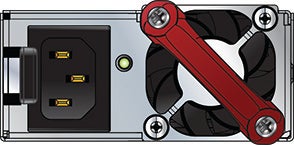
The power supplies require power cables that comply with IEC-320 and have a C14 connector. The accessory kit provides two IEC-320 C13 to C14 power cables.
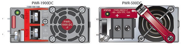
DC Power Supplies
The following DC power supplies are supported.
| PWR-500-DC | PWR-1900-DC | PWR-1511-DC |
| PWR-511-DC | PWR-1011-DC |
The following image displays examples of DC power supplies.
Un dispositif de sectionnement doit être fourni dans le cadre de l'installation.
Pouvoir assurer qu'il est retiré de circuits DC avant d'effectuer des actions d'installation . Localiser les disjoncteurs ou des fusibles sur les lignes de courant continu desservant les circuits. Coupez les circuits de lignes d'alimentation ou retirer les fusibles.
Le calibre du fil doit être conforme aux exigences locales et nationales et les codes électriques. Utiliser du fil de cuivre.
Appliquer connexion à la terre à l'interrupteur premier lors de l'installation et de supprimer la dernière alimentation lors du débranchement.
Wire and Lug Preparation
Before performing any installation actions, ensure power is removed from DC circuits by turning off the power line servicing the circuits. Prepare the stranded wiring before you begin a DC power installation.
- Attach an ESD grounding strap.
- Prepare the stranded copper wiring for the power supply to be used. Table 4 provides wiring, lug, and tightening torque information for the power supplies covered in this guide.
Table 2. Wiring, Lug, and Tightening Torques for DC PSUs PSU Wire Size(1) Lug Type(2) Tightening Torque (AWG) (mm2) N•m in.•lbs. PWR-500-DC 14 or larger 2.0 or larger ring or spade/fork 1.0 9 PWR-511-DC 12 - 14 4.0 - 2.5 1.0 9 PWR-1900-DC 4 - 6 21.2 - 13.3 2.7 24 PWR-1011-DC 6 - 8 16.0 - 10.0 2.7 24 PWR-1511-DC 4 - 6 25.0 - 16.0 2.7 24
- Unless otherwise noted, wire size applies to -48V, Battery return, and Protective earth wires.
- Unless otherwise noted, twin #10 studs spaced for dual-hole lug with 5/8" hole spacing.
- Strip the wires to the appropriate length for the lugs to be used.
- Use agency-approved compression (pressure) lugs for wiring terminations.
- Slip on heat-shrink tubing on the wire ends before assembling the lugs on to the wire.
- Crimp the lugs with the proper tool, and ensure that the tubing extends over the barrel of the lugs and the insulation on the wires (Lug Preparation).
- Shrink the tubing with a heat gun.
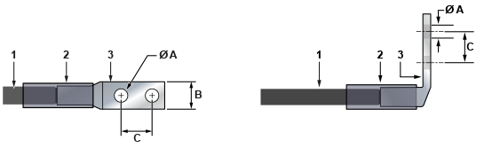
| 1 | Insulated wire | 3 | Lug | B | 1/2” |
| 2 | Heat-shrink tubing | A | 1/4” | C | 5/8” |
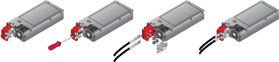
Connecting a DC Power Supply to Power Source
Figure 8 displays an example of connecting a PSU. To connect a DC power supply to a power source, perform the following:
- Prepare the stranded wiring (Wire and Lug Preparation).
- Attach the appropriate lugs to the source DC wires.
- Connect the DC-input wires to the appropriate terminals using the specified torque (Table 4) in the following order.
Note: Remove terminal covers as needed.
- Ground wire to the Protective Earth (PE
 ) terminal.
 - Negative source DC cable to the negative (- / -48V) terminal.
- Positive (+) source DC cable to the positive (+ / Rtn) terminal.
- Ground wire to the Protective Earth (PE
- Replace the terminal covers as required.
Figure 8. DC PSU Connection Example
Connecting Serial and Management Cables
- RJ-45 to DB-9 serial adapter cable.
- RJ-45 Ethernet cable.
Table 3 lists the pin connections of the RJ-45 to DB-9 adapter cable.
|
RJ-45 |
DB-9 |
RJ-45 |
DB-9 |
|||||
|---|---|---|---|---|---|---|---|---|
| RTS | 1 | 8 | CTS | GND | 5 | 5 | GND | |
| DTR | 2 | 6 | DSR | RXD | 6 | 3 | TXD | |
| TXD | 3 | 2 | RXD | DSR | 7 | 4 | DTR | |
| GND | 4 | 5 | GND | CTS | 8 | 7 | RTS | |
For most models, the front panel contains the console, management, and USB ports. The front panel ports display the ports on the front panel of the DCS-7050QX-32S switch. The rear panel ports display the ports on rear panel of the DCS-7280SR-48C6 switch. The front panel and rear panel display all switches covered by this guide.
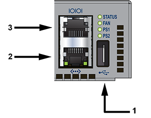
| 1 | USB port | 3 | Console serial port |
| 2 | Ethernet management port |
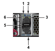
| 1 | System status LED | 3 | Activity status LED | 5 | USB port |
| 2 | Ethernet management port | 4 | Console serial port | 6 | Link status LED |
- Console (Serial) Port: Connect to a PC with the RJ-45 to DB-9 serial adapter cable. The switch uses the following default settings:
- 9600 baud
- No flow control
- 1 stop bit
- No parity bits
- 8 data bits
- Ethernet Management Port: Connect to 10/100/1000 management network with RJ-45 Ethernet cable.
- USB Port: The USB port may be used for software or configuration updates.
CAUTION: Excessive bending can damage interface cables, especially optical cables.
Flexion excessive peut endommager les câbles d’interface, notamment des câbles optiques.