Installing the Access Point
This chapter contains the stepwise procedure to install the access point (AP).
Zero-Configuration of the Access Point
Zero-configuration supports the following conditions:
-
The device must be in AP mode with background scanning on and without a configured SSID.
-
Set up a DNS entry for the wifi-security-server on all the DNS servers. This entry should point to the IP address of the server. By default, the AP looks for the DNS entry wifi-security-server.
- Place the AP on a subnet with DHCP-enabled.
Assign a static IP to the AP or change the settings to DHCP. Make a note of the MAC address and the IP address of the AP in a safe place before installing it in a hard-to-reach location. Locate the MAC address of the AP on a label at the bottom of the product.
Use the following steps to install the device:
Ceiling Mount the Access Point
Mounting the access point (AP) on the ceiling consists of the following steps:
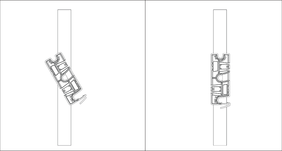
- Attach the bracket to the T -grid: Use the mounting bracket to install the AP on the ceiling. Attach the bracket to the T-grid and rotate the bracket so that it snaps on the T-grid. The bracket is now parallel to an arm of the T-grid. Ensure the bracket properly snaps to the T-grid, as shown below.
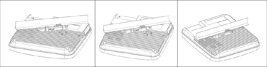
- Mounting the AP on the bracket: Place the first mounting post on the rear-side of the AP onto the lower notch of the bracket. Rotate the AP so that the center mounting post fits into the center notch on the bracket. Be sure all the mounting posts on the rear-side of the AP snap into the respective notches on the bracket. The mounting posts now properly fit in the respective notches of the bracket, and the AP mounted properly.
 Mounting Instructions using the Silhouette/Interlude Bracket Mount: The Silhouette/Interlude mounting bracket is not a part of the standard package and must be procured separately. The mounting instructions for the Silhouette/Interlude Bracket Mount are similar to the Standard Package Content's mounting instructions.Note: You should label the APs using MAC addresses or your convention. For example, use the AP serial numbers to easily identify the APs.
Wall Mount the Access Point
For instructions on wall mounting the access point, refer to Wall Mount the Access Point.
Connecting External Antennas to Access Point
Connect the external antennas to their respective ports using RP-SMA type connectors.
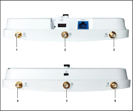
| 1 | Access radio. Dual-band antenna, 2.4 GHz, and 5 GHz bands. | 2 | Access radio. 5 GHz antenna. | 3 | Access radio. Dual-band antenna, 2.4 GHz, and 5 GHz bands. |
| 4 | Scanning radio. Dual-band antenna, 2.4 GHz,and 5 GHz bands. | 5 | Access radio. 5 GHz antenna. | 6 | Scanning radio. Dual-band antenna, 2.4 GHz, and 5 GHz bands. |
Connecting the Access Point to the Network
Connecting the Access Point using PoE
If you use a PoE injector, be sure to plug the data connection into a suitable switch port with proper network connectivity.
For PoE port details, see the Rear Panel section.
Power the Access Point On
You can power the access point (AP) on by plugging one end of the Ethernet cable into the PoE switch or injector and the other end into the Ethernet/PoE port on the AP. Be sure to turn on the PoE source.
As an alternative to PoE, you can insert a compatible power adapter plug into an AC power outlet and the other end into the power input port on the AP.
Using the Access Point with Power Adapter
Use a compatible power adapter (Arista SKU: PWR-AP-W4) to power the C-230E.
Warning: The C-230E is intended to be supplied with a UL-listed PoE power source suitable for use at 40ºC and whose output meets LPS requirements or PS2, with a rating of 48V DC(0.5A minimum). If you do not use PoE+, use only an AC power adapter supported by the C-230E access point (AP). This product is intended to be supplied by a Listed Direct Plug-In Power Unit marked “Class 2”, Listed Power Adapter, or DC power source marked “L.P.S.” (or “Limited Power Source”) and rated from 12 V DC, 2.5A minimum.
To power up the device with a power adapter, perform the following steps:- Plug the power cable into the DC power receptacle at the rear of the device.
- Plug the other end of the power cable into a 110V~240V 50/60 Hz AC power source.
- Wait until the device is ready. Refer to the LED status table.