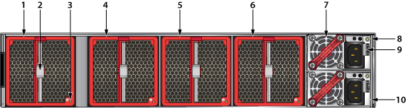
Rear Panel
This appendix displays the rear panel of all switches covered by this guide. Depending on the power supply and fan modules installed, the rear panel on your switch may appear slightly different.
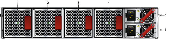
| 1 | Fan Module 1 | 3 | Fan Module 3 | 5 | Power Supply Module 1 |
| 2 | Fan Module 2 | 4 | Fan Module 4 | 6 | Power Supply Module 2 |
.png)
| 1 | Fan Module 1 | 4 | Fan Module 4 | 7 | Ground |
| 2 | Fan Module 2 | 5 | Power Supply Module 1 | ||
| 3 | Fan Module 3 | 6 | Power Supply Module 2 |
| 1 | Fan Module 1 | 5 | Fan Module 3 | 9 | Release |
| 2 | Release | 6 | Fan Module 4 | 10 | Power Supply Module 2 |
| 3 | Status LED | 7 | Power Supply Module 1 | ||
| 4 | Fan Module 2 | 8 | Status LED |