Front Panel
This section displays the front panel of all switches covered by this guide.
Note: All devices are designed to fit into a 19” rack. The appearance may be different than those shown based on the PSU and the fan modules used.
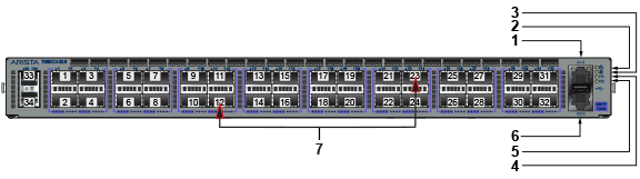
| 1 | Ethernet management port | 4 | Power supply 1 status LED | 7 | Port numbers |
| 2 | System status LED | 5 | Power supply 2 status LED | ||
| 3 | Fan status LED | 6 | Console serial port |
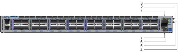
| 1 | Ethernet management port | 4 | Power supply 1 status LED | 7 | Console serial port |
| 2 | System status LED | 5 | Power supply 2 status LED | ||
| 3 | Fan status LED | 6 | USB port |
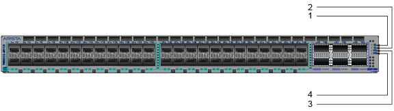
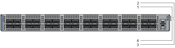
| 1 | System status LED | 3 | Power supply 1 status LED |
| 2 | Fan status LED | 4 | Power supply 2 status LED |
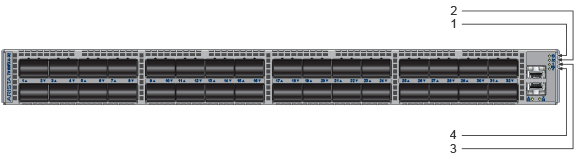
| 1 | System status LED | 3 | Power supply 1 status LED |
| 2 | Fan status LED | 4 | Power supply 2 status LED |
| 1 | System status LED | 3 | Power supply 1 status LED |
| 2 | Fan status LED | 4 | Power supply 2 status LED |