Cabling the Switch
Grounding the Switch
This section describes the importance of grounding the device to the data center ground.
Normally, the functional grounding of the switch is achieved through the input connection. If you would like to do additional grounding, proceed to the following instructions:
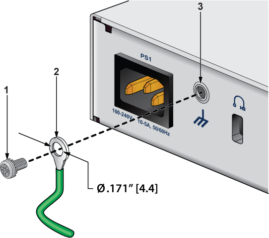
| 1 | Screw M4 (with washer) | 3 | Functional Grounding Point |
| 2 | Solder terminal lug |
- Ensure the rack is properly grounded and complies with ETSI ETS 300 253.
- Verify a good electrical connection to the grounding point on the rack (no paint or isolating surface treatment).
- Attach the solder terminal lug to an 18 AWG minimum grounding wire and connect it to the grounding point on the rear panel of the switch.
- Tighten the M4 screw to secure the lug to the grounding point.
- Connect the other end of the wire to the nearby grounded surface.
Connecting Power Cables
This section describes the installation requirements for connecting the power cables to the device.
-
Installation of this equipment must comply with local and national electrical codes. Consult with the appropriate regulatory agencies and inspection authorities to assure compliance if necessary.
Installation de cet équipement doit être conformes aux codes électriques locaux et nationaux. Si nécessaire, consulter les organismes de réglementation appropriés et des autorités de contrôle pour assurer la conformité.
-
Read all installation instructions before connecting the system to the power source.
Lire toutes les instructions d'installation avant de brancher le système à la source d'alimentation.
-
This equipment must be grounded. Never defeat the ground conductor.
Cet équipement doit être mis à la terre. Ne jamais modifier le conducteur de terre.
-
This unit requires overcurrent protection.
Cet appareil requiert une protection contre les surintensités.
Connecting AC Power
This section describes how to connect the AC power supply to the device.
The AC power supplies are internal to each switch.
Power requirements vary by switch. Refer to the Specifications section for information regarding your specific device.
The Rear Panel section displays the location of the power supplies for a specific device.
Use power supply cables that comply with IEC-320 and have a C13 plug.
Connecting Serial and Management Cables
This section describes the type of cables required to connect the device.
The following RJ-45 to DB-9 table lists the pin connections of the RJ-45 to DB-9 adapter cable.
| RJ-45 | DB-9 | RJ-45 | DB-9 | ||||
|---|---|---|---|---|---|---|---|
| RTS | 1 | 8 | CTS | GND | 5 | 5 | GND |
| DTR | 2 | 6 | DSR | RXD | 6 | 3 | TXD |
| TXD | 3 | 2 | RXD | DSR | 7 | 4 | DTR |
| GND | 4 | 5 | GND | CTS | 8 | 7 | RTS |
Connect the front panel ports as described below:
-
Console (Serial) Port: Connect to a computer with the RJ-45 to DB-9 serial adapter cable. The switch uses the following default settings:
- 9600 baud
- No flow control
- 1 stop bit
- No parity bits
- 8 data bits
- Ethernet Management Port: Connect to a 10/100/1000 management network with an RJ-45 Ethernet cable.
- USB Port: The USB port may be used for software or configuration updates.
Important:
Excessive bending can damage interface cables, especially optical cables.
Flexion excessive peut endommager les câbles d'interface, notamment des câbles optiques.