Status Indicators
This section discusses the following topics:
Front Indicators
The system and port status LED indicators are located on the front of the switches.
This section discusses the following topics:
Switch Indicators
The front panel LEDs on the chassis's right side display the system, fan, and power supply status. The Front Panel displays the front panels of all switches covered by this guide.
The System Status Indicators image displays the CCS-720XP-96ZC2 front panel LEDs.
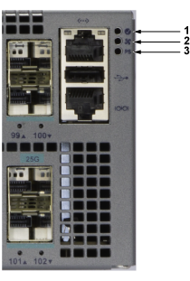
| 1 | System status LED | 2 | Fan status LED | 3 | PSU status LED |
| LED Name | LED State | Device Status |
|---|---|---|
| System Status | Blinking Green | System powering up. |
| Green | All power supplies and fans are operating normally. | |
| Blue | The locator function is active. | |
| Red | A power supply or fan is missing or in a failed state. | |
| Fan Status | Green | All fans are operating normally. |
| Red | One or more fans have yet to be inserted or have failed. | |
| Power Supply Status | Off | The power supply is not inserted or powered. |
| Green | The power supply is operating normally. | |
| Red | The power supply has failed. |
Port Indicators
Port LEDs near their corresponding ports provide a link and operational status. The Port LED image displays the Port LED location on the CCS-720XP-96ZC2 switch. The Front Panel displays the port LED locations of all switches this guide covers.
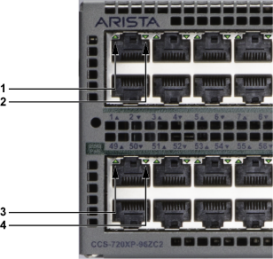
| 1 | Port status LED (upper port) | 3 | Port status LED (upper port) |
| 2 | Port status LED (lower port) | 4 | Port status LED (lower port) |
Port LED States provide status conditions that correspond to port LED states. Port LED behavior for QSFP+ and SFP+ ports is consistent.
| LED State | Status |
|---|---|
| Off | The port link is down. |
| Green | The port link is up. |
| Yellow | The port is software disabled. |
| Flashing Yellow | The port failed diagnostics. |
Rear Status Indicators
Fan and power supply modules are accessed from the rear panel. Each fan and power supply module contains an LED that reports the module status. Rear Panel displays the rear panel of all switches covered by this guide.
Fan Status LEDs are on the fan modules, as displayed in Fan Status LED.
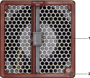
| 1 | Release | 2 | Fan module status LED |
The module installation indicator is green when the fan module is properly installed or red when the module is not fully installed. Fan Status LED States provide status conditions that correspond to fan status LED states.
| LED State | Status |
|---|---|
| Off | The fan module is inserted but not receiving power – it may not be properly seated. |
| Green | The fan is operating normally. |
| Red | The fan has failed. |
The power supply status LEDs are on the modules, as shown in the AC Power Supply Status LED.
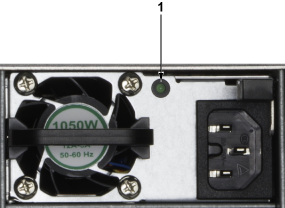
| 1 | PSU module status LED |
The AC Power Supply Status LED States provides conditions corresponding to power supply status LED states.
| Power Supply State | PWR-1021-AC-RED |
|---|---|
| Input power present Normal operation | Green |
| Input power present Power Supply fault | ON/OFF: ON when PSU output is ON, OFF when PSU Output is OFF |
| Input power present Power Supply FAN fault | FLASH 800 ms ON / 800 ms OFF |
| No Input power Supply installed in chassis | OFF |
| Input power present Supply not installed in chassis | Green |