Maintenance and Field Replacement
This appendix describes the process for replacing switch components. You must ensure that at least one of the secondary grounding pads located on the front panel of the chassis is connected to the data center ground. While working on the switches, use grounded, anti-static wrist straps connected to one of the attach points on the switch for grounding yourself and preventing ESD damage to the switch.
Power Supplies
Removing AC Power Supply
- Put on a grounded, anti-static ESD strap.
- Unplug the cable from the PSU.
- Squeeze the latch release.
- Remove the power supply from the switch using the power supply latch release and handle.
Installing AC Power Supply
- Put on a grounded, anti-static ESD strap.
- Unpack the new power supply.
- Insert the new power supply into the empty power supply slot.
- After you insert the power supply, push gently on the power supply until the power supply is fully seated.
- Connect the power cord to the power supply.
- Connect to the power source.
- Verify normal operation using the LED indicators for your switch PSU Status LED.
Fan Module
The fan modules are hot-swappable and N + 1 redundant. They are accessible from the rear of the switch (Rear Panel). You must take into account that the module you are inserting is compatible with the switch and the module that you are replacing. Perform the following steps to remove and replace a fan module.
Removing Fan Module
- Put on a grounded, anti-static ESD strap.
- Use the release lever to unseat the fan module.
- Use the handle to pull out the fan module.
Installing Fan Module
- Put on a grounded, anti-static ESD strap.
- Unpack the module to be installed.
- Slide the fan module into the slot until it is completely seated.
- Verify that the module is operating normally (Fan Status LED).
- Use the show environment cooling command to further verify normal operation.
Supervisor Module
The supervisor modules are hot-swappable. They are accessible from the front of the switch. You must take into account that the module you are inserting is compatible with the switch and the module that you are replacing. Use the following procedure to remove and replace a supervisor module. For the supervisor module locations for your device, refer to the Front Panel.
Removing Supervisor Module
- Put on a grounded ESD strap.
- Use the release handles on the Supervisor card to unseat it.
- Slide supervisor module out of the slot.
Removing Supervisor Module Blank
Installing Supervisor Module
- Put on a grounded, anti-static ESD strap.
- Unpack the supervisor module to be installed.
- Slide supervisor module into slot until it is completely seated.
- Verify that the module is operating normally (Supervisor Status LED).
linecards
The linecards are hot-swappable. They are accessible from the front of the switch. You must take into account that the linecard you are inserting is compatible with the switch and the linecard that you are replacing. Use the following procedure to remove and replace a linecard. If you are adding a new linecard, remove the blank from the linecard slot and install the new linecard. For the linecard locations on your switch, refer to the Front Panel. Figure 1 shows linecards with the seating or ejector mechanisms along with some fully seated linecards.
.png)
| 1 | Linecard | 3 | Ejector lever (linecard seated correctly) |
| 2 | Ejector mechanism (lever and handle) | 4 | Ejector lever (linecard not seated) |
Removing a Linecard
- Put on a grounded, anti-static ESD strap.
- Move the left and right handle outwards until the ejector lever releases the linecard.
- Slide the linecard out using care as the linecard could be heavy.
Removing Linecard Blank
Installing a Linecard
Switchcards
The switchcards are hot-swappable and 1 + 1 redundant. They are accessible from the rear of the switch (Rear Panel). You must take into account that the switchcard you are inserting is compatible with the switch and the switchcard that you are replacing. Use the following procedure to remove and replace a switchcard. For the switchcard locations on your switch, refer to the Rear Panel.
Removing Switchcard
- Pull the switchcard out gently once released.
Note: When the switchcard and fan assembly is removed, a metal cover swings into place (Figure 2).
Figure 2. 758 Rear View with one Switchcard Installed
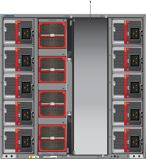
1 SC2 cover
Installing Switchcard
- Verify that the switchcard is operating normally (Switchcard Status LED).
Figure 3 shows switchcard installation. The switchcard on the right is fully seated with the latch closed.
Figure 3. 758 Switchcard Installation
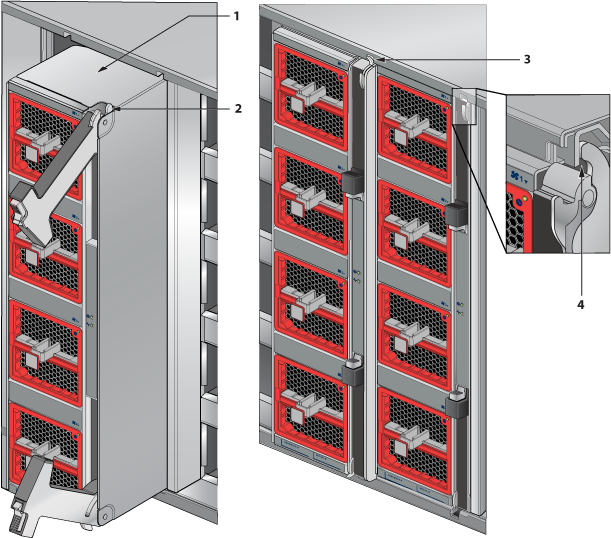
1 Switch Card 3 Ejector (switchcard not seated) 2 Ejector mechanism (handle and latch) 4 Ejector latch (closed)