RoHS Information
This section provides the China and Taiwan RoHS information for the switches this guide covers.
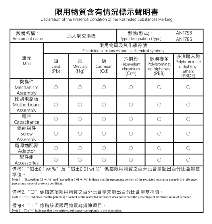
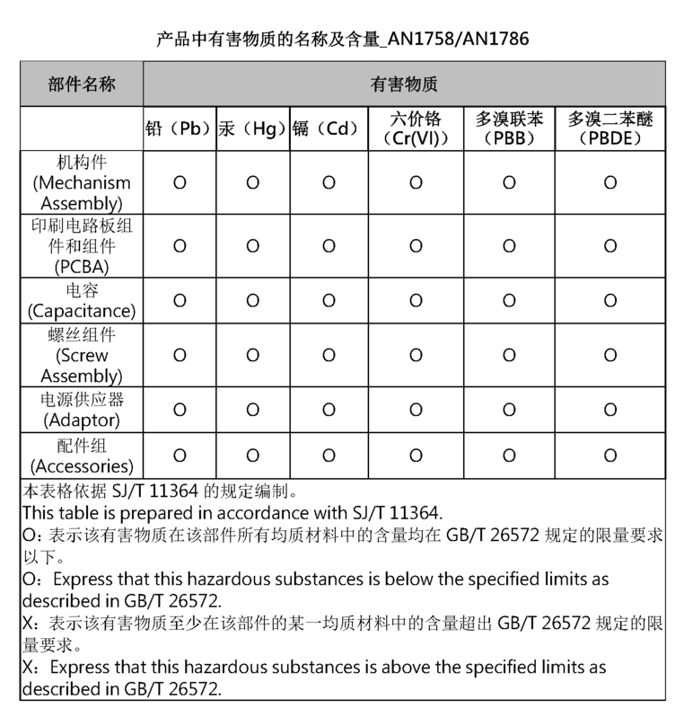
This section provides the China and Taiwan RoHS information for the switches this guide covers.
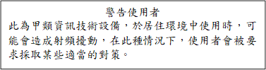
This section provides the Taiwan BSMI Class A Statement information for the switches this guide covers.
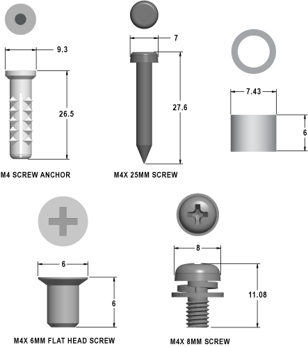
This section describes the detailed screw size information required.
This section lists the Regulatory Model Numbers (RMNs) of the Ethernet switches described in this guide.
|
SKU |
Regulatory Model Number (RMN) |
|---|---|
|
CCS-710P-12 |
AN1758 |
|
CCS-710P-16P |
AN1786 |
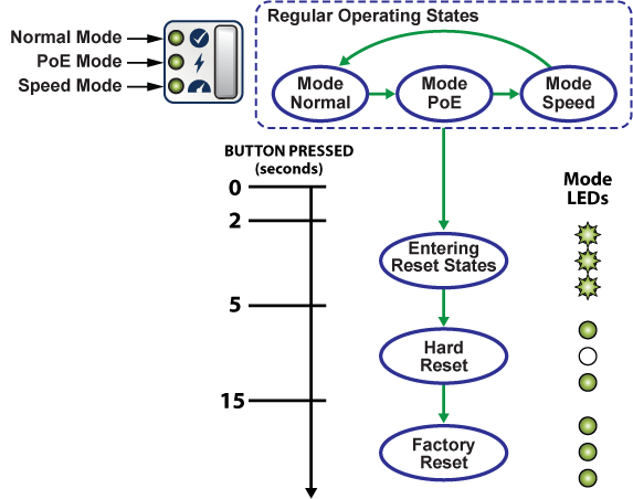
This section discusses the functionality of the mode button located on the front panel of the switch.
The section discusses the rear panel of the Ethernet Switch.
The CCS-710P-12 and CCS-710P-16P rear panels include the following key components:
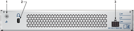
| 1 | Functional Grounding Point | 3 | Power Supply |
| 2 | Kensington lock hole |
This section discusses the front panel of the Ethernet Switch.
The CCS-710P-12 front panel includes the following key components:
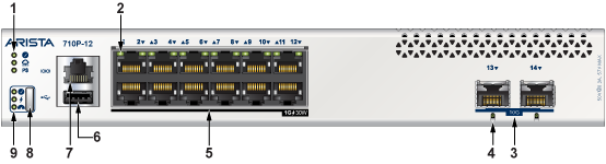
| 1 | System Status LEDs | 6 | USB port |
| 2 | Port LEDs | 7 | Console port |
| 3 | SFP+ ports | 8 | Mode Button |
| 4 | SFP+ port LEDs | 9 | Mode Status LEDs |
| 5 | Ethernet RJ45 ports with 30W PSE |
The CCS-710P-16P front panel includes the following key components:
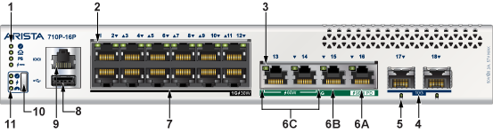
| 1 | System Status LEDs | 7 | Ethernet RJ45 ports with 30W PSE |
| 2 | Port LEDs | 8 | USB port |
| 3 | 5GE port LEDs | 9 | Console port |
| 4 | SFP+ port LEDs | 10 | Mode button |
| 5 | PoE Ports | 11 | Mode status LEDs |
| 6 |
6A: Uplink 5G Ethernet RJ45 port with 90W PD 6B: Uplink 5G Ethernet RJ45 port 6C: 5G Ethernet RJ45 ports with 60W PSE |
This section lists the installation parts contained in the switch accessory kit. Each device has an accessory kit that contains the necessary parts to install the switch.
The following accessories are available along with the device:
L-bracket (left)
L-bracket (right)
Rubber feet
Power adapter
Flat head screw M4x6mm
Power cable (specified during time of purchase as it's country-specific or no power cord)
The following are the optional accessories and should be ordered separately if required:
| Spare SKU | Description |
|---|---|
| KIT-CCS-710 | Accessory Kit for Arista 710P Series switches |
| KIT-CCS-710-DIN | DIN-Rail Mount Kit for Arista 710P Series switches |
| KIT-CCS-710-RM | Rack Mount Kit for Arista 710P Series switches |
| KIT-CCS-710-MGN | Magnet Mount Kit for Arista 710P Series switches |
The following is the list of SKU numbers related to the respective product.
|
SKU |
Product Description |
|---|---|
|
CCS-710P-12 |
Arista Power Adapter, 150W, PoE, AC (Spare) |
|
CCS-710P-16P |
Arista Power Adapter, 280W, PoE, AC (Spare) |
This section describes the front panel LED status of the device.

|
LED Name |
LED State |
Device Status |
|---|---|---|
|
System Status LED |
Off |
No power or in the midst of a power cycle. |
|
Blinking Green |
The system is powering up. |
|
|
Green |
The system is operating in a normal initialization sequence. Normal operations. |
|
|
Blue |
The locator function is active. |
|
|
Amber |
The system is malfunctioning. System is overheating, or temperature sensors have recorded passing the software-defined critical threshold. The switch will automatically execute a “graceful shutdown” shortly. |
|
|
Cloud Connect Status LED |
Off |
The system is not connected to the cloud. |
|
Green |
The system is connected to the cloud. |
|
|
Amber |
There is problem connecting to the cloud. |
|
|
Power Supply Status LED |
Off |
The power supply adapter is not available. |
|
Green |
The power supply adapter is fully functional. |
|
|
Amber |
The power supply adapter has a fault. |
|
|
PD Port Power Status LED (710P-16P only) |
Off |
The PD port power is not available. |
|
Green |
The PD port power is fully functional. |
|
|
Amber |
The PD port power has a fault. |
|
|
Port Normal Mode LED |
Off |
Normal mode is not selected. |
|
Green |
The port LED is selected to indicate the port link status (normal mode). |
|
|
Port PoE Mode LED |
Off |
PoE mode is not selected. |
|
Green |
The port LED is selected to indicate the port PoE status. |
|
|
Port Speed Mode LED |
Off |
Speed mode is not selected. |
|
Green |
Port LED is selected to indicate the port speed. |
|
Port LEDs |
Normal Mode |
PoE Mode |
Speed Mode |
|||
|---|---|---|---|---|---|---|
|
1GE RJ45 Port LED (P1 to P12) |
Off |
Port link is down |
Off |
No PoE |
Blinking Amber |
10M |
|
Green |
Port link is up |
Blinking Amber |
15W |
Amber |
100M |
|
|
Amber |
Port is software disabled |
Amber |
30W |
Green |
1G |
|
|
5GE RJ45 Port LED (P13 to P14, 710P-16P only) |
Off |
Port link is down |
Off |
No PoE |
Blinking Amber |
1G |
|
Green |
Port link is up |
Blinking Amber |
15W |
Amber |
2.5G |
|
|
Amber |
Port is software disabled |
Amber |
30W |
Green |
5G |
|
|
Blinking Green |
60W |
|||||
|
5GE RJ45 Port LED (P15, 710P-16P only) |
Off |
Port link is down |
Off |
No PoE |
Blinking Amber |
1G |
|
Green |
Port link is up |
Amber |
2.5G |
|||
|
Amber |
Port is software disabled |
Green |
5G |
|||
|
5GE RJ45 Port LED (P16, 710P-16P only) |
Off |
Port link is down |
Off |
No PoE |
Blinking Amber |
1G |
|
Green |
Port link is up |
Blinking Green |
60W |
Amber |
2.5G |
|
|
Amber |
Port is software disabled |
Green |
90W |
Green |
5G |
|
|
SFP+ Port LED (P13 to P14, 710P-12 / P17 to P18, 710P-16P) |
Off |
Port link is down |
Off |
No PoE |
Blinking Amber |
100M |
|
Green |
Port link is up |
Amber |
1G |
|||
|
Amber |
Port is software disabled |
Green |
10G |
|||
Arista switches ship from the factory in Zero Touch Provisioning (ZTP) mode. ZTP configures the switch without user intervention by downloading a startup configuration file or a boot script from a location specified by a DHCP server. To manually configure a switch, ZTP is bypassed. The initial configuration provides one username (admin) that is accessible only through the console port because it has no password.
When bypassing ZTP, initial switch access requires logging in as admin, with no password, through the console port. Then you can configure an admin password and other password protected usernames.
This manual configuration procedure cancels ZTP mode, logs into the switch, assigns a password to the admin, assigns an IP address to the management port, and defines a default route to a network gateway.