Quick Start Guide
Edge Threat Management
Appliance
CCA-ETM-Q8W
Arista Networks

www.arista.com

DOC-06006-02

Headquarters
5453 Great America Parkway
Santa Clara, CA 95054, USA
+1-408 547-5500
www.arista.com
Support
+1-408 547-5502
+1-866 476-0000
This email address is being protected from spambots. You need JavaScript enabled to view it.
Sales
+1-408 547-5501
+1-866 497-0000
This email address is being protected from spambots. You need JavaScript enabled to view it.
© Copyright 2023 Arista Networks, Inc. The information contained herein is subject to change without notice. Arista Networks and the Arista logo are trademarks of Arista Networks, Inc., in the United States and other countries. Other product or service names may be trademarks or service marks of others.

Overview

Scope

This guide is intended for properly trained service personnel and technicians who need to install the following Arista appliance:

CCA-ETM-Q8W

Important:

Only qualified personnel should install, service, or replace this equipment.

Seul le personnel qualifié doit installer, service, ou remplacer cet équipement.

Receiving and Inspecting the Equipment

Upon receiving the appliance, inspect the shipping boxes and record any external damage. Retain packing materials if you suspect that part of the shipment is damaged; the carrier may need to inspect them.

If the boxes were not damaged in transit, unpack them carefully. Ensure that you do not discard any accessories that may be packaged in the same box as the main unit.

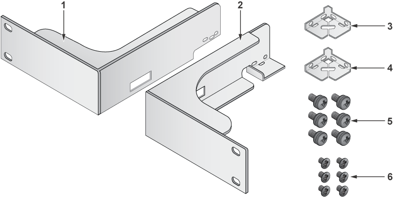
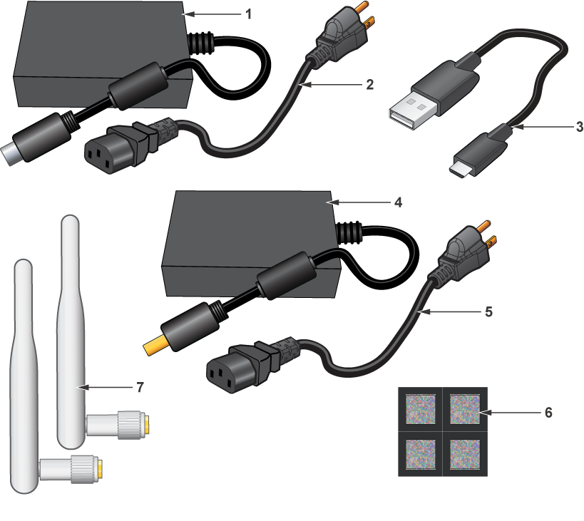
Inspect the packing list and confirm that you received all listed items. Compare the packing list with your purchase order. Parts List provides a list of components included with the appliance.

Installation Process

The following tasks are required to install and use the appliance:


  1. Select and prepare the installation site (Site Selection).
  2. Assemble the installation tools listed (Tools and Parts Required for Installation).
  3. Install the appliance (Mounting the Appliance).
  4. Connect the appliance to the power source and network appliances (Cabling the Appliance).
  5. Configure the appliance (Configuring the Appliance).
    Important:

    Class 1 Laser Product: This product has provisions to install Class 1 laser transceivers which provide optical coupling to the communication network. Once a Class 1 laser product is installed, the equipment is a Class 1 Laser Product. The customer is responsible for selecting and installing the Class 1 laser transceiver and for insuring that the Class 1 AEL (Allowable Emission Limit) per EN/IEC 60825, CSA E60825-1, and Code of Federal Regulations 21 CFR 1040 is not exceeded after the laser transceiver have been installed. Do not install laser products whose class rating is greater than 1. Refer to all safety instructions that accompanied the transceiver prior to installation. Only Class 1 laser appliances, certified for use in the country of installation by the cognizant agency are to be utilized in this product.


    Produit Laser de classe 1: Ce produit a des dispositions pour installer des émetteurs-récepteurs de laser de classe 1 qui offre de couplage au réseau de communication optique.Une fois un produit laser de classe 1 est installé, l'équipement est un produit Laser de classe 1 (Appareil à Laser de Classe 1).Le client est responsable pour sélectionner et installer l'émetteur/récepteur de laser de classe 1 et pour assurer que la classe 1 AEL (limite d'émission admissible) par EN/IEC 6-825, CSA E60825-1, et Code des règlements fédéraux 21 CFR 1040 ne soit pas dépassée après avoir installé l'émetteur/récepteur de laser. Ne pas installer des appareils à laser dont la cote de classe est supérieure à 1.Voir toutes les consignes de sécurité qui ont accompagné l'émetteur-récepteur avant l'installation. Seuls appareils laser de classe 1 certifiés pour une utilisation dans le pays d’installation par l’organisme compétent doivent être utilisées dans ce produit.

    Important:

    Ultimate disposal of this product should be handled in accordance with all national laws and regulations.

    Aucune pièce réparable par l'utilisateur à l'intérieur. Confiez toute réparation à un technicien qualifié.
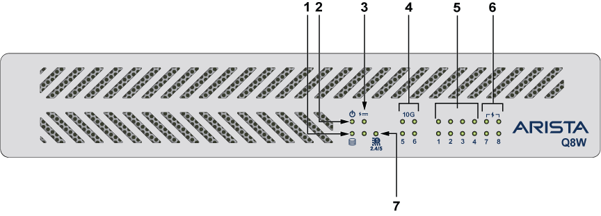
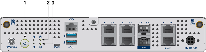
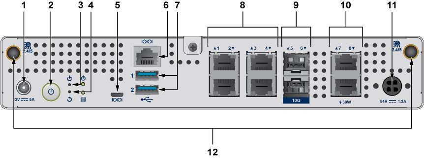
Obtaining Technical Assistance

Any customer, partner, reseller, or distributor holding a valid Arista Service Contract can obtain technical support in any of the following ways:

Specifications

This section lists the specifications of the CCA-ETM-Q8W.

Table 1. Appliance Specifications (Dimensions and Weights)
Appliance Size (W x D xH) Weight
CCA-ETM-Q8W 250mm x 252mm x 44mm 2.5 kg


Table 2. Appliance Specifications (Operational and Storage)
Appliance Operating Temperature, Relative Humidity Storage Temperature, Relative Humidity Operating Altitude
CCA-ETM-Q8W 0° – 40°C

20% – 80% RH

-10° – 70°C

5% – 95% RH

up to 5000 meters


Table 3. Appliance Specifications (Power Input)
Power Source Ratings
12V 60W Power Adapter 100-240V, 1.8A, 50-60Hz
54V 65W PoE Power Adapter 100-240V, 1.8A, 50-60Hz

Preparation

Site Selection

The following criteria should be considered when selecting a site to install the appliance.

  • Temperature and Ventilation: For proper ventilation, install the appliance where there is ample airflow to the front and back of the appliance. The ambient temperature should not go below 0° or exceed 40°C.
    Important: To prevent the appliance from overheating, do not operate it in an area where the ambient temperature exceeds 40°C (104°F).

    Pour empêcher l’interrupteur de surchauffe, ne pas utiliser il dans une zone où la température ambiante est supérieure à 40°C (104°F).

  • Airflow Orientation: The airflow of the appliance travels from front to back.
  • Rack Space: Install the appliance in a 19" rack or cabinet. The appliance height is 1 RU. The rack mounting kit provides mounting brackets for two-post racks.

When mounting the appliance in a partially filled rack, load the rack from bottom to top, with the heaviest equipment at the bottom. Load the appliance at the bottom if it is the only item in the rack.

  • Other Requirements: Select a site where liquids or objects cannot fall onto the equipment and foreign objects are not drawn into the ventilation holes. Verify these guidelines are met:
    • Clearance areas to the front and rear panels allow for unrestricted cabling.
    • All front and rear panel indicators can be easily read.
    • Power cords can reach from the power outlet to the connector on the rear panel.
      Important: All power connections must be removed to de-energize the unit.

      Toutes les connexions d’alimentation doivent être enlevées pour hors tension l’appareil.

Tools and Parts Required for Installation

These are the tools and parts needed to install the CCA-EMT-Q8 appliance in a rack.

In addition to the rack mount kit SKU KIT-ETM-NGQ8, rack mount installation requires:
1 #2 Phillips screwdriver

Electrostatic Discharge Precautions

Observe these guidelines to avoid ESD damage when installing or servicing the appliance:
  • Assemble or disassemble equipment only in a static-free work area.
  • Use a conductive work surface (such as an anti-static mat) to dissipate static charge.
  • Wear a conductive wrist strap to dissipate static charge accumulation.
  • Minimize handling of assemblies and components.
  • Keep replacement parts in their original static-free packaging.
  • Remove all plastic, foam, vinyl, paper, and other static-generating materials from the work area.
  • Use tools that do not create ESD.

Mounting the Appliance

This appliance can be installed on a desktop or in a rack. The following topics are covered in this chapter:


Desktop Installation


To install the appliance on a desktop, complete the following steps:
  1. Attach the rubber feet to the bottom corners of the appliance.
  2. Connect the cables according to Cabling the Appliance.

Rack Mounting the Appliance

To mount the appliance onto a two-post rack, assemble the mounting brackets to the chassis, then attach the brackets to the rack posts. The rack mount parts are sold separately (SKU KIT-ETM-NGQ8).

Parts required for rack mount installation:

1 Left mounting bracket
2 Right mounting bracket
3, 4 Power adapter mounting brackets (2)
5 Phillips pan head M4 screws with lock washers (6)
6 Phillips flat head M3 screws (6)
  Cable tie straps (4)

Attaching Mounting Brackets to the Appliance

This procedure attaches mounting brackets to the appliance.


  1. Using three M3 flat head screws and one M4 pan head screw with lock washer for each flange, attach the rack mount flanges to each side of the front of the appliance. The M4 pan head screw with lock washer should be attached in front of the rearmost M3 flat head screw.
  2. Proceed to installation of power adapters as described in Installing the Power Adapters.

Installing the Power Adapters

Installing the power adapter brackets is required for rack mount installation. The rack mounting brackets must be installed first. The appliance has two power adapters. The 54V power adapter is installed on the left side of the appliance, close to the 54V power input. The 12V power adapter is installed on the right side of the appliance. The illustration shows the 12V power adapter installation on the right side of the appliance. The 54V power adapter is installed in the same way on the left side of the appliance.

  1. Install the rack mount brackets (4) as described in Attaching Mounting Brackets to the Appliance.
  2. Align mounting bracket with holes on side of appliance.
  3. Secure mounting bracket (3) with M4 screws with lock washers.
  4. Place power adapter (2) on top of mounting bracket and rear end of side rack mount bracket.
  5. Secure power adapter with cable tie straps (1).
  6. Repeat procedure with other power adapter on other side of appliance.

Inserting the Appliance into the Rack

This procedure attaches the appliance to the rack.

  1. If the mounting brackets and power adapters have not been installed, install them first, as described in Attaching Mounting Brackets to the Appliance and Installing the Power Adapters.
  2. Lift the appliance into the rack. Position the mounting brackets against the rack posts.
  3. Select mounting screws that fit your equipment rack.
    Note: Rack mounting screws are not included.
  4. Attach the brackets to the rack posts.

Cabling the Appliance

For all installations:

  1. Plug in the 12V power adapter to a power source and connect it to the DC 12V power input on the rear panel.
  2. Plug in the 54V power adapter to a power source and connect it to the DC 54V power input on the rear panel.
  3. Connect a WiFi antenna to the WiFi antenna on the left side of the rear panel.
  4. Connect a WiFi antenna to the WiFi antenna on the right side of the rear panel.
  5. Connect an Ethernet cable from your Internet modem or router to Port 1.
  6. Connect an Ethernet cable from your local network to Port 2.
  7. Power on the system by pressing the power button located on the rear panel next to the power input.
  8. Allow approximately two minutes for the system to initialize before continuing with the next steps.

Configuring the Appliance

You can manage your appliance using the Edge Threat Management Dashboard or from the local network.

From Edge Threat Management Dashboard
  1. Navigate your web browser to https://edge.arista.com/cmd.
  2. Log in with your Edge Threat Management Dashboard account, or click Create Account to set up an account.
  3. Navigate to the Appliances screen and click Add.
  4. Enter the serial number located on the bottom of your appliance.
  5. Click Add to confirm the new appliance.
  6. After the appliance successfully adds to your account, you can select it from the list of appliances.
  7. Click Remote Access to connect to the administration of your new appliance.
  8. Continue to the setup wizard.
From the Local Network
  1. From your management computer, check the network status of your system and confirm that you receive an IPv4 address in the subnet of 192.168.2.0/24 (such as, 192.168.2.100).

  2. In a browser, navigate to http://192.168.2.1.

  3. Accept the SSL certificate notice in your browser and continue to the setup wizard.

Status Indicators

The following topics are covered in this appendix:

Front Indicators

The front status indicators are located at right half of the front panel.
Figure 1. CCA-ETM-Q8W Front Status Indicators
1 Hard drive 5 1 Gb port
2 Power 6 1 Gb PoE port
3 PoE 7 WiFI
4 10 Gb port    

Rear Indicators

This section shows the rear indicators for appliances listed in this guide.

Figure 2. CCA-ETM-Q8W Rear Indicators


1 Power button
2 Power
3 Hard drive

Parts List

Package Contents

Figure 1. CCA-ETM-Q8W Parts Included
1 12V power adapter 5 Power cord
2 Power cord 6 Rubber feet
3 USB cable 7 WiFi antennas
4 54V power adapter    

Rear Panel


This appendix displays the rear panel of all appliances covered by this guide.

Figure 1. CCA-ETM-Q8W Rear Panel

1 12V power port 5 Micro USB console port 9 10 Gbit SFP+ ports
2 Power button 6 Console port 10 1Gb PoE ports
3 Reset button 7 USB ports 11 54v power port
4 Factory reset button 8 1Gb LAN ports 12 WiFi antenna ports


Regulatory Model Numbers

This appendix covers the Regulatory Model Number for the appliances in this guide.

Regulatory Model Number (RMN) Product Number(s)
AN2205, CAD-0263-5801-E90 CCA-ETM-Q8W