Rack Mounting the Router
This section provides instructions on how to mount the router in different ways.
The following topics are covered in this section:
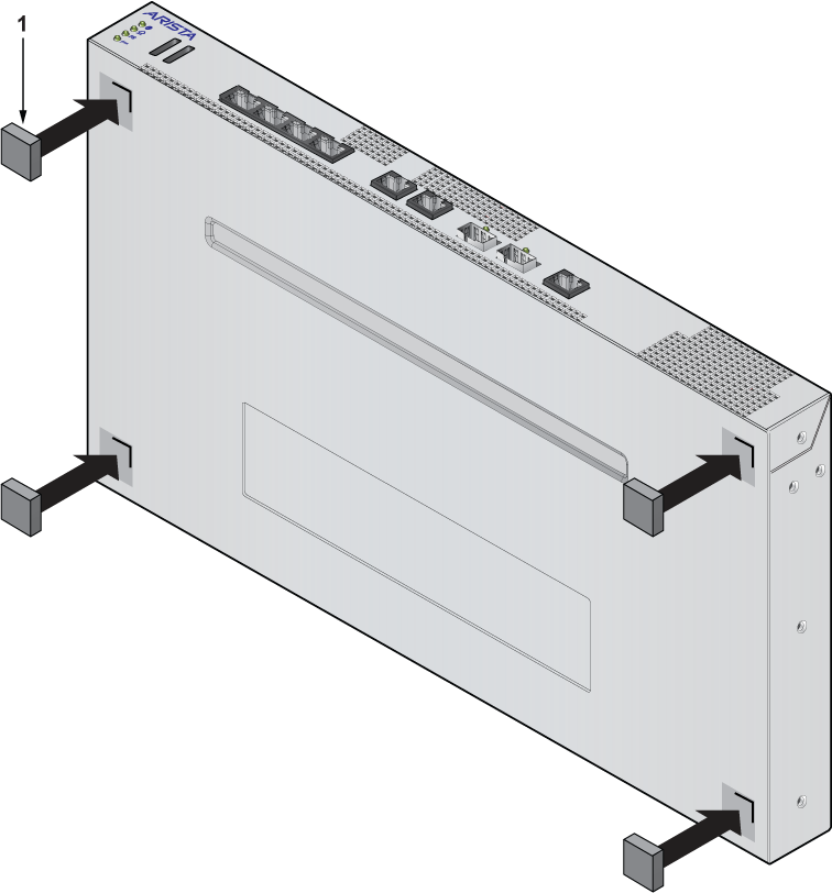
Desktop Mount
This section provides instructions to mount the router on the desktop or any flat surface.
|
1 |
Rubber feet |
Two-post Rack Mount
This section provides instructions for mounting the router in a two-post rack.
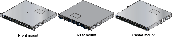
Two Three-hole Mounting Brackets
Each chassis has attachment pins that align with bracket holes. Pin orientation is symmetric and equidistant, supporting bracket placements where the flange is flush with the front panel, flush with the rear panel, or not flush with either panel. Each bracket hole includes a critical opening for placing the bracket flush with the chassis and then locking it into place.
Goupilles de fixation doivent être bloquer tous les trois trous de la bride supérieure.
To mount the router in a two-post rack, proceed to the following topics:
Attaching Mounting Brackets to the Chassis
This section describes the steps to attach mounting brackets to the router chassis.
.png)
| 1 | Bracket clip installation (left side) | 2 | Front mount |
| 3 | Bracket clip installation (left side) | 4 | Flat head screws |
- Slide the bracket toward the front flange until the bracket clip locks with an audible click.
The following figure shows the correct bracket attachment for a front mount.
Figure 4. Attaching the Mounting Brackets to the Chassis
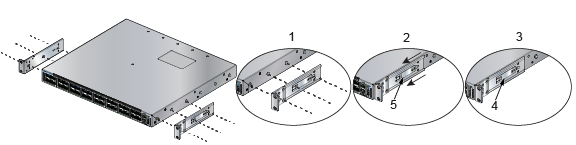
1 Align the mounting brackets with the attachment pins to obtain the desired mounting position. 4 Bracket clip (attached) 2 Place the bracket flush on the chassis with attachment pins protruding through critical openings. 5 Bracket clip (aligned) 3 Slide the bracket toward the front flange until the bracket clip locks with an audible click. To remove the mounting bracket from the chassis, lift the front edge of the mounting bracket clip with a flat-head screwdriver and slide the bracket away from the front flange (opposite from the installation direction).
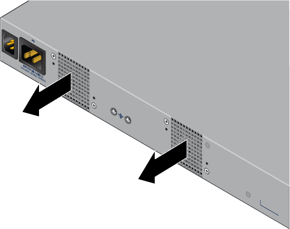
Inserting the Router into the Two-post Rack
- Attach the bracket flanges to the rack posts.
Figure 5. Inserting the Router into the Rack
.png)
1
Attaching chassis securely to rack with the screws
2
Aligning the bracket with the rack
Four-post Rack Mount (Optional)
This section provides instructions for mounting the router in a four-post rack.
The router is mounted onto a four-post rack by assembling two rails onto the rear posts, sliding the router onto the rails, and securing the router to the front posts.
- Two six-hole mounting brackets
- Two rail rods
- Two rail slides
Each chassis side has attachment pins that align with bracket holes. Pin orientation is symmetric and equidistant, supporting bracket placements where the flange is flush with the front panel, flush with the rear panel, or not flush with either panel. Each bracket hole includes a critical opening for placing the bracket flush with the chassis and then locking it into place.
Goupilles de fixation doivent être lock au moins cinq des trous du six support.
The following figure displays proper bracket mount configuration examples for a four-post mount:
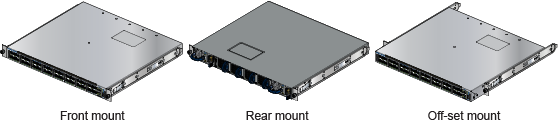
To mount the router in a four-post rack, proceed to the following topics:
Attaching Mounting Brackets to the Chassis
This section describes the steps to attach the mounting brackets to the chassis.
.png)
| 1 | Mounting bracket (left) | 3 | Mounting bracket (right) |
| 2 | Front mount | Flat head screws |
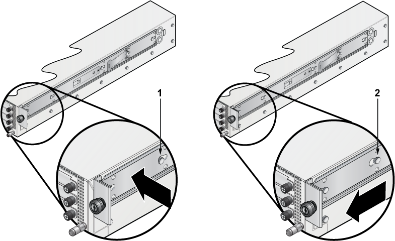
| 1 | Bracket clip before it is locked in the specified place. | 2 | Bracket clip after it is locked in the specified place. |
Assembling the Rails into the Rack
This section describes the steps to attach the mounting brackets to the chassis.
Rail rods and rail slides assemble into identical rails. Each rail connects a front post to a rear post. When the rails are installed, the router slides through the rails into the rack.
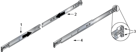
| 1 | Rail slide | 3 | Rack plugs |
| 2 | Rail rod | 4 | Rail (assembled) |
- Attach the rail to the rack post using the screws and rack plugs in the dedicated slots.
Figure 10. Attaching the Rails to the Four-post Rack
.png)
1 Rack plugs (rear) 3 Rack plugs (front) 2 Screw (rear) 4 Screw (front)
Inserting the Router into the Four-post Rack
After the rails are installed, the router slides into the rack. Each bracket includes a thumb screw that attaches the router to the rail.
- Lift the router and insert it into the four-post rack by sliding the mounting brackets through the rails.
Figure 11. Inserting the Router onto the Rails
.png)
1 Rail rod 3 Rail slide 2 Front mount 4 Rack plug