RoHS Information
This appendix provides Taiwan and China RoHS information for the Ethernet switches described in this guide.
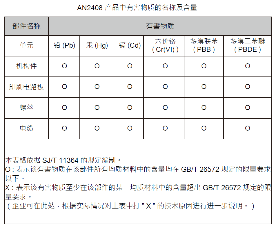
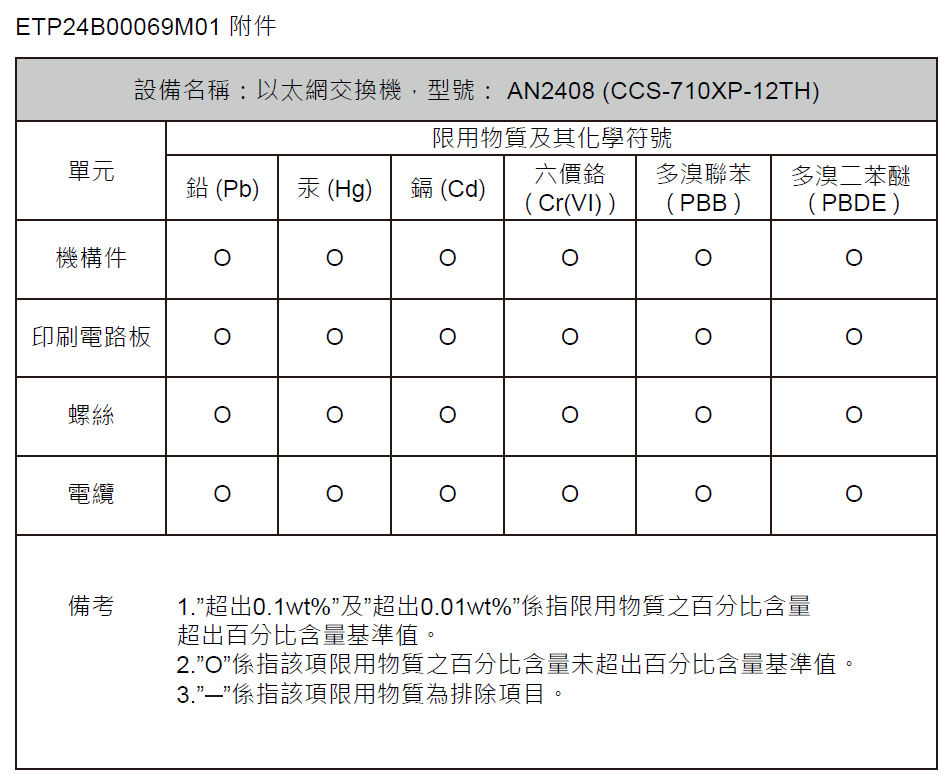
This appendix provides Taiwan and China RoHS information for the Ethernet switches described in this guide.
This appendix provides BSMI Class A Statement information for switches described in this guide.
This section lists the Regulatory Model Numbers (RMNs) of the Ethernet switches described in this guide.
| Product Number | Regulatory Model Number (RMN) |
|---|---|
|
CCS-710XP-12TH-2S |
AN2408 |
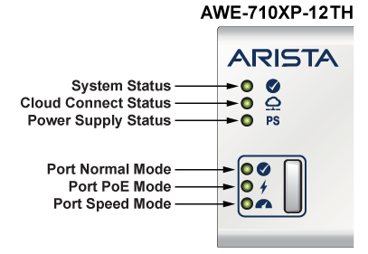
This section describes the functionality of the mode button located on the front panel of the switch.
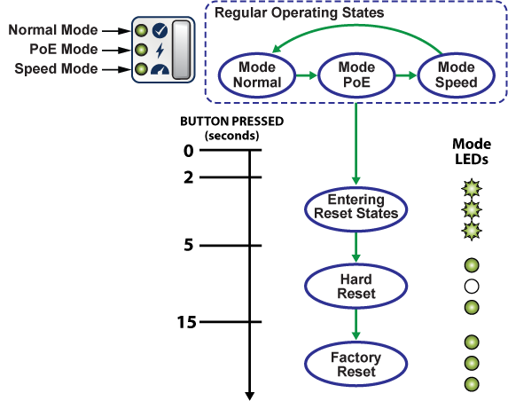
The mode button port LEDs will transition to different modes as listed below when the user presses the mode button for less than 2 seconds, and the same is indicated by the corresponding mode status LED.
In addition to controlling the port/mode LEDs, the button can trigger other actions, including a hard reset and a factory reset. To access these actions, it is required to long-press the button as shown in the Figure 1 - Mode Button States.
The section describes the rear panel of the Ethernet Switch.
The CCS-710XP-12TH-2S rear panel includes the following key components:
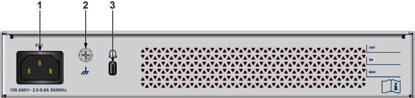
| 1 | Power supply | 3 | Kensington lock |
| 2 | Functional Grounding Point |
This section describes the front panel of the Ethernet Switch.
The CCS-710XP-12TH-2S front panel includes the following key components:
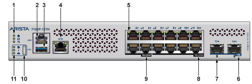
| 1 | System Status LEDs | 7 | SFP+ Port LEDs |
| 2 | Console Port | 8 | 8x1G 30W PoE Ports |
| 3 | USB Port | 9 | 4x1G 60W PoE Ports |
| 4 | RJ45 Ethernet Management Port | 10 | Mode Button |
| 5 | Port LEDs | 11 | Mode Status LEDs |
| 6 | 2x10G SFP+ Ports |
This section lists the installation parts contained in the switch accessory kit. Each device has an accessory kit that contains the necessary parts to install the switch.
Rubber foot
Console Cables
Power cable (specified during time of purchase as it's country-specific or no power cord)
The following are the spare accessories and should be ordered separately if required:
| Spare SKU | Description |
|---|---|
|
KIT-CCS-710 |
Spare accessory kit for Arista 710XP Series Switches |
|
KIT-CCS-710-DIN |
Spare accessory kit for DIN Rail Mount |
|
KIT-CCS-710XP-12-RM |
Rack mount kit for Arista 710XP-12 series switches |
The following is the list of SKU numbers related to the respective product.
| SKU | Product Description |
|---|---|
|
CCS-710XP-12TH-2S |
Arista 710XP, 12x1G PoE (8x1G 30W, 4x1G 60W), 2x10G SFP+, fanless compact switch, 1x AC |
This section describes the front panel LED status of the device.
| LED Name | LED State | Device Status |
|---|---|---|
|
System Status LED |
Off |
No power or in the midst of a power cycle. |
|
Blinking Green |
The system is powering up. |
|
|
Green |
The system is operating in a normal initialization sequence. |
|
|
Blue |
The locator function is active. |
|
|
Amber |
The system is malfunctioning. The system is overheating, or temperature sensors have recorded passing the software-defined critical threshold. The switch will automatically execute a “graceful shutdown” shortly. |
|
|
Cloud Connect Status LED |
Off |
The system is not connected to the cloud. |
|
Green |
The system is connected to the cloud. |
|
|
Amber |
Problem connecting to the cloud. |
|
|
Power Supply Status LED |
Off |
The power supply unit is not available. |
|
Green |
The power supply unit is fully functional. |
|
|
Amber |
The power supply unit has a fault. |
|
|
Port Normal Mode LED |
Off |
Normal mode is not selected |
|
Green |
Port LED is selected to indicate the port link status (normal mode). |
|
|
Port PoE Mode LED |
Off |
PoE mode is not selected. |
|
Green |
Port LED is selected to indicate the port PoE status. |
|
|
Port Speed Mode LED |
Off |
Speed mode is not selected. |
|
Green |
Port LED is selected to indicate the port speed. |
| Port LEDs | Normal Mode | PoE Mode | Speed Mode | |||
|---|---|---|---|---|---|---|
|
1GE RJ45 Port LED
|
Off |
Port link is down |
Off |
No PoE |
Blinking Amber |
10M |
|
Green |
Port link is up |
Blinking Amber |
15W |
Amber |
100M |
|
|
Amber |
Port is software disabled |
Amber |
30W |
Green |
1G |
|
| Blinking Green | 60W | |||||
|
SFP+ Port LED
|
Off |
Port link is down |
Off |
No PoE |
Blinking Amber |
100M |
|
Green |
Port link is up |
Amber |
1G |
|||
|
Amber |
Port is software disabled |
Green |
10G |
|||
Arista switches ship from the factory in Zero Touch Provisioning (ZTP) mode. ZTP configures the switch without user intervention by downloading a startup configuration file or a boot script from a location specified by a DHCP server. To manually configure a switch, ZTP is bypassed. The initial configuration provides one username (admin) that is accessible only through the console port because it has no password.
When bypassing ZTP, initial switch access requires logging in as admin, with no password, through the console port. Then you can configure an admin password and other password protected usernames.
This manual configuration procedure cancels ZTP mode, logs into the switch, assigns a password to the admin, assigns an IP address to the management port, and defines a default route to a network gateway.
This section describes the importance of grounding the device to the data center ground.
Normally, the functional grounding of the switch is achieved through the input connection. If you would like to do additional grounding, proceed to the following instructions:
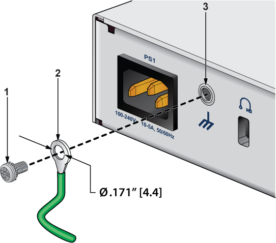
| 1 | Screw M4 (with washer) | 3 | Functional Grounding Point |
| 2 | Solder terminal lug |
This section describes the installation requirements for connecting the power cables to the device.
Installation of this equipment must comply with local and national electrical codes. Consult with the appropriate regulatory agencies and inspection authorities to assure compliance if necessary.
Installation de cet équipement doit être conformes aux codes électriques locaux et nationaux. Si nécessaire, consulter les organismes de réglementation appropriés et des autorités de contrôle pour assurer la conformité.
Read all installation instructions before connecting the system to the power source.
Lire toutes les instructions d'installation avant de brancher le système à la source d'alimentation.
This equipment must be grounded. Never defeat the ground conductor.
Cet équipement doit être mis à la terre. Ne jamais modifier le conducteur de terre.
This unit requires overcurrent protection.
Cet appareil requiert une protection contre les surintensités.
This section describes how to connect the AC power supply to the device.
The AC power supplies are internal to each switch.
Power requirements vary by switch. Refer to the Specifications section for information regarding your specific device.
The Rear Panel section displays the location of the power supplies for a specific device.
Use power supply cables that comply with IEC-320 and have a C13 plug.
This section describes the type of cables required to connect the device.
The following RJ-45 to DB-9 table lists the pin connections of the RJ-45 to DB-9 adapter cable.
| RJ-45 | DB-9 | RJ-45 | DB-9 | ||||
|---|---|---|---|---|---|---|---|
| RTS | 1 | 8 | CTS | GND | 5 | 5 | GND |
| DTR | 2 | 6 | DSR | RXD | 6 | 3 | TXD |
| TXD | 3 | 2 | RXD | DSR | 7 | 4 | DTR |
| GND | 4 | 5 | GND | CTS | 8 | 7 | RTS |
Connect the front panel ports as described below:
Console (Serial) Port: Connect to a computer with the RJ-45 to DB-9 serial adapter cable. The switch uses the following default settings:
Excessive bending can damage interface cables, especially optical cables.
Flexion excessive peut endommager les câbles d'interface, notamment des câbles optiques.