Taiwan RoHS Information
This section provides the Taiwan RoHS information for switches covered by this guide.

www.arista.com
DOC-00136-06
|
Headquarters
5453 Great America Parkway
Santa Clara, CA 95054, USA +1-408 547-5500 www.arista.com
|
Support
+1-408 547-5502
+1-866 476-0000 This email address is being protected from spambots. You need JavaScript enabled to view it.
|
Sales
+1-408 547-5501
+1-866 497-0000 This email address is being protected from spambots. You need JavaScript enabled to view it.
|
This section provides the Taiwan RoHS information for switches covered by this guide.
This section lists the Regulatory Model Numbers (RMNs), where applicable, for the product models for the switches described in this document.
| Regulatory Model Number (RMN) | Product Number(s) |
|---|---|
| AN1620 | DCS-7280CR2A-30
DCS-7280CR2K-30 |
| AN1711 | DCS-7280CR2M-30 |
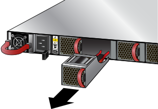
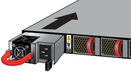
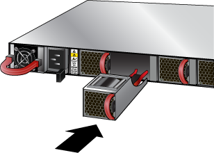
The following steps are required when removing power supplies from a switch.
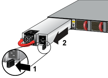
| 1 | Release Lever |
This section displays the front panel of all switches covered by this guide.
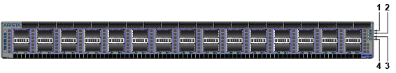
| 1 | System status LED | 3 | Power supply 1 status LED |
| 2 | Fan tray status LED | 4 | Power supply 2 status LED |
All switches covered by this guide use the rear panel shown below. Depending on the power supply module installed, the appearance could be different from the one shown.
.png)
| 1 | Power Supply Module 1 | 4 | Fan Module 2 | 7 | Fan Module 5 |
| 2 | Management Ports | 5 | Fan Module 3 | 8 | Ground |
| 3 | Fan Module 1 | 6 | Fan Module 4 | 9 | Power Supply Module 2 |
This section discusses the following topics:
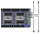
Front panel LEDs are located on the right side of the chassis, as well as the display system, fan, and power supply status.
Figure 1 display the DCS-7280CR2K-30 front panel LEDs.

| 1 | System status LED | 3 | Power supply 1 status LED |
| 2 | Fan tray status LED | 4 | Power supply 2 status LED |
| LED Name | LED State | Device Status |
|---|---|---|
| System Status LED | Blinking Green | System is powering up. |
| Green | Normal operations. Due to power supply and fan redundancy, this LED will remain green if a single fan or power supply is missing or in a failed state. | |
| Blue | The locater function is active. | |
| Amber | Two or more fans (any combination of fan modules or PSU fans) are disconnected or malfunctioning. The switch will automatically execute a “graceful shutdown” shortly. | |
| Fan Status LED | Green | All fan and power modules are operating normally. |
| Amber | Single fan module is removed or malfunctioning. It is also amber when a PSU is completely removed or has a stuck fan rotor. | |
| Red | Two or more fans (any combination of fan modules or PSU fans) are disconnected or malfunctioning. The switch will automatically execute a “graceful shutdown” shortly. | |
| PSU [1:2] Status LED | Green | PSU is functioning and fully operational. AC is present, Aux output is ON, and Main output is ON. |
| Off | PSU has been removed or is not operating properly due to AC cord being unplugged, its fan rotor being stuck, or an internal fault. |
Port LEDs, near their corresponding ports provide a link and operational status. Figure 2 display the Port LED location on the DCS-7280CR2K-30 switch.
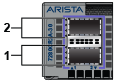
| 1 | Port 1 | 2 | Port 2 |
Table 2 provides status conditions corresponding to port LED states. Port LED behavior for QSFP+ and SFP+ ports is consistent.
| LED State | Status |
|---|---|
| Off | Port link is down. |
|
Green |
Port link is up. |
| Yellow | Port is software disabled. |
| Flashing Yellow | Port failed diagnostics. |
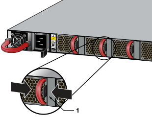
Fan and power supply modules are accessed from the rear panel. Each fan and power supply module contains an LED that reports the module status.
Fan Status LEDs are on the fan modules, as displayed in Figure 3.
Table 3 provides status conditions that correspond to fan status LED states.
The AC Power Supply Status LEDs are on the power supply modules, as displayed in Figure 4.
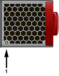
| 1 | Fan Status LED |
| LED State | Status |
|---|---|
| Off | The fan module is not detected. If it is inserted, it may not be seated properly. |
| Green | The fan is operating normally. This LED state is exclusive to its fan module and independent of the states of its neighboring fans and power supplies. |
| Red | The fan has failed. |

| 1 | Handle | 2 | Status LED | 3 | Release |
Table 4 provides status conditions that correspond to the AC power supply status LED states.
| Power Supply State | PWR-1600AC-F |
|---|---|
| Input power present Normal operation | Green |
| Input power present Power Supply fault | Yellow |
| No Input power Supply installed in chassis | Off |
| Input power present Supply not installed in chassis | Green |
Each switch provides an accessory kit containing the parts required to install the switch. This section lists the installation parts contained in the switch accessory kit.
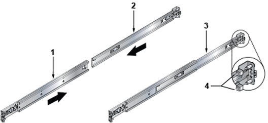
| 1 | Rail Slide | 3 | Assembled Rail |
| 2 | Rail Rod | 4 | Rack Plugs |
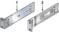
| 1 | Mounting Ear (Left) | 2 | Mounting Ear (Right) |
| Quantity | Description |
|---|---|
| 2 | Power cables: IEC-320/C13-C14, 13 A, 250 V |
| 1 | RJ-45 Patch Panel Cable |
| 1 | RJ-45 to DB9 Adapter Cable |

After mounting the switch into the rack, connect the switch to the data center ground. Figure 1 displays the location of the grounding pads located on the rear panel of the switches.
Grounding wires and grounding lugs (M4 x 0.7) are not supplied. Wire size should meet local and national installation requirements. Commercially available 12 AWG wire is recommended for installations in the U.S.
À la terre et de mise à la terre fils cosses (M4 x 0.7) ne sont pas fournis. Calibre des fils doit satisfaire des exigences de l’installation locale et nationale. Disponible dans le commerce 6 fils AWG est recommandé pour les installations aux États-Unis.
.png)
| 1 | Power Supply Module 1 | 4 | Fan Module 2 | 7 | Fan Module 5 |
| 2 | Management Ports | 5 | Fan Module 3 | 8 | Ground |
| 3 | Fan Module 1 | 6 | Fan Module 4 | 9 | Power Supply Module 2 |
Installation of this equipment must comply with local and national electrical codes. If necessary, consult with the appropriate regulatory agencies and inspection authorities to ensure compliance.
Installation de cet équipement doit être conformes aux codes électriques locaux et nationaux. Si nécessaire, consulter les organismes de réglementation appropriés et des autorités de contrôle pour assurer la conformité.
The switch operates with two installed power supplies. At least one power supply must connect to a power source. Two circuits provide redundancy protection. The Rear Panel displays the location of the power supplies on the rear panel of the switch.
Read all installation instructions before connecting the system to the power source.
Lire toutes les instructions d’installation avant de brancher le système à la source d’alimentation.
This equipment must be grounded. Never defeat the ground conductor.
Cet équipement doit être mis à la terre. Ne jamais modifier le conducteur de terre.
This unit requires overcurrent protection.
Cet appareil requiert une protection contre les surintensités.
The following AC power supplies are supported.
Figure 2 displays an AC power supply, including the power socket on the right side of the module. The AC power supply connects to a circuit that provides the required power, as specified by Table 1.
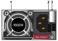
| 1 | Handle | 2 | Status LED | 3 | Release |
The power supplies require power cables that comply with IEC-320. The accessory kit provides two IEC-320 C13 to C14 power cables.
The following DC power supplies are supported.
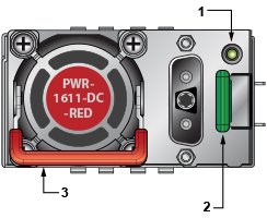
| 1 | Status LED | 2 | Release | 3 | Handle |
A disconnect device must be provided as part of the installation.
Un dispositif de sectionnement doit être fourni dans le cadre de l'installation.
Ensure power is removed from DC circuits before performing any installation actions. Locate the disconnect device, circuit breakers or fuses on DC power lines servicing the circuits. Turn off the power line circuits or remove the fuses.
Pouvoir assurer qu'il est retiré de circuits DC avant d'effectuer des actions d'installation . Localiser les disjoncteurs ou des fusibles sur les lignes de courant continu desservant les circuits. Coupez les circuits de lignes d'alimentation ou retirer les fusibles.
Wire size must comply with local and national requirements and electrical codes. Use only copper wire.
Le calibre du fil doit être conforme aux exigences locales et nationales et les codes électriques. Utiliser du fil de cuivre.
Apply ground connection to the switch first during installation and remove last when removing power.
Appliquer connexion à la terre à l'interrupteur premier lors de l'installation et de supprimer la dernière alimentation lors du débranchement.
The wires connecting the DC power supply to the power source must meet the following requirements:
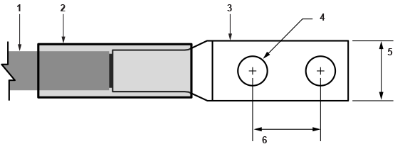
| 1 | Insulated wire | 3 | Lug | 5 | 1/2” |
| 2 | Heat-shrink tubing | 4 | 1/4” | 6 | 5/8” |
Ensure power is removed from DC circuits before performing any installation actions. Locate circuit breakers or fuses on DC power lines servicing the circuits. Turn off the power line circuits or remove the fuses.
Assurez-vous de pouvoir retirer des circuits en courant continu avant d’effectuer toute action d’installation.Localiser les disjoncteurs ou fusibles sur les lignes électriques DC entretien des circuits. Mettez hors tension le circuit ligne ou retirer les fusibles.
Figure 5 displays the exploded and assembled views of the DC power supply with the connection adapter. The adapter is connected to the power supply using two captive fasteners as shown.
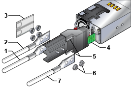
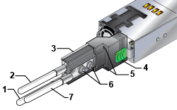
| 1 | -48 V | 4 | Release lever | 7 | Protective earth |
| 2 | Battery return | 5 | Captive screws | ||
| 3 | Terminal cover | 6 | Lug locking nuts |
To connect a DC power supply to power source:
The accessory kit includes the following cables:
Table 1 lists the pin connections of the RJ-45 to DB-9 adapter cable.
| RJ-45 | DB-9 | RJ-45 | DB-9 | |||||
|---|---|---|---|---|---|---|---|---|
| RTS | 1 | 8 | CTS | GND | 5 | 5 | GND | |
| DTR | 2 | 6 | DSR | RXD | 6 | 3 | TXD | |
| TXD | 3 | 2 | RXD | DSR | 7 | 4 | DTR | |
| GND | 4 | 5 | GND | CTS | 8 | 7 | RTS | |
The front panel contains the status LEDs. Figure 6 displays the front panel of the DCS-7280CR2K-30 switch. Figure 7 displays the management ports on the rear panel of the DCS-7280CR2K-30 switch. Front Panel and Rear Panel display the front and rear panels of all switches covered by this guide.
| 1 | System status LED | 3 | Power supply 1 status LED |
| 2 | Fan tray status LED | 4 | Power supply 2 status LED |
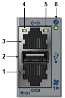
| 1 | Console serial port | 2 | USB port | 3 | Ethernet management port |
| 4 | Link status LED | 5 | Activity status LED | 6 | System status LED |
Connect the management ports as follows:
Excessive bending can damage interface cables, especially optical cables.
Flexion excessive peut endommager les câbles d’interface, notamment des câbles optiques.
When bypassing ZTP, initial switch access requires logging in as admin, with no password, through the console port. Then, you can configure an admin password and other password protected usernames.
This manual configuration procedure cancels ZTP mode, logs into the switch, assigns a password to admin, assigns an IP address to the management port, and defines a default route to a network gateway.