BGP/MPLS L3 VPN
- Maintaining the privacy of each customer.
- Allowing for overlapping IP addresses among customers.
- Having constrained route distribution – only those routers in the Service Provider network that require the customer routes have them.
eos achieves the above through the extensions to BGP as defined in RFC 4364 for IPv4 and RFC 4659 for IPv6, and the use of VPN Routing and Forwarding Tables (VRFs), Route Distinguishers (RDs), and Route Targets (RTs).
Overview
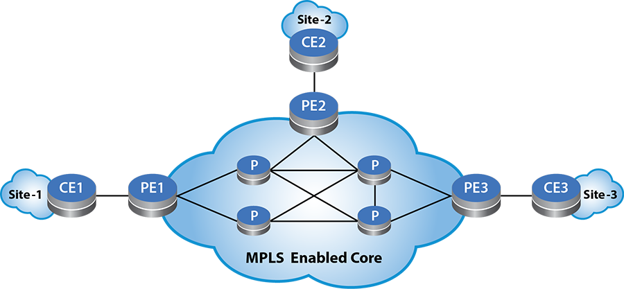
A Virtual Private Network, or VPN, consists of a set of geographically dispersed sites attached to the Service Provider’s (SP) backbone, with IP interconnectivity among the sites. Using this scenario, the customer can obtain “VPN service” from the SP. The SP provides a VPN service to multiple customers, using this common backbone network infrastructure. The sample VPN topology diagram illustrates three sites where a customer interconnects over the SP backbone network.
At each site, the Customer Edge router (CE) attaches to the Provider’s Edge router (PE). The CE can attach to more than one PE, and in these cases, the CE becomes “multi-homed”. The routers in the SP core network, without attachment to any CE, are referred to as “P” routers. The “P” routers do not know about the customer routes.
The CE attaches to PE in a VRF. The routes learned from the CE program in the corresponding VRF and the PE then distributes the routes to other PEs as “VPN routes” using MP-BGP. The switch uses two new BGP address families, VPN-IPv4 (AFI=1, SAFI=128) and VPN-IPv6 (AFI=2, SAFI=128).
On the PEs, corresponding to the VPN, VRFs configure with the RD and one or more import and export RTs. The RD attaches to the customer route to create a VPN route. By picking a unique RD for each VRF and attaching it to the customer route, the VPN route becomes unique. This allows for customers with overlapping IP addresses to be managed by the Service Provider. This unique VPN route advertises to other PEs along with the configured export RT and the VPN label. The PE router allocates a VPN label per VRF and address family. The PE router programs the Label FIB (LFIB) with this label information. When the PE router receives an incoming MPLS packet with the VPN label as the topmost label, it pops the label and performs an IP lookup in the associated VRF. The PE router also maintains a mapping of import RTs to the corresponding VRFs. The switch uses the mapping when deciding into which VRFs to import a received VPN route.
The PE learns customer routes from the CE through the PE-CE routing protocol, which could be Static routing, EBGP, OSPF, or ISIS. The PEinstalls those customer routes in the associated VRF, with the CE as the nexthop. The customer routes in the VRF export into the BGP VPN table as VPN routes, along with the VPN label and the configured export RTs as BGP path attributes. These VPN routes then advertise to other PEs which have been activated for the VPN address-families (VPN-IPv4/VPN-IPv6). The PE then sets itself as the nexthop while advertising the VPN routes. The PE which receives those VPN routes strips out the RD and import them as IPv4 or IPv6 routes into the VRFs. The list of VRFs into which the route is imported is determined based on the mapping of import RTs to VRFs. These routes will be programmed into the FIB along with the VPN label and the remote PE as the nexthop. Once these routes install in the VRF, the CE connected to that VRF learns those routes, based on the PE-CE routing protocol, and make it available it in the attached customer network. This way the geographically dispersed customer sites learn of each other’s networks and IP reachability establishes between the them.
Forwarding
In the Service Provider’s core network, there should be MPLS LSPs between the PEs. The connection to the VPN next-hop should be over an MPLS tunnel. Set up the MPLS LSPs in the core using RSVP-TE or LDP in conjunction with OSPF/ISIS or ISIS-SR.
When the PE receives an IP packet from the CE destined to the remote site, it performs an IP lookup in the VRF to the connected CE. This lookup provides the VPN label to use and the next hop, the remote-PE. The switch imposes the VPN label on the IP packet and the resulting MPLS packet then tunnels through the MPLS LSP to the remote PE. As result of hop popping, the MPLS packet arrives at the remote PE with the VPN label as the topmost label. The label lookup results in popping the VPN label and an IP lookup performed in the associated VRF. Note that the PE would have programmed this label action when it allocated the label. That IP lookup results in the IP packet forwarded out to the CE.
Configuring BGP/MPLS Layer 3 VPN
Configuring BGP/MPLS L3 VPN requires enabling the SP core for MPLS and then configuring the PEs with the required BGP configuration.
The configuration assumes that you have enabled the SP core network for MPLS, by configuring an IGP (OSPF/ISIS) followed by a label distribution protocol such as LDP, RSVP-TE or ISIS-SR. Typically, configure loopback interfaces on all the PE and the P routers and the IGPs exchange reachability to those loopback interfaces. And then the MPLS Label Distribution Protocol sets up MPLS LSPs/tunnels between all the loopbacks.
This section includes the following topics:
- LDP Hello Redundancy
- Enabling BGP to Exchange the Routing Tables with the Peer
- Configuring the VRF Information
- Configuring the Route Distinguisher
- Configuring Route Targets
- Configuring Import / Export Route-maps
- VPN Next-hop
Use the following steps to enable MPLS and LDP on the PE:
Configure the terminal.
switch# configure terminalEnter the Loopback0 Interface configuration Mode.
switch(config)# interface Loopback0Configure the destination IP address.
switch(config)# ip address 11.0.0.1/32Enable MPLS routing.
switch(config)# mpls ipConfigure MPLS LDP.
switch(config)# mpls ldpConfigure the router ID interface.
switch(config-mpls-ldp)# router-id interface Loopback0Configure no shutdown.
switch# configure terminal
switch(config)# interface Loopback0
switch(config-if)# ip address 11.0.0.1/32
switch(config)# mpls ip
switch(config)# mpls ldp
switch(config-mpls-ldp)# router-id interface Loopback0
switch(config-mpls-ldp)# no shutdown
LDP Hello Redundancy
- Devices must have a loopback interface configured to serve as the transport address interface, which must be routable through all interfaces on the device.
- Devices must be reachable via a redundant path through other devices on the network.
- Both devices must have Hello Redundancy configured or the targeted Hello messages will be ignored.
After establishing a Hello adjacency using LDP Basic Discovery, devices with Hello Redundancy start sending Targeted Hello messages to the Transport Address found in the received Link Hello message of Basic Discovery. The Targeted Hello adjacency can support the session established between peers even when all Link Hello adjacencies have timed out. The FEC label bindings between two peers with no Link Hello adjacency do not become active because the Interior Gateway Protocol does not use the other peer as the next hop. Maintaining the FEC label bindings and the session between the two peers can save significant time when re-establishing the Link Hello adjacency.
The neighbor hello-redundancy command configures Hello Redundancy on all platforms under the LDP configuration mode. If a Link Hello adjacency restores within 600 seconds of getting lost, the switch drops the Target Hello adjacency and the session associated with it. The timeout can be configured using the duration option of the command. An infinite value for the duration disables the timeout.
configuration for LDP Hello Redundancy
The following example applies to all platforms.
These commands enable Targeted Hello redundancy with a duration of 300 seconds.
switch(config-mpls-ldp)# neighbor hello-redundancy
switch(config-mpls-ldp)# neighbor hello-redundancy duration 300
Use either of the following commands to disable Hello Redundancy.
switch(config-mpls-ldp)# neighbor hello-redundancy none
switch(config-mpls-ldp)# default neighbor hello-redundancy
The following command shows the Targeted Hello adjacencies established.
switch(config)# show mpls ldp discovery detail
LDP MD5 Password Not Set
Local LDP Identifier: 2.2.2.2:0
Discovery Sources:
   Interfaces:
      Ethernet1 (ldp):
         Hello interval: 5 sec; Source IP addr: 192.168.2.1
         LDP ID: 3.3.3.3:0
            Source IP addr: 192.168.2.2; Transport IP addr: 3.3.3.3
            Hold time: 15 sec; Proposed local/peer: 15/15 sec; Expires in: 11.96 sec
      Ethernet2 (ldp):
         Hello interval: 5 sec; Source IP addr: 192.168.1.2
         LDP ID: 1.1.1.1:0
            Source IP addr: 192.168.1.1; Transport IP addr: 1.1.1.1
            Hold time: 15 sec; Proposed local/peer: 15/15 sec; Expires in: 12.00 sec
   Targeted Hellos:
      Targeted neighbor 1.1.1.1:
         Hello interval: 15 sec; Source IP addr: 2.2.2.2
         LDP ID: 1.1.1.1:0
            Source IP addr: 1.1.1.1; Transport IP addr: 1.1.1.1
            Hold time: 45 sec; Proposed local/peer: 45/45 sec; Expires in: 40.78 sec
            Target configuration source: Hello Redundancy
      Targeted neighbor 3.3.3.3:
         Hello interval: 15 sec; Source IP addr: 2.2.2.2
         LDP ID: 3.3.3.3:0
            Source IP addr: 3.3.3.3; Transport IP addr: 3.3.3.3
            Hold time: 45 sec; Proposed local/peer: 45/45 sec; Expires in: 35.89 sec
            Target configuration source: Hello Redundancy
Enabling BGP to Exchange the Routing Tables with the Peer
- Activating the peer, the remote PE, under the address-family VPN-IPv4 and address-family VPN-IPv6 modes enables BGP to negotiate the MPLS L3 VPN address families.
- Specify the address for the VPN next-hop using the command, neighbor default encapsulation mpls next-hop-self source-interface Loopback0.
In the preceding configuration example, the system uses the address 11.0.0.1 from interface Loopback0 as the nexthop in the VPN route advertisements.
Configuring the VRF Information
First, the VRF must be configured in the global mode and IPv4 and IPv6 routing must be enabled in the VRF. After that, under the router bgp mode, configure the VRF and provide the information related to RD and import and export RTs.
Configure terminal.
switch# configure terminalEnable IP routing.
switch(config)# ip routingEnable IP routing for the VRF.
switch(config)# ip routing vrf vrf1Enable IPv6 routing for the VRF.
switch(config)# ipv6 unicast-routing vrf vrf1switch# configure terminal
switch(config)# ip routing
switch(config)# ip routing vrf vrf1
switch(config)# ipv6 unicast-routing vrf vrf1Display the VRF configuration information under router BGP mode.
switch(config-router-bgp-vrf-vrf1)# show active
router bgp 300
  vrf vrf1
    rd 11.0.0.1:0
    route-target import vpn-ipv6 300:0
    route-target import vpn-ipv4 300:0
    route-target import vpn-ipv4 300:0
    route-target import vpn-ipv4 300:0
    route-target export vpn-ipv6 300:0
    route-target export vpn-ipv4 300:0
    redistribute connected
    redistribute static
switch(config-router-bgp-vrf-vrf1)#
Configuring the Route Distinguisher
The Route Distinguisher (RD) has s structure that can easily be configured and managed. Configure it by specifying two fields separated by a colon, as in administrative-subfield: assigned-number-subfield.
The administrative subfield contains either an IP address such as the PEs loopback address or the AS number. The assigned-number-subfield can be any number determined by the SP. The RD must be unique per VRF. You can have overlapping address space between VRFs, but the RD ensures that a VPN route can be uniquely identified as received by a remote PE. However, the identification of which VRF(s) to import the received VPN route should be handled by the import routing tables configured on the remote PE.
Configuring Route Targets
- Received VPN routes with the import RT as path attributes import into the VRF and have RTs with extended-community BGP path attributes. They import into VRFs which import RT configuration for RTs in the received VPN route.
- And while advertising the routes from the VRF as VPN routes, the export RT
attaches to the route as an extended-community BGP attribute.
- In the example, the connected and static routes in the VRF redistribute into BGP. And these routes export as VPN routes.
- You can also have a BGP session with the CE. In that case, routes received over that session export as VPN routes. And imported routes advertise to the CE.
Configuring Import and Export Route Maps
BGP only considers the route targets referenced in the route-target import statement for route import. However, the routes imported into a VRF can be further controlled by applying an import route-map. And the routes exported from the VRF can be controlled by applying an export route-map. Note that the import route-map does not allow importing additional route targets. Instead, it allows more granular control of the imported routes. The same concept applies to the export route-map, and the export route-map allows more granular control of the exported routes.
Complete the following steps:
Configure the terminal.
switch# configure terminalConfigure BGP,4274781899.
switch(config)# router bgp 4274781899Configure the VRF under Router BGP configuration Mode.
switch(config-router-bgp)# vrf vrf1Select the BGP route distinguisher, 36351:268450419.
switch(config-router-bgp-vrf-vrf1)# rd 36351:268450419Configure the import route-target VPN-IPv4, unicast address family, 36351:1001.
switch(config-router-bgp-vrf-vrf1)# route-target import vpn-ipv4 36351:1001Optionally, configure a second import route-target for VPN-IPv4 unicast address family, 36351:268450419.
switch(config-router-bgp-vrf-vrf1)# route-target import vpn-ipv4 36351:268450419Configure the export route-target for VPN-IPv4 unicast address family, 36351:1001.
switch(config-router-bgp-vrf-vrf1)# route-target export vpn-ipv4 36351:1001Configure the import route-map, BGP-IMPORT-VRF-SERVICES.
switch(config-router-bgp-vrf-vrf1)# route-target import vpn-ipv4 route-map BGP-IMPORT-VRF-SERVICESConfigure the export route-map, BGP-EXPORT-VRF-VRF1.
switch(config-router-bgp-vrf-vrf1)# route-target export vpn-ipv4 route-map BGP-EXPORT-VRF-VRF1Optionally, redistribute connected routes in the VRF into BGP, with the associated route-map BGP-ANNOUNCE-CONNECTED.
switch(config-router-bgp-vrf-vrf1)# redistribute connected route-map BGP-ANNOUNCE-CONNECTEDOptionally, redistribute static routes in the VRF into BGP, with the associated route-map BGP-ANNOUNCE-STATIC.
switch(config-router-bgp-vrf-vrf1)# redistribute static route-map BGP-ANNOUNCE-STATICThe import and export route-maps should be configured separately . The configuration example displays the configuration of the same route-map BGP-IMPORT-VRF-SERVICES.
switch(config-router-bgp-vrf-vrf1)# route-map BGP-IMPORT-VRF-SERVICES permit 10
switch(config-route-map-BGP-IMPORT-VRF-SERVICES)# match extcommunity SERVICES
switch(config-route-map-BGP-IMPORT-VRF-SERVICES)# match ip address prefix-list SERVICESswitch# configure terminal
switch(config)# router bgp 4274781899
switch(config-router-bgp)# vrf vrf1
switch(config-router-bgp-vrf-vrf1)# rd 36351:268450419
switch(config-router-bgp-vrf-vrf1)# route-target import vpn-ipv4 36351:1001
switch(config-router-bgp-vrf-vrf1)# route-target import vpn-ipv4 36351:268450419
switch(config-router-bgp-vrf-vrf1)# route-target export vpn-ipv4 36351:1001
switch(config-router-bgp-vrf-vrf1)# route-target import vpn-ipv4 route-map BGP-IMPORT-VRF-SERVICES
switch(config-router-bgp-vrf-vrf1)# route-target export vpn-ipv4 route-map BGP-EXPORT-VRF-VRF1
switch(config-router-bgp-vrf-vrf1)# redistribute connected route-map BGP-ANNOUNCE-CONNECTED
switch(config-router-bgp-vrf-vrf1)# redistribute static route-map BGP-ANNOUNCE-STATIC
switch(config-router-bgp-vrf-vrf1)# route-map BGP-IMPORT-VRF-SERVICES permit 10
switch(config-route-map-BGP-IMPORT-VRF-SERVICES)# match extcommunity SERVICES
switch(config-route-map-BGP-IMPORT-VRF-SERVICES)# match ip address prefix-list SERVICESConfiguring VPN Next Hop
By default, the system uses the source address of the BGP session as the next hop in the VPN advertisements. The switch determines the source address while establishing the TCP session between the PEs. If the SP uses a different address as the VPN next-hop, then an interface with that address must be specified under the BGP address-family VPN-IPv4 or address-family VPN-IPv6 configuration modes.
switch(config-router-bgp)# address-family vpn-ipv4
switch(config-router-bgp-af)# neighbor 10.0.0.2 activate
switch(config-router-bgp-af)# neighbor default encapsulation mpls next-hop-self source-interface Loopback0


switch(config-router-bgp)# address-family vpn-ipv6
switch(config-router-bgp-af)# neighbor 10.0.0.2 activate
switch(config-router-bgp-af)# neighbor default encapsulation mpls next-hop-self source-interface Loopback0
Specify the interface Loopback 0 and then the switch selects the VPN next-hop address from the interface based on the following rules:
- For VPN-IPv4, the switch selects the IPv4 address from the interface.
- For VPN-IPv6, if the interface does not have a IPv4 address, select the IPv6 address.
- For an IPv6 peer, select the IPv6 address from the interface. If the interface does not have an IPv6 address, select the IPv4 address.
For VPN-IPv6, if an IPv4 address selected as the next-hop, eos encodes it as a IPv4-mapped IPv6 address in the VPN route advertisement.
LDP Pseudowire Show Commands
Use the show patch panel command to display the overall status of the configured pseudowire patches.
switch# show patch panel
Patch     Connector                            Status
--------- ------------------------------------ ----------
example   1: Ethernet3                         Up
          2: Port-Channel2
example2  1: Ethernet1 802.1Q VLAN 100         Up
          2: LDP neighbor 1.1.1.1 PW ID 1111
example3  1: LDP neighbor 4.4.4.4 PW ID 1040   Up
          2: Ethernet2
Use the show patch panel detail command to display the detailed status of the configured pseudowire patches.
switch# show patch panel detail
PW Fault Legend:
   ET-IN - Ethernet receive fault
   ET-OUT - Ethernet transmit fault
   TUN-IN - Tunnel receive fault
   TUN-OUT - Tunnel transmit fault
   NF - Pseudowire not forwarding (other reason)
Patch: example, Status: Up
   Connector 1: Ethernet3
      Status: Up
   Connector 2: Port-Channel2
      Status: Up
Patch: example2, Status: Up
   Connector 1: Ethernet1 802.1Q VLAN 100
      Status: Up
   Connector 2: LDP neighbor 1.1.1.1 PW ID 1111
      Status: Up
      Local MPLS label: 100032, Group ID: 0
         MTU: 9000, 802.1Q VLAN request sent: -
      Neighbor MPLS label: 900000, Group ID: 0x0
         MTU: 9000, 802.1Q VLAN request received: -
      PW type: 4 (tagged), Control word: N
      Tunnel type: LDP, Tunnel index: 198
Patch: example3, Status: Up
   Connector 1: LDP neighbor 4.4.4.4 PW ID 1040
      Status: Up
      Local MPLS label: 100002, Group ID: 0x0
         MTU: 1500, 802.1Q VLAN request sent: -
      Neighbor MPLS label: 400000, Group ID: 0x0
         MTU: 9213, 802.1Q VLAN request received: -
      PW type: 5 (raw), Control word: N
      Tunnel type: LDP, Tunnel index: 2
   Connector 2: Ethernet2
      Status: Up
Use the show patch panel forwarding command to display the forwarding information for configured pseudowire connectors.
switch# show patch panel forwarding
Legend:
   Type - Pseudowire type: 4 (tagged)
                           5 (raw)
   CW - Control word used

In/Out                       Type CW VLAN Status Patch
---------------------------- ---- -- ---- ------ ------------
Et1 802.1Q VLAN 100             4         Up     example2
   Label 900000, LDP Tun 198
Et2                             5         Up     example3
   Label 400000, LDP Tun 2
Et3                                       Up     example
   Po2
Po2                                       Up     example
   Et3

PW Label Out                   Source Type CW Status Patch
-------- --------------------- ------ ---- -- ------ ----------
100002   Et2                   LDP       5    Up     example3
100032   Et1 802.1Q VLAN 100   LDP       4    Up     example2
Limitations
- While configuring a BGP Route-Reflector for the VPN-IPv4/VPN-IPv6 address families, the route-reflector must have transport MPLS LSPs to reach the PE nexthop addresses. Even though the route-reflector may not be in the data path and does not use the transport LSPs to forward traffic, the LSPs are required in order for the BGP nexthops to be considered as reachable valid candidates in the bestpath computation.
- When configuring eBGP peers, which receive routes over an eBGP session and re-advertise the same to a different eBGP peer, next-hop-unchanged knob must be configured, so that the original nexthop is retained.
- With iBGP route-reflector topology, next-hop-self knob must not be configured.
- Even with directly connected PEs, the VPN
nexthops should be the loopback on the directly
connected PEs with an MPLS tunnel between them.
- For a VPN route to be installed in the VRF, the VPN nexthop must resolve over a MPLS tunnel.
- With OSPF as the PE-CE protocol, RFC 4576, setting of the DN bit in the LSA, is not supported.
- Internal BGP (iBGP) as the PE-CE protocol, RFC 6368, is not supported.