IS-IS
Intermediate System-to-Intermediate System (IS-IS) intra-domain routing information exchange protocol is designed by the International Organization for Standardization to support connectionless networking. This protocol is a dynamic routing protocol.
IS-IS introduction
IS-IS is a link-state protocol, which uses the Shortest Path First (SPF) algorithm. IS-IS and the OSPF protocol are similar in many aspects. As an Interior Gateway Protocol (IGP), IS-IS runs inside an Autonomous System (AS).
To enable IS-IS, you must instantiate an IS-IS routing instance and assign it to an interface. Arista IS-IS support includes IS-IS segment routing and IS-IS graceful restart.
IS-IS Segment Routing
Segment Routing (SR) provides a mechanism to simplify the definition of end-to-end paths within IGP topologies by encoding paths as sequences of topological sub-paths, called segments. The IS-IS protocol advertises these segments in four different ways: node segments, prefix segments, proxy-node segments, and adjacency segments.
- Node-SID - Represents a node in an IGP topology. Uses an index or label associated with an Ipv4 or IPv6 address on a loopback interface of a router.
- Proxy Node-SID - Associated with an IP(v6) address received from a router that does not support IS-IS SR.
- Prefix-SID - Represents an ECMP-aware shortest path to a prefix (or a node), as per the state of the IGP topology.
- Adjacency Segments - Represents a hop over a specific adjacency between two nodes in IGP.
TI-LFA FRR using IS-IS Segment-Routing
Topology Independent Fast Reroute, or TI-LFA, uses IS-IS SR to build loop-free alternate paths along the post-convergence path. These loop-free alternates provide fast convergence in the range of sub-50 ms.
The (Point of Local Repair (PLR)- the router where TI-LFA is configured) PLR switches to these loop-free alternate backup paths in the event of a link down (link-protection) or BFD neighbor down (node-protection) event, protecting traffic destined to IS-IS SR node segments, adjacency segments, and anycast segments while the IGP converges and the post-convergence paths are computed. Anycast segment protection is restricted to those segments which are attached to prefixes with host mask (/32 for V4 address and /128 for v6 address).
- eos Release 4.22.1F adds support for TI-LFA backup paths that protect IS-IS SR labeled traffic corresponding to a node segment or adjacency segment on a transit router.
- eos Release 4.23.1F adds support for TI-LFA backup paths that protect IS-IS SR tunnels.
- eos Release 4.24.1 adds support for protecting IS-IS SR labeled traffic corresponding to anycast segments.
- eos Release 4.24.2F adds support for calculating TI-LFA backup paths that exclude the SRLG configured on the failing link.
Backup paths are only installed for IS-IS SR labeled routes and tunnels corresponding to node segments, adjacency segments, and anycast segments. When requesting node-protection, and no node-protecting LFAs are available, a link-protecting LFA is computed instead. TI-LFA FRR using IS-IS Segment-Routing is available with the multi-agent routing protocol model and the ribd routing protocol model.
Other traffic that resolves over IS-IS SR tunnels, such as LDP pseudowires, BGP LU tunnels, BGP IP routes, L2 EVPN, MPLS L3 VPN, and so on, are also protected by the TI-LFA tunnel that protects the resolving IS-IS SR tunnel.
TI-LFA FRR using IS-IS Segment-Routing Configuration
The following configuration tasks can be performed by Topology Independent Fast Reroute (TI-LFA FRR) using IS-IS Segment-Routing.
TI-LFA FRR using IS-IS SR Commands
Limitations
- Backup paths are not computed for prefix segments that do not have a host mask (/32 for v4 and /128 for v6).
- When TI-LFA is configured, the number of anycast segments generated by a node cannot exceed 10.
- Computing TI-LFA backup paths for proxy node segments is not supported.
- Backup paths are not computed for node segments corresponding to multi-homed prefixes. The multi-homing could be the result of them being anycast node segments, loopback interfaces on different routers advertising SIDs for the same prefix, node segments leaked between levels, and thus being seen as originated from multiple L1-L2 routers.
- Backup paths are only computed for segments that are non-ECMP.
- Only IS-IS interfaces that are using the point-to-point network type are eligible for protection.
- Link/node protection is only supported in the default VRF owing to the lack of non-default VRF support for IS-IS segment-routing.
- Backup paths are computed in the same IS-IS level topology as the primary path.
- Even with IS-IS GR configured, SSU, SSO, agent restart are not hitless events for IS-IS SR LFIB routes or tunnels being protected by backup paths.
IS-IS Graceful Restart
IS-IS Graceful Restart (GR) provides a mechanism to prevent routing protocol re-convergence during a processor switchover or device downtime. Normally, when a router restarts, all the neighboring routers associated with that router detect that the device went down and remove routes from that neighbor. When the router restarts, the session re-establishes, and data transfer continues. During the restart, the removal and re-insertion of routes cause data loss. Prevent data loss by configuring Graceful Restart on the device.
- Smart Software Upgrade (SSU).
- A planned Stateful SwitchOver (SSO) for maintenance reasons or an unplanned SSO due to failures on the active supervisor.
- RIB agent restart due to software failures.
With IS-IS Graceful Restart (GR) configured, a redundancy switchover from an active to a standby supervisor, or SSU, or restart of the IS-IS software, the RIB agent, should be a hitless event if the GR completes successfully. Neighboring routers continue to forward traffic to the restarting router, and traffic forwarding through the restarting router continues without loss. When GR successfully completes, the failure of a router should be completely transparent to network applications.
- IS-IS GR with unplanned software restart supported on all platforms.
- IS-IS GR with SSO supported on modular dual-supervisor platforms.
- IS-IS GR with SSU supported on platforms that support SSU.
IS-IS Dynamic Flooding
Dynamic Flooding allows IS-IS to scale to large, dense topologies such as Leaf-Spine topologies. In such topologies, legacy IS-IS can exhibit a congestive collapse due to the control plane load created by excessively redundant flooding.
The concept in Dynamic Flooding is to dynamically compute a restricted topology for flooding (the flooding topology). Since this can be much smaller than the full physical topology, this can reduce the redundancy seen by each node, thereby reducing the control plane load and avoiding a congestive collapse.
To do this, first select one node within the IS-IS area as the area leader. Leverage the Designated Intermediate System (DIS) election algorithm for this, except instead of applying it to the neighbors on an interface, compute it across all of the nodes within the area.
The area leader is responsible for computing the flooding topology. This is distributed to the other nodes in the area through the Area System IDs TLV and the Flooding Path TLV.
All nodes within the area then flood only on the flooding topology.
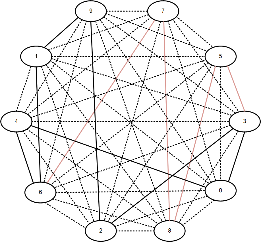
A flooding topology on a dense graph. The flooding topology is shown by the solid lines. Dotted lines indicate non-flooding links.
In a dense topology, this can reduce the amount of flooding by an order of magnitude or more, with a resulting increase in scalability.
Dynamic Link Delay using TWAMP Light
Overview of Link Delay using Two-Way Active Measurement Protocol (TWAMP)
eos provides TWAMP support as a protocol used for active network performance monitoring. It measures the end-to-end performance of a network path by sending and receiving packets between two network devices. Previously, you could statically configure the minimum and maximum link delay, but with the addition of TWAMP, eos supports dynamic measurement of link delay as described in RFC8186 and provides it to the IS-IS FlexAlgo dynamically.
- Active - The device initiates sending probe packets and receives reflected packets with a timestamp to compute link-delay.
- Reflector - The device receives the probe packet, adds the timestamps, and sends it back.
The two modes operate independently, and the same interface can be in Active mode and Reflector mode simultaneously. To avoid conflict, configure different UDP ports for each mode.
IS-IS advertises the unidirectional link delay (the average delay), unidirectional min-max delay, and unidirectional delay variation measured by TWAMP Light. Only the unidirectional min-max delay advertises in Application Specific Link Attributes Sub-TLV (ASLA).
This feature only supports IPv4 probe packets, but eos utilizes the measured link-delay values for IPv4 and IPv6 topologies in IS-IS multi-topology deployments.
Platform Support
eos supports this feature on the following platforms:
- 7500R3X
- 7800R3X
- DCS-7280XR3X
The platforms must have at least one Femtocell Access Point (FAP) with the Revision of Q2c2TX. To verify the FAP revision, use the following command:
switch#show platform fap
Switches currently in the system

Name       Type           Device          Revision
---------- -------------- --------------- --------------
Fap0       Jericho2       Jericho2c       Q2c2tA1
IS-IS Configuration
- Enabling IS-IS
- Configuring IS-IS Optional Global Parameters
- Configuring Optional IS-IS Interface Parameters
- Configuring IS-IS Segment Routing
- Configuring Redistribution of DHCP for IS-IS Agent (IPv6)
- Disabling IS-IS
- Configuring IS-IS Graceful Restart (GR)
- IS-IS Advertisement and Reachability of Interface Addresses
- Configuring Dynamic IS-IS Link Delay using TWAMP
- TI-LFA FRR using IS-IS Segment-Routing Configuration
- IS-IS Dynamic Flooding Configuration
- Relax Address-Family Check for IS-IS Adjacency
- Configuring Dynamic IS-IS Link Delay using TWAMP
- Displaying IS-IS Information
Enabling IS-IS
Enabling IS-IS Globally and Specifying an IS-IS Instance
The switch supports only one IS-IS routing instance per VRF. The routing instance uniquely identifies the switch to other devices. IS-IS configuration commands apply globally to the IS-IS instance.
The switch must be in router IS-IS configuration mode to run IS-IS configuration commands. The router isis command places the switch in router IS-IS configuration mode.
Example
switch(config)# router isis Osiris
switch(config-router-isis)#
Configuring the Network Entity Title (NET)
After creating an IS-IS routing instance, configure the Network Entity Title (NET) with the net command. The NET defines the IS-IS area address and the system ID of the device.
Example
switch(config)# router isis Osiris
switch(config-router-isis)# net 49.0001.1010.1040.1030.00
Setting the Address Family Configuration
The address-family command enables the address families that IS-IS will route and places the switch in the configuration mode for that address family. The address families supported are IPv4 unicast and IPv6 unicast.
Example
switch(config)# router isis Osiris
switch(config-router-isis)# address-family ipv4 unicast
switch(config-router-isis-af)#
Enabling IS-IS on a Specified Interface
After enabling IS-IS globally, enable it on an interface with the isis enable command.
Example
switch(config-router-isis)# interface ethernet 4
switch(config-if-Eth4)#isis enable Osiris
Configuring IS-IS Optional Global Parameters
- Setting the Router Type
- Configuring Redistribution of Connected or Static Non-ISIS Routes
- Configuring Redistribution of Connected or Static non-ISIS Routes into Level-1 or Level-2
- Configuring Redistribution of BGP Routes into ISIS
- Setting the Overload Bit
- Configuring IS-IS MD5 Authentication
- Setting the SPF Interval
- Configuring IS-IS Segment Routing Global Adjacency-SID
- Enabling Logging for Peer Changes
- Setting the IS-IS hostname
- Configuring IS-IS Multi-Topology
Setting the Router Type
The is-type command sets the routing level for an IS-IS instance.
Example
switch(config)# router isis Osiris
switch(config-router-isis)# is-type level-2
switch(config-router-isis)#
Configuring Redistribution of Connected or Static Non-ISIS Routes
The redistribute (IS-IS) command configures redistribution of connected or static non-ISIS routes.
Example
switch(config)# router isis Osiris
switch(config-router-isis)# redistribute connected
switch(config-router-isis)#
Configuring Redistribution of Connected or Static Non-ISIS Routes into Level-1 or Level-2
Non-ISIS routes can be exported into Level-1, Level-2, or both using a route map. By default, the routes are exported only to Level-2; to export to Level-1 or to both levels, configure the route map using the set isis level command. The Level-1 or Level-2 routes can also be filtered using the route maps match statement. The route map is then used when redistributing routes in ISIS with the redistribute (IS-IS) command.
Use the show isis database detail command to make sure that the route shows up in the exported level.
- The following commands configure a route map called
rm to set the IS-IS level to Level-1, then
use it to redistribute connected routes.
switch(config)# route-map rm switch(config-route-map-rm)# set isis level level-1 switch(config-route-map-rm)# router isis osiris switch(config-router-isis)# redistribute connected route-map rm switch(config-router-isis)# - The following command displays IS-IS database information and confirms that
the level has been set to Level-1.
switch# show isis database detail
ISIS Instance: inst1 VRF: default
 ISIS Level 1 Link State Database
 LSPID Seq Num Cksum Life IS Flags
 1111.1111.1001.00-00 10 63306 751 L2 <>
 NLPID: 0xCC(IPv4) 0x8E(IPv6)
 Area address: 49.0001
<-------OUTPUT OMITTED FROM EXAMPLE-------->
Configuring Redistribution of BGP Routes into ISIS
The redistribute bgp route-map command redistributes the BGP routes from the specified route map into IS-IS. Only one route map can be specified; reissuing the command overrides any previous configuration.
The no redistribute bgp and default redistribute bgp commands disable BGP route redistribution from the specified domain by removing the redistribute bgp statement from running-config.
The command is available in both router IS-IS configuration mode and the address-family submode. The command is rejected if configured in both modes at the same time. Issuing the no or default command in router IS-IS configuration mode has no effect on redistribution configured in the address-family submode.
- These commands redistribute IPv4 BGP routes from the route map called
bgp-to-isis-v4 into the ISIS
domain.
switch(config)# router isis 1 switch(config-router-isis)# address-family ipv4 switch(config-router-isis-af)# redistribute bgp route-map bgp-to-isis-v4 switch(config-router-isis-af)# - These commands redistribute all BGP routes from the route map
bgp-to-isis into
ISIS.
switch(config)# router isis 1
switch(config-router-isis)# redistribute bgp route-map bgp-to-isis
Setting the Overload Bit
The overload bit is set in link state packets (LSPs) to signal that the switch is not available for forwarding transit traffic (for instance, during startup or when the switch is being taken down for maintenance). To set the overload bit manually, use the set-overload-bit command without the on-startup option. To configure the switch to set the overload bit after a reboot, allowing routing protocols to converge before the switch is used for forwarding traffic, use the set-overload-bit command with the on-startup option. The overload bit will remain set for the interval specified after startup.
In scenarios when Border Gateway Protocol (BGP) routes are resolved using an Interior Gateway Protocol (IGP), if the transit router reboots and becomes available again, the IGP will consider the transit router as an optimal path again. After rebooting, the transit router will blackhole traffic until the transit router learns the external destination reachability information via BGP.
-
These commands configure the switch to set the overload bit in LSPs sent for 120 seconds after startup.
switch(config)# router isis Osiris switch(config-router-isis)# set-overload-bit on-startup 120 switch(config-router-isis)# - These commands configure the overload bit until BGP converges.
If BGP fails to converge within the set timeout default
period, then the overload bit gets
cleared.
switch(config)# router isis Osiris
switch(config-router-isis)# set-overload-bit on-startup wait-for-bgp
switch(config-router-isis)# set-overload-bit on-startup wait-for-bgp timeout 750
switch(config-router-isis)#
Configuring IS-IS MD5 Authentication
To configure authentication for the IS-IS instance causing LSPs, CSNPs, and PSNPs to be authenticated, use the authentication mode and authentication key commands. To configure authentication on the interface, causing IS-IS Hellos to be authenticated, use the isis authentication mode and isis authentication key commands on the interface.
Two forms of authentication are supported by the IS-IS routing protocol: Clear-text authentication and MD5 authentication. The difference between the two forms of authentication is in the level of security provided. In the case of clear-text authentication, the password is specified as text in the authentication TLV, making it possible for an attacker to break authentication by sniffing and capturing IS-IS PDUs on the network. Arista recommends using the MD5 authentication.
HMAC MD5 authentication provides much stronger authentication by computing the message digest (on the IS-IS PDU contents) using the secret key to produce a hashed message authentication code (HMAC). Different modes of authentication can be specified on the interface, which authenticates IIH PDUs (IS-IS hello PDUs), and globally in the router IS-IS mode, in which the LSPs, CSNPs and PSNPs are authenticated. Area-wide and domain-wide authentication can be specified for L1 and L2 routers respectively.
- These commands configure authentication for the IS-IS instance causing LSPs,
CSNPs, and PSNPs to be
authenticated.
switch(config)# router isis 1 switch(config-router-isis)# authentication mode md5 switch(config-router-isis)# authentication key secret switch(config-router-isis)# - These commands configure authentication on the interface causing IS-IS hellos to
be
authenticated.
switch(config)# interface Ethernet 3/6
switch(config-if-Et3/6)# isis authentication mode text
switch(config-if-Et3/6)# isis authentication key 7 cAm28+9a/xPi04o7hjd8Jw==
switch(config-if-Et3/6)#
To maximize interoperability, Arista recommends using the same key in both interface mode and in the router isis mode.
Setting the SPF Interval
- Maximum wait interval: The maximum time a switch will wait before running an SPF after a topology change.
- Initial wait interval: In a network that has been stable throughout the hold interval, this interval defines the initial wait time of a switch for performing an SPF calculation after a topology change. As several link-state updates must be sent after a topology change, the initial wait interval allows the network to settle before a switch computes an SPF. If the topology changes during an initial wait interval, an SPF is calculated after the initial wait interval expires and no further changes are made to throttle timers.
- Hold time: This interval delays SPF calculations during
network instability. If the topology changes during a hold
time, an SPF is computed when the hold time expires.
Subsequent hold intervals are doubled up to the configured
maximum wait interval for continuous topology changes. If
the next topology change occurs after the hold interval
expires, the hold interval is reset to its configured value
and the SPF is computed after the initial wait
interval.Note: eos does not support configuring topology-specific SPF timers in multi-topology deployments and IS-IS level-specific SPF timers.
Example
This command configures maximum wait interval, initial wait interval, and hold time to 10 seconds, 2000 ms, and 1000 ms respectively.
switch(config)# router isis inst1
switch(config-router-isis)# spf-interval 10 2000 1000
Configuring IS-IS Segment Routing Global Adjacency-SID
IS-IS Segment Routing (SR) supports global adjacency SIDs for point-to-point interfaces. The adjacency SID is configured as an index using the adjacency-segment command.
Global adjacency segments are represented using an index instead of actual MPLS labels. The index is an offset into the Segment Routing Global Block (SRGB) advertised by a router, resulting in an MPLS label. The default value of SRGB in eos is Base: 900000 and Size: 65536.
The same index may be used to configure multiple interfaces so that MPLS forms an ECMP group, and the same index may be applied to IPv4 and IPv6 adjacencies.
Example
switch(config-if-Et1)# adjacency-segment ipv4 p2p index 10 globalDisplaying Adjacency SID Information
The command show isis segment-routing adjacency-segments displays the global adjacency SID value and other related information.
- In this example an interface is configured as follows:
interface ethernet1 ip address 1.1.1.1/24 ipv6 address 1000::1/64 isis enable isis1 isis network point-to-point adjacency-segment ipv4 p2p index 1 global adjacency-segment ipv6 p2p index 2 global - The show output for the above interface
configuration:
switch# show isis segment-routing adjacency-segments

System ID: 1000.0000.0002                       Instance: isis1
SR supported Data-plane: MPLS                   SR Router ID: 1.1.1.4
Adj-SID allocation mode: SR-adjacencies
Adj-SID allocation pool: Base: 100000     Size: 16384
Adjacency Segment Count: 2
Flag Descriptions: F: Ipv6 address family, B: Backup, V: Value
                  L: Local, S: Set

Segment Status codes: L1 - Level-1 adjacency, L2 - Level-2 adjacency, P2P -
Point-to-Point adjacency, LAN - Broadcast adjacency

Locally Originated Adjacency Segments
Adj IP Address     Local Intf  SID     SID Source   Flags                 Type
-----------------  ----------  ------  -----------  ---------------       -------
1.1.1.2            Et1         1       Configured    F:0 B:0 V:0 L:0 S:0  P2P L1
fe80::1:ff:fe65:0  Et1         2       Configured    F:1 B:0 V:0 L:0 S:0  P2P L1


Received Global  Adjacency Segments
SID              Originator             Neighbor          Flags
---------        --------------------   ----------------  ---------
    0                 rtrmpls1          1000.0000.0002     F:0 B:0 V:0 L:0 S:0
Enabling Logging for Peer Changes
The log-adjacency-changes (IS-IS) command configures the switch to send syslog messages when it detects IS-IS neighbor adjacency state changes.
Example
switch(config)# router isis Osiris
switch(config-router-isis)# log-adjacency-changes
switch(config-router-isis)#
Setting the IS-IS hostname
The is-hostname command configures the use of a human-readable string to represent the symbolic name of an IS-IS router. It also changes the output of IS-IS show commands, to show the IS-IS hostname in place of system IDs if the corresponding IS-IS hostname is known. However, Syslogs still use IS-IS system IDs and not the IS-IS hostname.
By default if there's a hostname configured on the switch, it is used as the IS-IS hostname. It is also possible to de-configure an assigned hostname for IS-IS using the no is-hostname command. When the IS-IS hostname is removed, the switch goes back to using the switch's hostname as the IS-IS hostname.
- These commands configure the IS-IS hostname to the symbolic name
ishost1 for the IS-IS
router.
switch(config)# router isis inst1 switch(config-router-isis)# is-hostname ishost1 switch(config-router-isis)# - These commands unconfigure the IS-IS hostname of the symbolic name
ishost1 for the IS-IS
router.
switch(config)# router isis inst1
switch(config-router-isis)# no is-hostname ishost1
switch(config-router-isis)#
Configuring IS-IS Multi-Topology
The multi-topology command configures IS-IS Multi-Topology (MT) support (disabled by default), enabling an IS-IS router to compute a separate topology for IPv4 and IPv6 links in the network. With MT configured, not all the links in a network need to support both IPv4 and IPv6. Some can support IPv4 or IPv6 individually. The IPv4 SPF will install IPv4 routes using the IPv4 topology, and similarly, the IPv6 SPF will install IPv6 routes using the IPv6 topology. Without MT support, all links in an IS-IS network need to support the same set of address families.
When MT is enabled, and each link has a separate IPv4 metric and IPv6 metric.
The isis ipv6 metric command configures the IPv6 metric.
The isis multi-topology command configures the IPv4 or IPv6 address family individually on an interface with both IPv4 and IPv6 addresses.
The address families that are enabled on an interface are based on the global address families enabled in router IS-IS configuration mode, and the addresses configured on the interface. To enable a particular address family on an interface, it needs to have an address configured in that address family. In the case where both IPv4 and IPv6 address families are enabled in router IS-IS configuration mode, then if an interface has IPv4 and IPv6 addresses, both IPv4 and IPv6 address families are enabled on that interface. In the case of an interface with only an IPv4 address family, the IPv4 address family is enabled on that interface. Where an interface only has an IPv6 address family, the IPv6 address family is enabled on that interface. Finally, where only the IPv6 address family is enabled in router IS-IS config mode and MT is enabled, then the IPv6 address family is enabled on all interfaces which have an IPv6 address configured.
- These commands configure MT for the IS-IS
router.
switch(config)# router isis 1 switch(config-router-isis)# address-family ipv6 unicast switch(config-router-isis-af)# multi-topology switch(config-router-isis-af)# - These commands unconfigure MT for the IS-IS
router.
switch(config)# router isis 1 switch(config-router-isis)# address-family ipv6 unicast switch(config-router-isis-af)# no multi-topology switch(config-router-isis-af)# - These commands configure the IPv6
metric.
switch(config)# interface Ethernet 5/6 switch(config-if-Et5/6)# isis ipv6 metric 30 switch(config-if-Et5/6)# - These commands configure the IPv4 address family on an interface with both IPv4
and IPv6
addresses.
switch(config)# interface Ethernet1 switch(config-if-Et1)# isis multi-topology address-family ipv4 unicast switch(config-if-Et1)# - These commands configure the IPv6 address family on an interface with both IPv4
and IPv6
addresses.
switch(config)# interface Ethernet1 switch(config-if-Et1)# isis multi-topology address-family ipv6 unicast switch(config-if-Et1)# - These commands configure both the IPv4 and IPv6 address families on an
interface.
switch(config)# interface Ethernet1
switch(config-if-Et1)# no isis multi-topology address-family unicast
switch(config-if-Et1)#
Configuring Optional IS-IS Interface Parameters
Setting the Hello Packet Interval
The isis hello-interval command sets the time interval between the hello packets that maintain an IS-IS adjacency.
Example
switch(config)# interface ethernet 4
switch(config-if-Et4)# isis hello-interval 60
switch(config-if-Et4)#
Configuring the Hello Multiplier for the Interface
The switch maintains the adjacency by sending/receiving hello packets. When receiving no hello packets from the peer within a time interval, the local switch considers the neighbors invalid.
The isis hello-multiplier command calculates the hold time announced in hello packets by multiplying this number with the configured isis hello-interval.
Example
- These commands configure a hello multiplier of
5 for
interface ethernet
4.
switch(config)# interface ethernet 4
switch(config-if-Et4)# isis hello-interval 60
switch(config-if-Et4)# isis hello-multiplier 5
switch(config-if-Et4)#
Configuring the IS-IS Metric
The isis metric command sets the cost for sending information over a specific interface. At present only wide metrics are supported.
Example
These commands configure a metric cost of 30 for sending information over interface ethernet 5.
switch(config)# interface ethernet 5
switch(config-if-Et5)# isis metric 30
switch(config-if-Et5)#
Setting the LSP Transmission Interval
The isis lsp tx interval command configures the minimum interval between successive LSP transmissions on an interface.
Example
switch(config)# interface ethernet 5
switch(config-if-Et5)# isis lsp tx interval 50
switch(config-if-Et5)#
Setting the IS-IS Priority
The isis priority command determines which device will be the Designated Intermediate System (DIS). The device with the highest priority on the LAN will become the DIS.
Example
switch(config)# interface ethernet 5
switch(config-if-Et5)# isis priority 60
switch(config-if-Et5)#
Configuring an Interface as Passive
A passive IS-IS interface does not send or receive IS-IS packets and will not form adjacencies, but is still included in LSP advertisements, making its IP address visible to the IS-IS domain. To configure an IS-IS interface as passive, use the isis passive command in interface configuration mode or the passive (IS-IS) command in router IS-IS configuration mode.
- These commands configure interface ethernet 10 as a
passive interface.
switch(config)# interface ethernet 10 switch(config-if-Etl0)# isis passive switch(config-if-Etl0)# - These commands also configure interface ethernet 10 as
a passive
interface.
switch(config)# router isis Osiris
switch(config-router-isis)# passive ethernet 10
switch(config-router-isis)#
Configuring BFD support for IS-IS for IPv4
The isis bfd and bfd all-interfaces commands configure Bidirectional Forwarding Detection (BFD). BFD is supported for both IS-IS IPv4 and IPv6 routes.
- These commands enable BFD (for the IPv4 address family) for all the interfaces
on which IS-IS is enabled. By default, BFD is disabled on all
interfaces.
switch(config)# router isis 1 switch(config-router-isis)# address-family ipv4 switch(config-router-af)# bfd all-interfaces switch(config-router-af)# - These commands enable BFD on an IS-IS
interface.
switch(config)# interface Ethernet 5/6
switch(config-if-Et5/6)# isis bfd
switch(config-if-Et5/6)#
Configuring IS-IS Segment Routing
Global IS-IS Segment Routing (IS-IS SR) commands are accessed in Segment-Routing MPLS mode, under the router IS-IS configuration mode. Interface-specific IS-IS SR commands are accessed in interface configuration mode.
Starting the MPLS Agent
The Routing Information Base (RIB) or IS-IS agent provides IS-IS segment routing, but the actual installation of LFIB entries pertaining to SR information provided by IS-IS is handled by the MPLS agent in eos, which is disabled by default. To enable the MPLS agent, use the following commands.
Example
switch(config)# ip routing
switch(config)# mpls ip
switch(config)#
Enabling IS-IS SR
By default, IS-IS SR is disabled. You must enable it explicitly by issuing the no form of the shutdown (IS-IS SR) command in Segment-Routing MPLS configuration mode.
Example
switch(config)# router isis instance1
switch(config-router-isis)# segment-routing mpls
switch(config-router-isis-sr-mpls)# no shutdown
switch(config-router-isis-sr-mpls)#
Disabling IS-IS Segment Routing
To administratively disable IS-IS SR, issue the shutdown (IS-IS SR) command in Segment-Routing MPLS configuration mode. To disable isis sr and delete all isis sr configuration, issue the segment-routing mpls command in router isis configuration mode.
Examples
- The following commands administratively disable router
isis.
switch(config)# router isis instance1 switch(config-router-isis)# segment-routing mpls switch(config-router-isis-sr-mpls)# shutdown switch(config-router-isis-sr-mpls)# - The following commands disable router isis and delete
all router isis
configuration.
switch(config)# router isis instance1
switch(config-router-isis)# no segment-routing mpls
switch(config-router-isis)#
SRGB (Segment Routing Global Range)
The global segments such as Prefix-SID, Node-SID, Proxy-node-SID are represented using indices of actual MPLS labels. These indices are offset on the SRGB advertised by a router to derive the respective MPLS label. The default value of SRGB in eos is Base: 900000, Size: 65536. In other words, the labels that any global segment could represent is between 900000-965535. The MPLS label range is categorized and reserved into pools based on the applications using these labels. The default values of label ranges in these pools are:
- Dynamic Global Range--(100000) (262144)
- IS-IS SR Global Range -- (900000) (65536)
- Static Global Range -- (16) (99984)
switch(config)# mpls label range isis-sr 900000 65536IS-IS Maximum LSP Size
The IS-IS maximum LSP size provides the ability to configure the maximum LSP size that the IS-IS protocol accepts and sends. The default value of LSP size is 9000. The lsp size maximum command configures maximum size of an LSP that is sent or received. The default LSP maximum size is 9000. The minimum value is 512.
switch(config)# lsp size maximum 400switch(config)# no lsp size maximumswitch(config)# default lsp size maximumConfiguring the Node-SID
Node segments are indices associated with routers within an IS-IS SR domain by associating node segments with prefix mask length /32 (IPV4) or /128 (IPV6) addresses. Node segments are carried as sub-TLVs (type-length-value) in IP reachability TLVs for the prefixes with the associated segments. Node segments can also be represented by an absolute label and validated against the default or user-specific SRGV advertised by a router. An Absolute Node-SID has a label range of 16 - 1048575.
A node segment label or Absolute Node SID represents a global segment validated based on the ISIS-SR global block, such as an SRGB range configured with the mpls label range isis-sr base range. Node segment label or Absolute Node SID advertise as an index and bases the in-label on the local SRGB range and the out-label on the peer SRGB range.
Configure node segments on IS-IS enabled Loop-back interface(s) as shown in the example.
- Use the following commands to associate a node-segment with an IPv4 address.
switch(config)# int loopback 1 switch(config-if-Lo1)# ip address 21.1.1.1/32 switch(config-if-Lo1)# node-segment ipv4 index 5 - Use the following commands to associate a node-segment with an IPv6
address.
switch(config)# int loopback 1 switch(config-if-Lo1)# ipv6 add 2000::24/128 switch(config-if-Lo1)# node-segment ipv6 index 5 - The following example displays a warning in the CLI when no configured
/32 or /128 address
on the
interface.
switch(config)# int loopback 1 switch(config-if-Lo1)# ip address 21.1.1.1/24 switch(config-if-Lo1)# node-segment ipv4 index 1 ! /32 IPv4 address is not configured on the interface - The following command configures an absolute label for a node-segment.
switch(config-if-Lo1)# node-segment ipv4 label 900123 - The following example displays a Node-SID with an absolute label.
switch(config-if-Lo1)# show node-segment ipv4 label 900123 - The following command removes the node-segment from IS-IS SR from an
interface.
switch(config-if-Lo1)# no node-segment ipv4 index 1
Node segments can be configured with either an explicit-null or no-php flag as well as a specific algorithm. The following example shows how to add the two flag parameters:
switch(config-if-Lo1)# node-segment ipv4 index 1 ?
  explicit-null  Set Explicit Null flag
  flex-algo      Flexible algorithm
  no-php         Set No-PHP flag

switch(config-if-Lo1)# node-segment ipv4 index 1 explicit-null
switch(config-if-Lo1)# node-segment ipv6 index 2 no-php
switch(config-if-Lo1)# node-segment ipv4 index 3 flex-algo Algo-128

switch(config-if-Lo1)# show active
interface Loopback1
ip address 31.1.1.1/32
ipv6 address 2000::24/128
node-segment ipv4 index 1 explicit-null
node-segment ipv4 index 3 flex-algo Algo-128
node-segment ipv6 index 2 no-phpThe CLI returns a warning if no /32 or /128 IPv4 addresses exist on the interface, but accepts the configuration anyway.
switch(config-if-Lo2)# ip address 33.2.2.1/24
switch(config-if-Lo2)# node-segment ipv4 index 33
! /32 IPv4 address is not configured on the interface
switch(config-if-Lo2)# show active
interface Loopback2
 ip address 33.2.2.1/24
 node-segment ipv4 index 33

switch(config-if-Lo2)# node-segment ipv6 index 34
! /128 IPv6 address is not configured on the interface
switch(config-if-Lo2)# show active
interface Loopback2
  ip address 33.2.2.1/24
  node-segment ipv4 index 33
  node-segment ipv6 index 34

switch(config-if-Lo2)# ip address 33.2.2.1/24
switch(config-if-Lo2)# node-segment ipv4 label 96123
! /32 IPv4 address is not configured on the interface
switch(config-if-Lo2)# show active
interface Loopback2
ip address 33.2.2.1/24
node-segment ipv4 label 61234
switch(config-if-Lo2)# node-segment ipv6 label 64321
! /128 IPv6 address is not configured on the interface
switch(config-if-Lo2)# show active
interface Loopback2
 ip address 33.2.2.1/24
 node-segment ipv4 index 33
 node-segment ipv6 index 34
Remove node segments from IS-IS using the no parameter under the node-segment parameter for an interface.
switch(config-if-Lo2)# no node-segment ipv4 index 33switch(config-if-Lo2)# no node-segment ipv4 label 900123Configuring Prefix-SIDs
A router originating an IP reachability TLV associates Prefix segments with any IS-IS. These segments are carried as sub-TLVs in IP Reachability TLVs of the prefixes with which these segments are associated. Prefix segments are configured under segment-routing MPLS configuration mode in IS-IS.
Example
switch(config)# router isis instance1
switch(config-router-isis)# segment-routing mpls
switch(config-router-isis-sr-mpls)# prefix-segment 1.1.1.0/24 index 50
Configuring Proxy-Node SIDs
Node segments represent a device (node) by attaching a segment (index) with a /32, /128 prefix which generally is configured on a loopback interface. For routers that do not support segment routing, you must assign node identifiers on such routers. In this instance, a router that supports IS-IS SR to proxy by configuring a proxy-node-SID for an IS-IS prefix originating from the router that does not support IS-IS SR.
Example
switch(config)# router isis instance1
switch(config-router-isis)# segment-routing mpls
switch(config-router-isis-sr-mpls)# proxy-node-segment 1.1.1.0/32 index 50
In general, configure a proxy node segment on a router without the prefix that you want to associate with the proxy-node SID. You can also configure one for self-originated prefixes.
Configuring proxy-node-SIDs enables a router to send out a Binding-SID TLV with details pertaining to the prefix and SID.
Attaching Flags to the Segmented Route
The default hop behavior of an Arista switch removes the top label if a neighbor node advertises reachability. Change this behavior for Proxy-Node segments using the attached parameter.
When routes redistribute from other domains into an IS-IS SR domain on a node, other nodes assume the prefixes directly connect to the node advertising reachability. This may not be the case and causes incorrect penultimate hop popping (PHP) behavior.
Using the attached flag corrects the behavior, and setting the flag on a proxy-node segment directly connected to the node advertising reachability. Verify the attached flag configuration using the show isis segment-routing prefix-segments command.
switch(config-router-isis-sr-mpls)# show isis segment-routing prefix-segments
System ID: 0000.0000.5555                       Instance: 'inst1'
SR supported Data-plane: MPLS                   SR Router ID: 5.5.5.5
Node: 5      Proxy-Node: 3      Prefix: 0       Total Segments: 8
Flag Descriptions: R: Re-advertised, N: Node Segment, P: no-PHP
E: Explicit-NULL, `V: Value, L: Local
Segment status codes: * - Self originated Prefix, L1 - level 1, L2 - level 2, ! - SR-unreachable,
# - Some IS-IS next-hops are SR-unreachable
Prefix               SID   Type 	Flags	                System ID      Level Protection  Algorithm
------------------- ----- ---------- --------------------------- --------------- ----- ----------- ----------
*  5.5.5.5/32           5 Proxy-Node R:0 N:0 P:0 E:0 V:0 L:0 A:0 0000.0000.5555  L2    unprotected SPF
*  6.6.6.6/32           6 Proxy-Node R:0 N:0 P:0 E:0 V:0 L:0 A:0 0000.0000.5555  L2    unprotected SPF
*  44.44.44.44/32      44 Proxy-Node R:0 N:0 P:0 E:0 V:0 L:0 A:1 0000.0000.5555  L2    unprotected SPF
Configure a second parameter, attached-flag inspect and enable it on all nodes. When set, the behavior defaults to no-php, the penultimate hop swaps or forwards the label, for all proxy node segments without the attached set.
switch(config)# router isis inst1
switch(config-router-isis)# segment-routing mpls
switch(config-router-isis-sr-mpls)# proxy-node-segment attached-flag inspect- pop action for
44.44.44.44/32on penultimate node R3. - swap action for
5.5.5.5/32and6.6.6.6/32without the attached flag on R3. - pop action for
4.4.4.4/32on R4 as the penultimate LDP hop.
- Use when configuring proxy node segments for prefixes advertised by any node in the IS-IS SR domain.
- Use when configuring a proxy node segment for a prefix residing on an IS-IS domain without SR.
- Do not use when configuring proxy node segments on a node not in the IS-IS domain.
Handling Conflicts between Proxy-Node Segments and Other Types of Segments
By default, eos does not allow conflicts between proxy-node segments and other types of segments such as Node or Prefix. To ignore conflicts, use the conflict ignore keyword when configuring proxy-nodes.
Example
The following configuration uses the conflict ignore keyword:
switch(config-router-isis-sr-mpls)#proxy-node-segment 1.0.14.1/32 index 200 range 10 conflict ignoreConfiguring Anycast-SID
An Anycast-SID is a prefix segment that identifies a set of routers and not a specific router. It enforces the ECMP-aware shortest-path forwarding towards the closest node of the anycast set.
An example of such an anycast group could be a set of routers A1, A2, A3, and A4 where at least one router of A1, A2, A3, and A4 advertises the prefix SID corresponding to the anycast address (which can be a prefix originating on all of A1, A2, A3 and A4 a loop-back address, maybe).
In general use case, all the routers of the anycast group would have the same prefix-SID configured for the anycast IP address present on them.
Configuring router-ID
A router that support IS-IS SR need to advertise its SR data-plane capability and the range of MPLS label values it uses for segment routing, this is advertised by inserting SR-Capability sub-TLV in the Router Capabilities TLV.
A Router Capability TLV is now sent in IS-IS LSPs when Segment routing is enabled and it is necessary for a Router Capability TLV to carry a router-ID. This router-ID could be configured in eos under the segment routing MPLS configuration mode. If no router-ID is configured, the router automatically picks up the highest IPv4 address configured on the router for an router-ID.
Configuring IS-IS Static Adjacency SID
Adjacency segments for IS-IS adjacencies are statically configured on the switch, so that these values are preserved even when the switch restarts. Static adjacency segments are configured per address family on any interface (including Port-Channel, VLANs and SVIs). They are configured and advertised as labels.
- The same label can be configured on multiple interfaces so that MPLS can form ECMP, the same value can be applied to IPv4 and IPv6 adjacency.
- Static adjacency SID is applied only to p2p interface, and has local scope. When interface type changes to LAN, then dynamic adjacency SID is assigned.
- When Static adjacency SIDs are configured, then simply replace dynamic adjacency SIDs which are advertised to other routers and installed in the local LFIB.
- Static adjacency SID is applied regardless of Adjacency Segment Allocation Mode.
- When Static adjacency SID is disabled, then normal rules for dynamic adjacency SID is applied (it automatically applies a value based on Adjacency Segment Allocation Mode as described in IS-IS Segment Routing TOI document).
Example
switch(config-if-Et1)# adjacency-segment ipv4 p2p index 50 globalThey can be a label (local) or index (global) and we can assign multiple adjacency segments per link.
Where label-value must be within the SR Local Block (SRLB) that can be found in the output of show mpls label range command as shown.
switch# show mpls label range
Start     End       Size      Usage
------------------------------------------------
0         15        16        reserved
16        99999     99984     static mpls
100000    362143    262144    free (dynamic)
362144    899999    537856    unassigned
900000    965535    65536     isis-sr
900000    965535    65536     bgp-sr
965536    1031071   65536     srlb
1031072   1036287   5216      unassigned
1036288   1048575   12288     l2evpn
Configuring Adjacency Segment Label Range
Adjacency Segments are MPLS labels assigned to IS-IS adjacencies.These labels are shared with other routers in the domain by adding them in adjacency-SID sub-TLVs which are inserted in neighbor Reachability TLVs in IS-IS.
The MPLS labels (adjacency segments) are incrementally allocated to adjacencies, as the transition to Up state, from a adjacent set of MPLS labels pre-allocated by MPLS agent. This label range extends from 100000 to 116383 (base: 100000, size: 16384) by default. This could be changed by the following configuration:
Example
switch(config)# mpls label range dynamic 200000 131072The dynamic label pool is shared between LDP and IS-IS SR Adjacency Segments.
Configuring Adjacency Segment Allocation Mode
Adjacency Segments are allocated to all IS-IS adjacencies based on the IS-IS routers that have advertised IS-IS SR capability or to none of the adjacencies. The command adjacency-segment allocation is used to configure this under the segment-routing mpls configuration mode.
The default behavior is to allocate adjacency segments to adjacencies of SR supporting devices.
Example
switch(config-router-isis-sr-mpls)# adjacency-segment allocation sr-peerAdjacency Segment Persistence across Link Flaps
Adjacency segments are allocated to IS-IS adjacencies based on configured adjacency segment allocation mode mentioned above.
If an adjacency that has been allocated label L goes down, L is reserved for this adjacency for a duration of 3600 seconds from the time of the adjacency down event. Only the adjacency that owned this label before going down could reclaim label L in this duration.
Troubleshooting IS-IS Segment Routing
- The show tech-support ribd command has a section starting with the string SR Book Keeper which has extensive information on state of IS-IS SR on the router.
- In-case, if IS-IS SR is configured but SR related TLVs/sub, but, TLVs
are not being sent in IS-IS LSPs.
- Ensure that MPLS has been enabled (MPLD IP) enabled.
- Check if segment routing is administratively shut down.
- A segment might have been configured for a prefix not yet being advertised in IS-IS.
- In case, if Adjacency Segments are not being advertised.
- Check if the adjacency segment mode is correctly set.
- Adjacency Mode is set to all SR supported interfaces (default setting) and the peer does not support SR.
- Generally, it is good to not have same prefix with different indices or
same index with different prefixes. There are CLI prohibitions that
ensure that a router is not sending out conflicting sets of prefixes
and associated SIDs. As there is possibility of receiving
conflicting prefix-segments from other devices, there are ways to
resolve the following three types of conflicts: prefix+SID conflict,
SID conflict and prefix conflict.
- Prefix+SID Conflict: When there are two prefix segments which have both the prefix and SID have same values, the one from the higher system ID is chosen for LFIB processing.
- Prefix Conflict: If the two prefix segments which have same Prefix are from two different system than the one from higher system ID is chosen. If they are originated from same system ID than we choose the prefix segment of smaller SID.
- SID Conflict: If the two prefix segments which have same SID are from two different system than the one from higher system ID is chosen. If they are originated from same system than the one which is of smaller prefix length is chosen. If prefix length is also same than the one with smaller address is chosen.
For a given prefix, if both a proxy-node segment and prefix-SID are received, the prefix-SID advertised is preferred while the proxy-node segment is ignored.
The show tech-support ribd displays detail information about IS-IS SRs internal state, and more information on conflicts and chosen active segments could be found under the SR Book Keeper section of show tech-support ribd command as shown.
Received Prefix Segments:
------------------------------------------------------------------
 Prefix    | Value | Index/Label | Type   | SystemID      | spfgen
 * - Active, # - Duplicate pfx, + - duplicate SID
-------------------------------------------------------------------
*1.0.3.0/24    3      Index        Prefix   1111.1111.1002   0
*1.0.5.1/32    0      Index        Node     1111.1111.1002   0
*1.0.6.1/32    2      Index        Node     1111.1111.1003   39
*1.0.7.1/32    14     Index        Node     1111.1111.1001   39
#1.0.7.1/32
10 Index Proxy 1111.1111.1003 39
Configuring Redistribution of DHCP for IS-IS Agent (IPv6)
The redistribute dhcp command redistributes DHCPv6 routes in IS-IS when using multi-agent routing protocol mode.
- These commands redistribute IPv6 DHCP routes into the ISIS
domain.
switch(config)# router isis 1 switch(config-router-isis)# address-family ipv6 switch(config-router-isis-af)# redistribute dhcp switch(config-router-isis-af)# - The following command shows the DHCPv6 routes distributed into
IS-IS.
switch(config)# show isis database detail
IS-IS Instance: inst1 VRF: default
  IS-IS Level 1 Link State Database
    LSPID                 Seq Num   Cksum  Life  IS Flags
    1111.1111.1001.00-00  10        19778  1101  L1 <>
      ...
      Reachability (MT-IPv6): 3ffe:701:ffff:101::10/128 Metric: 0 Type: 1 Up
      ...
Disabling IS-IS
An IS-IS instance can be shut down globally or can be disabled on individual interfaces.
The shutdown (IS-IS) command shuts down an IS-IS instance globally.
Example
switch(config)# router isis Osiris
switch(config-router-isis)# shutdown
switch(config-router-isis)#
The no isis enable command disables IS-IS on an interface.
Example
switch(config-router-isis)# interface ethernet 4
switch(config-if-Eth4)# no isis enable
Configuring IS-IS Graceful Restart (GR)
By default, IS-IS graceful restart is disabled. Use the graceful-restart command to configure graceful restart on an IS-IS router. By default IS-IS graceful-restart-helper functionality is enabled, and to disable it use no graceful-restart-helper command.
Examples
switch(config)# router isis 1
switch(config-router-isis)# graceful-restart t2 level-1 30
t2 is the maximum wait time for the LSP database to synchronize (SPF computation is not done while t2 is running). t2 can be configured for either Level-1 or Level-2 through the CLI. The default value is 30 seconds, and the allowed configuration range is 5 to 300 seconds.
Example
switch(config)# router isis 1
switch(config-router-isis)# graceful-restart restart-hold-time 50
In case of a planned restart, the hold time advertised by the IS-IS router prior to restart should be greater than the time for which the router is expected to be offline. Otherwise, neighboring routers will bring down the adjacency before the restarting router has a chance to send a restart request in its hello packet, which may result in traffic loss.
In case of ASU2, the IS-IS router instance will advertise a hello hold time of restart-hold-time on those interfaces for which the configured hold time is less than restart-hold-time. This is done just before the router restarts.
For Graceful Restart to be successful, the hold time advertised by the router should be greater than the time it takes for Graceful Restart to complete. If the restarting router is DIS, hold time advertised is 1/3rd of the configured value (default is 9s). We recommend increasing the hold time for the DIS to a higher value before a planned restart; otherwise, it may result in traffic loss.
IS-IS Advertisement and Reachability of Interface Addresses
eos advertises IS-IS passive and active interfaces, but in some cases, you want to control the Time-to-Liveadvertisement of interface addresses on the switch. Configure IS-IS to advertise only passive interfaces and control the LSP size by stopping the advertisement of active interfaces and reduce the IS-IS convergence time in complex networks.
eos supports advertise ip-reachability passive-only to control the advertisement of IP Reachability TLVs. When enabled, IS-IS advertises IP Reachability for passive interfaces only.
Configuring IS-IS Interface Advertisement and Reachability
Use the following command to advertise TLVs from only passive interfaces on IS-IS instance, inst1:
switch(config)#router isis inst1
switch(config-router-isis)#advertise interface-address passive-only
Use the following command to advertise reachability TLVs from only passive interfaces on IS-IS instance, inst1:
switch(config)#router isis inst1
switch(config-router-isis)#advertise ip-reachability passive-only
Displaying IS-IS Interface Advertisement Information
Use the following command to display information about IS-IS Interface Advertisement:
switch#show running-config
        ...
        router isis inst1
        net 49.0001.1111.1111.1001.00
        is-hostname A
        is-type level-2
        lsp purge origination-identification
        log-adjacency-changes
        advertise interface-address passive-only
        advertise ip-reachability passive-only
        !
        address-family ipv4 unicast
        …
Configuring Dynamic IS-IS Link Delay using TWAMP
To implement minimum-delay and maximum-delay in the IS-IS FlexAlgo, configure a TWAMP sender profile, and select it when adding a traffic engineering configuration.
- Configure the IS-IS FlexoAlgo to use minimum-delay metrics.
- Bind the algorithm to the IS-IS configuration.
- Enable IS-IS and traffic engineering on the interfaces.
Configuring TWAMP
switch(config)#monitor twamp
switch(config-monitor-twamp)#twamp-light
switch(config-twamp-light)#
Configure the sender profile parameters as follows:
- measurement interval - The sender sends probe packets during the configured interval window in seconds.
- samples -The number of packets sent during an interval window.
- significance and offset - The variables used to calculate normalized minimum delay in microseconds.
switch(config-twamp-light)#sender profile MyTWAMPprofile
switch(config-twamp-light-sender-profile-MyTWAMPprofile)#measurement interval 10 seconds
switch(config-twamp-light-sender-profile-MyTWAMPprofile)#measurement samples 5
switch(config-twamp-light-sender-profile-MyTWAMPprofile)#significance 10 microseconds offset 5 microsecondsThe ceiling function computes the ceiling values by adding the offset value to multiples of the significance value starting from a multiple of 0. For example, if you specify a significance of ten (10) and the offset as three (3), then the ceiling values compute as 3, 13, 23, 33, etc. The measured delay rounds up to the nearest ceiling value greater than the measure delay.
Configuring UDP Ports for TWAMP
Configure the UDP ports for sending and reflecting TWAMP probes by setting the listen port, source port, and destination port. The reflector uses the listen port to listen for incoming packets. The sender uses the source port and destination port in probe packets.
Configure the ports using the following commands:
switch(config-twamp-light)#reflector defaults
switch(config-twamp-light-reflector-defaults)#listen port 51201
switch(config-twamp-light-reflector-defaults)#exit
switch(config-twamp-light)#sender defaults
switch(config-twamp-light-sender-defaults)#destination port 51201
switch(config-twamp-light-sender-defaults)#source port 51200
Configuring Traffic Engineering for TWAMP
Configure traffic engineering for IGP (IS-IS) to use the dynamic unidirectional delay of the point-to-point links as measured by the TWAMP Light sender profile.
Global Configuration
Activate the TWAMP sender profile globally using the following commands:
switch(config)#router traffic-engineering
switch(config-te)#twamp-light sender profile MyTWAMPprofile
Per Interface Configuration
Activate the TWAMP sender profile on an interface using the following commands:
switch(config)#interface Ethernet 3
switch(config-if-Et3)#traffic-engineering twamp-light sender profile MyTWAMPprofile
Configuring Measured Values for Traffic Engineering
Activate TWAMP measurements and use measured values for traffic engineering on an interface using the following command:
switch(config-if-Et3)#traffic-engineering min-delay dynamic twamp-light fallback value microseconds/millisecondsA fallback value must be configured on all IS-IS interfaces using dynamic delay measurement. IS-IS advertises this fallback value if TWAMP Light fails to compute the dynamic unidirectional minimum delay metric of a link.
Displaying TWAMP Information
The show monitor twamp-light command displays the calculated one way and two way minimum delay. Be default, all information displays for all peer IP addresses configured on the remote end of the IS-IS point-to-point links. You can also filter for a specific IP address.
switch#show monitor twamp-light
Unit: microseconds

IP Address   Interface            One Way         Two Way
                            Minimum Delay   Minimum Delay
------------ ------------ --------------- ---------------
1.0.0.2      Ethernet17/1            2742            5482
1.0.0.3      Ethernet18/1            2772            5544

switch#show monitor twamp-light ip 1.0.0.2
Unit: microseconds

IP Address   Interface            One Way         Two Way
                            Minimum Delay   Minimum Delay
------------ ------------ --------------- ---------------
1.0.0.2      Ethernet17/1            2742            5482
Use the show monitor twamp-light detail to display detailed information about calculated results. By default, it displays information for all IP addresses configured on the remote end of the IS-IS point-to-point links or filter on a specific IP address.
switch#show monitor twamp-light detail ip 1.0.0.2 detail
IP address: 1.0.0.2
Interface: Ethernet17/1
Description: Interface Ethernet17/1
Sender profile name: defaultSender
Effective sampling rate: 1 packet every 1.0 second
Packets sent: 178
Packets received: 21

Unit: microseconds

Measurement    Min    Max   Avg   Variance
------------- ---- ------ ----- ----------
One-way delay 2742 236072 19822 4294967295
Two-way delay 5482 472132 39642 4294967295
TI-LFA FRR using IS-IS Segment-Routing Configuration
The following configuration tasks can be performed by Topology Independent Fast Reroute (TI-LFA FRR) using IS-IS Segment-Routing.
Configuring Link or Node Protection on a Specific Interface
To enable link or node protection for node segments and Adjacency segments learned on a specific IS-IS interface, use the following command in the interface configuration mode.
switch(config-if-Et1)# [no|default] isis fast-reroute ti-lfa mode {link-protection|node-protection|disabled} [level-1|level-2]The interface TI-LFA configuration inherits the address-family sub-mode configuration by default.
On an L1-L2 router, the [level-1|level-2] optional keyword in both the router IS-IS address-family sub-mode and interface configuration mode CLIs is used to restrict protection to node segments and Adjacency segments learned through either Level-1 or Level-2 topologies only.
Configuring a Local LFIB Convergence Delay for Protected Node or Adjacency Segments
The Point of Local Repair (PLR) switches to the TI-LFA backup path on link failure or BFD neighbor failure but switches back to the post-convergence path once the PLR computes SPF and updates its LFIB. This sequence of events can lead to micro-loops in the topology if the PLR converges faster than other routers along the post-convergence path. So a configuration option is provided to apply a delay, after which the LFIB route being protected by the TI-LFA loop-free repair path will be replaced by the post-convergence LFIB route.
To configure a convergence delay only to LFIB routes that are being protected, the following command is used either in the router IS-IS mode or the router isis address-family sub-mode. A default of 10 seconds is used when using the command without an explicitly specified delay.
timers local-convergence-delay [delay_in_milliseconds] protected-prefixes
Making Locally-originated Adjacency Segments Backup Eligible
The PLR computes backup paths for an adjacency segment only if the Adjacency SID sub-TLV has the B-flag (backup flag) set.
To set the B-flag in originated Adjacency SID sub-TLVs corresponding to adjacency segments dynamically allocated on the router, the following command is used in the segment-routing mpls sub-mode in the router isis mode.
adjacency-segment allocation [all-interfaces | sr-peers]
To set the B-flag in originated Adjacency SID sub-TLVs corresponding to adjacency segments statically configured on the router, the following command is used in the interface configuration mode.
adjacency-segment [ipv4 | ipv6] p2p [multiple][label label | index index] backup-eligible
backup-eligible is the newly introduced optional keyword in both the CLIs mentioned above that controls the setting of the B-flag in the Adjacency SID sub-TLV.
Enabling SRLG Protection
To enable SRLG protection on all interfaces, use the fast-reroute ti-lfa srlg command. This command is used in addition to configuring link-protection or node-protection. If SRLG protection is enabled, the backup paths are computed after excluding all the links that share the same SRLG with the active link that is being used by all prefix segments and adjacency segments.
If the optional argument strict is configured, the backup path is only programmed if a backup path that excludes all the SRLGs configured on the primary interface. If the keyword is not provided and an SRLG excluding path is not available, TI-LFA programs the backup path that excluded the maximum number of SRLGs possible.
To selectively disable SRLG protection on an interface, use the isis [ipv4|ipv6] fast-reroute ti-lfa srlg disabled command. This is useful if SRLG protection is enabled globally for all interfaces but needs to be selectively disabled for a specific interface.
Sample Configuration
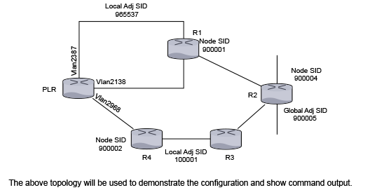
The above topology is used to demonstrate the configuration and show command output. You will see the backup paths that the PLR computes to protect the node segments of R1 and R2, the global adjacency segment on R2, and the local adjacency segment on the vlan 2387 on the PLR.
Here is a snippet of the configuration on the PLR.
switch(config)# interface vlan 2138
switch(config-if-Vl2138)# ip address 10.1.1.1/24
switch(config-if-Vl2138)# isis enable inst1
switch(config-if-Vl2138)# isis metric 11
switch(config-if-Vl2138)# isis network point-to-point

switch(config)# interface vlan2387
switch(config-if-Vl2138)# ip address 10.1.2.1/24
switch(config-if-Vl2138)# isis enable inst1
switch(config-if-Vl2138)# isis network point-to-point
switch(config-if-Vl2138)# adjacency-segment ipv4 p2p label 965537 backup-eligible

switch(config)# interface vlan2968
switch(config-if-Vl2968)# ip address 10.1.3.1/24
switch(config-if-Vl2968)# isis enable inst1
switch(config-if-Vl2968)# isis network point-to-point
switch(config-if-Vl2968)# isis fast-reroute ti-lfa mode disabled

…

switch(config)# router isis inst1
switch(config-isis)# net 49.0001.1111.1111.1001.00
switch(config-isis)# router-id ipv4 252.252.1.252
switch(config-isis)# is-type level-2
switch(config-isis)# timers local-convergence-delay 5000 protected-prefixes
   !
switch(config-isis)# address-family ipv4 unicast
switch(config-isis-af)# fast-reroute ti-lfa mode node-protection
   !

switch(config-isis)# segment-routing mpls
switch(config-isis-sr-mpls)# no shutdown
switch(config-isis-sr-mpls)# adjacency-segment allocation sr-peers backup-eligible
!
end
The protection of anycast segments does not need any new configuration. The above configuration enables protection of anycast segments.
To demonstrate the protection of anycast segments consider the following topology.
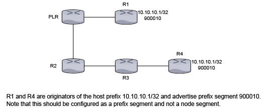
R1 and R4 are originators of the host prefix 10.10.10.1/32 and advertise prefix segment 900010. This must be configured as a prefix segment and not a node segment.
R1 and R4’s configuration should look similar to the following:
switch(confg)# router isis inst1
switch(config-router-isis)# interface Loopback0
switch(config-if-Lo0)# ip address 10.10.10.1/32
switch(config-if-Lo0)# isis enable inst1

!
...
switch(confg)# router isis inst1
switch(config-router-isis)# segment-routing mpls
switch(config-router-isis-sr-mpls)# prefix-segment 10.10.10.1/32 index 10
!
The prefix in the prefix-segment command must belong to an interface enabled with IS-IS or must be an active route in the RIB of another protocol redistributed into IS-IS.
When the link or node protection is configured on the PLR, then the primary path to the segment 900010 is PLR - R1 and the backup path is PLR - R2 - R3 - R4. In other words, the destination in the backup path is the segment originated by R4 as the segment originated by R1 and is not reachable when link PLR-R1 or the node R1 goes down.
show ip route
When services like LDP pseudowires, BGP LU, L2 EVPN, or L3 MPLS VPN use IS-IS SR tunnels as an underlay, these services are automatically protected by TI-LFA tunnels that protect the IS-IS SR tunnels. The show ip route command displays the hierarchy of the overlay-underlay-TI-LFA tunnels.
switch# show ip route
 B        2001:db8:3::/48 [200/0]
           via 2002::b00:301/128, IS-IS SR tunnel index 3, label 122697
		via TI-LFA tunnel index 5, label imp-null(3)
		via fe80::200:76ff:fe03:0, Ethernet26/1, label imp-null(3)
		backup via fe80::200:76ff:fe01:0, Ethernet30/1, label 900002 900003
IS-IS Dynamic Flooding Configuration
switch(config)# router isis Amun
switch(config-router-isis)# net 49.0000.0000.3333.00
switch(config-router-isis)# is-hostname ip3
switch(config-router-isis)# lsp flooding dynamic
Dynamic flooding should be enabled on all routers in the area. To enable Dynamic Flooding on all routers, use the following command:
lsp flooding dynamic [level-1 | level-2]
nolsp flooding dynamic [level-1 | level-2]
default lsp flooding dynamic [level-1 | level-2]
If necessary, the area leader election process can be tuned or disabled with the commands:
area leader [level-1 | level-2] priority 0-255 area leader [level-1 | level-2] disabled
no area leader [level-1 | level-2] priority 0-255 area leader [level-1 | level-2] disabled
default area leader [level-1 | level-2] priority 0-255 area leader [level-1 | level-2] disabled
Limitations
On a sparse topology, Dynamic Flooding is not effective and only adds overhead. Leaf-spine and Clos networks are appropriate dense topologies.
Relax Address-Family Check for IS-IS Adjacency
Address-Family Check for IS-IS creates the adjacency between devices with different address families. For example, a router supporting IPv4 and IPv6 is connected to a IPv4 only router, Address-Family Check is verified by comparing the NLPID TLV ( Type #129 ) advertised in IIH hellos exchanged between peers. It is useful in following scenarios.
Incrementally Enable IPv6 in an Existing IPv4 Network
Relaxing the Address-Family Check is useful to gradually add IPv6 support in an IPv4 network, without disturbing the IPv4 connectivity.
IPv4 Controller Peering IPv4/v6 Dual Stack Router
A controller forms an IS-IS adjacency with a router and uses the IS-IS database for topology discovery. If the controller only supports IPv4 IS-IS or only IPv4 tunnels, to relax the Address-Family Check on the dual stack IPv4/v6 router for adjacency is useful in establishment.
Disabling the Address-family Check
Under IS-IS instance, configure the following to disable the Address-Family Check during IIH processing.
switch(config-router-isis)# ?
   adjacency Configure parameters for adjacency formation
switch(config-router-isis)# adjacency?
   address-family Configure address-family related parameters for adjacency formation
switch(config-router-isis)# adjacency address-family?
   match Configure address-family match check related parameters for adjacency formation
switch(config-router-isis)# adjacency address-family match?
   disabled Relax address-family match check for bringing up adjacency
switch(config-router-isis)# adjacency address-family match disabled?
Show Command
switch# show isis neighbor detail
Instance  VRF      System Id        Type Interface   SNPA   State Hold time   Circuit Id
inst1     default  1111.1111.1002   L2   Vlan2116    P2P    UP    24          06
  Area Address(es): 49.0001
  SNPA: P2P
  Router ID: 1.0.0.2
  Advertised Hold Time: 30
  State Changed: 00:04:18 ago at 2020-11-01 22:28:35
  IPv4 Interface Address: 1.0.0.2
  IPv6 Interface Address: none
  Interface name: Vlan2116
  Graceful Restart: Supported
  Segment Routing Enabled
    SRGB Base: 900000 Range: 65536
    Adjacency Label IPv4: 149152
  Supported Address Families: IPv4, IPv6
Neighbor Supported Address Families: IPv4switch(config-router-isis)# show isis interface detail
IS-IS Instance: inst1 VRF: default
Interface Vlan2116:
Index: 35 SNPA: P2P
MTU: 1497 Type: point-to-point
Supported Address Families: IPv4, IPv4
Area Proxy Boundary is Disabled
BFD IPv4 is Disabled
BFD IPv6 is Disabled
Hello Padding is Enabled
Level 2:
Metric: 10, Number of adjacencies: 1
Link-ID: 23
Authentication mode: None
TI-LFA link protection is enabled for the following IPv4 segments: node segments, adjacency segments
TI-LFA protection is disabled for IPv6
Adjacency 1111.1111.1002:
State: UP, Level: 2 Type: Level 2 IS
Advertised Hold Time: 30
Neighbor Supported Address Families: IPv4
Address Family Match: Disabled
IPv4 Interface Address: 1.0.0.2
Areas:
49.0001Usage Guidelines
For IPv6 network upgrade, ensure the knob is incrementally configured on a contiguous section of the network, at any point the choice of routers for upgrade should not bisect the upgraded (supporting IPv4/v6) part of the network. All the routers bordering the upgraded network should always have the knob enabled.
- Enable the CLI knob.
- Enable IPv6 address family in the IS-IS instance.
- Configure IPv6 on all the IS-IS interfaces.
IS-IS Advertisement and Reachability of Interface Addresses
eos advertises IS-IS passive and active interfaces, but in some cases, you want to control the Time-to-Liveadvertisement of interface addresses on the switch. Configure IS-IS to advertise only passive interfaces and control the LSP size by stopping the advertisement of active interfaces and reduce the IS-IS convergence time in complex networks.
eos supports advertise ip-reachability passive-only to control the advertisement of IP Reachability TLVs. When enabled, IS-IS advertises IP Reachability for passive interfaces only.
Configuring IS-IS Interface Advertisement and Reachability
Use the following command to advertise TLVs from only passive interfaces on IS-IS instance, inst1:
switch(config)#router isis inst1
switch(config-router-isis)#advertise interface-address passive-only
Use the following command to advertise reachability TLVs from only passive interfaces on IS-IS instance, inst1:
switch(config)#router isis inst1
switch(config-router-isis)#advertise ip-reachability passive-only
Displaying IS-IS Interface Advertisement Information
Use the following command to display information about IS-IS Interface Advertisement:
switch#show running-config
        ...
        router isis inst1
        net 49.0001.1111.1111.1001.00
        is-hostname A
        is-type level-2
        lsp purge origination-identification
        log-adjacency-changes
        advertise interface-address passive-only
        advertise ip-reachability passive-only
        !
        address-family ipv4 unicast
        …
Displaying IS-IS Information
- Displaying the Link State Database
- Displaying the Interface Information for the IS-IS Instance
- Displaying IS-IS Neighbor Information
- Displaying IS-IS Instance Information
- Displaying IS-IS Segment Routing Information
- Displaying show isis local-convergence-delay
- Verifying IS-IS Graceful Restart (GR) Information
- IS-IS Dynamic Flooding Show Commands
Displaying the Link State Database
To display the link state database of IS-IS, use the show isis database command.
Example
switch# show isis database
ISIS Instance: Osiris
  ISIS Level 2 Link State Database
    LSPID                 Seq Num   Cksum  Life  IS Flags
    1212.1212.1212.00-00  4         714    1064  L2 <>
    1212.1212.1212.0a-00  1         57417  1064  L2 <>
    2222.2222.2222.00-00  6         15323  1116  L2 <>
    2727.2727.2727.00-00  10        15596  1050  L2 <>
    3030.3030.3030.00-00  12        62023  1104  L2 <>
    3030.3030.3030.c7-00  4         53510  1104  L2 <>
switch>
Displaying the Interface Information for the IS-IS Instance
To display interface information related to the IS-IS instance, use the show isis interface command.
Example
switch# show isis interface

ISIS Instance: Osiris
  Interface Vlan20:
    Index: 59 SNPA: 0:1c:73:c:5:7f
    MTU: 1497 Type: broadcast
    Level 2:
      Metric: 10, Number of adjacencies: 2
      LAN-ID: 1212.1212.1212, Priority: 64
      DIS: 1212.1212.1212, DIS Priority: 64
  Interface Ethernet30:
    Index: 36 SNPA: 0:1c:73:c:5:7f
    MTU: 1497 Type: broadcast
    Level 2:
      Metric: 10, Number of adjacencies: 1
      LAN-ID: 3030.3030.3030, Priority: 64
      DIS: 3030.3030.3030, DIS Priority: 64
switch>
Displaying IS-IS Neighbor Information
To display general information for IS-IS neighbors that the device sees, use show isis neighbors.
Example
switch# show isis neighbor
Inst Id   System Id       Type  Interface   SNPA          State  Hold time
10        2222.2222.2222  L2    Vlan20       2:1:0:c:0:0   UP    30
10        1212.1212.1212  L2    Vlan20       2:1:0:d:0:0   UP     9
10        3030.3030.3030  L2    Ethernet30   2:1:0:b:0:0   UP     9
switch>
Displaying IS-IS Instance Information
To display the system ID, Type, Interface, IP address, State and Hold information for IS-IS instances, use the show isis summary command. The command is also used to verify the configured maximum wait interval, initial wait interval, and hold time of SPF timers in IS-IS instances. This command also displays values of the current SPF interval, last Level-1 SPF run, and last Level-2 SPF run.
- This command displays general information about IS-IS
instances.
switch# show isis summary ISIS Instance: Osiris System ID: 1010.1040.1030, administratively enabled, attached Internal Preference: Level 1: 115, Level 2: 115 External Preference: Level 1: 115, Level 2: 115 IS-Type: Level 2, Number active interfaces: 1 Routes IPv4 only Last Level 2 SPF run 2:32 minutes ago Area Addresses: 10.0001 level 2: number dis interfaces: 1, LSDB size: 1 switch> - This command displays the SPF interval information about IS-IS
instances.
switch(config-router-isis-af)# show isis summary

IS-IS Instance: 1 VRF: default
 System ID: 0000.0000.0001, administratively enabled
 Multi Topology disabled, not attached
 IPv4 Preference: Level 1: 115, Level 2: 115
 IPv6 Preference: Level 1: 115, Level 2: 115
 IS-Type: Level 1 and 2, Number active interfaces: 0
 Routes both IPv4 and IPv6
                           Max wait(s) Initial wait(ms) Hold interval(ms)
 LSP Generation Interval:     5              50               50
 SPF Interval:                2            1000             1000
 Current SPF hold interval(ms): Level 1: 1000, Level 2: 1000
 Last Level 1 SPF run 1 seconds ago
 Last Level 2 SPF run 1 seconds ago
 Authentication mode: Level 1: None, Level 2: None
 Graceful Restart: Disabled, Graceful Restart Helper: Enabled
 Area Addresses:
   49.0001
 level 1: number dis interfaces: 0, LSDB size: 1
 level 2: number dis interfaces: 0, LSDB size: 1
Displaying IS-IS Segment Routing Information
show isis database detail
The show isis database detail command provides a view of LSPDB of different devices in the IS-IS domain. The output displays the TLVs and sub-TLVs that are being self-originated or the ones that have been received from other routers.
Example
switch# show isis database detail
ISIS Instance: inst1 VRF: default
 ISIS Level 2 Link State Database
 LSPID Seq Num Cksum Life IS Flags
 1111.1111.1001.00-00 10 63306 751 L2 <>
 NLPID: 0xCC(IPv4) 0x8E(IPv6)
 Area address: 49.0001
 Interface address: 1.0.7.1
 Interface address: 1.0.0.1
 Interface address: 2000:0:0:47::1
 Interface address: 2000:0:0:40::1
 IS Neighbor : lf319.53 Metric: 10
    LAN-Adj-sid: 100000 flags: [ L V ] weight: 0 system ID: 1111.1111.1002
 IS Neighbor (MT-IPv6): lf319.53 Metric: 10
    LAN-Adj-sid: 100001 flags: [ L V F ] weight: 0 system ID: 1111.1111.1002
 Reachability : 1.0.11.0/24 Metric: 1 Type: 1 Up
    SR Prefix-SID: 10 Flags: [ R ] Algorithm: 0
 Reachability : 1.0.3.0/24 Metric: 1 Type: 1 Up
 Reachability : 1.0.7.1/32 Metric: 10 Type: 1 Up
    SR Prefix-SID: 2 Flags: [ N ] Algorithm: 0
 Reachability : 1.0.0.0/24 Metric: 10 Type: 1 Up
 Reachability (MT-IPv6): 2000:0:0:4b::/64 Metric: 1 Type: 1 Up
    SR Prefix-SID: 11 Flags: [ R ] Algorithm: 0
 Reachability (MT-IPv6): 2000:0:0:43::/64 Metric: 1 Type: 1 Up
 Reachability (MT-IPv6): 2000:0:0:47::1/128 Metric: 10 Type: 1 Up
    SR Prefix-SID: 3 Flags: [ N ] Algorithm: 0
 Reachability (MT-IPv6): 2000:0:0:40::/64 Metric: 10 Type: 1 Up
 Router Capabilities: 252.252.1.252 Flags: [ ]
    SR Capability: Flags: [ I V ]
       SRGB Base: 900000 Range: 65536
 Segment Binding: Flags: [ F ] Weight: 0 Range: 1 Pfx 2000:0:0:4f::1/128
    SR Prefix-SID: 19 Flags: [ ] Algorithm: 0
 Segment Binding: Flags: [ ] Weight: 0 Range: 1 Pfx 1.0.15.1/32
    SR Prefix-SID: 18 Flags: [ ] Algorithm: 0
show isis segment-routing
The show isis segment-routing command displays the summary information on IS-IS SR status.
Example
switch(config)# show isis segment-routing
System ID: 1111.1111.1002               Instance: inst1
SR supported Data-plane: MPLS           SR Router ID: 252.252.2.252
SR Global Block( SRGB ): Base: 900000   Size: 65536
Adj-SID allocation mode: SR-adjacencies
Adj-SID allocation pool: Base: 100000     Size: 16384
All Prefix Segments have    : P:0 E:0 V:0 L:0
All Adjacency Segments have : F:0 B:0 V:1 L:1 S:0
ISIS Reachability Algorithm : SPF (0)
Number of ISIS segment routing capable peers: 3
Self-Originated Segment Statistics:
Node-Segments       : 2
Prefix-Segments     : 2
Proxy-Node-Segments : 0
Adjacency Segments  :
About the Output
The first line of the output shows the IS-IS system ID of this device and the name of the instance with which IS-IS is configured.
The supported data plane is shown against the SR supported Data-plane field whereas the Router ID being advertised in the Router Capability is mentioned in the SR Router ID Field.
The SRGB in use and the MPLS label pool being used for adjacency segment allocation are mentioned in this output. The current adjacency allocation mode which refers to whether we are allocating adjacency segments to all IS-IS adjacencies or only those adjacencies which support SR or None of the adjacencies is shown in the Adj-SID allocation mode field.
Flag contents of All Prefix Segments originated on this router, Flag contents of All Adjacency Segments originated on this router and supported IS-IS Reachability Algorithm have been provided through this command output and they carry the meaning as per the IS-IS SR IETF draft.
This show command provides a statistics related to IS-IS SR in terms of various counters ranging from number of IS-IS SR enabled peers, number of Node-SIDs, prefix-SIDs, proxy-node-segments and adjacency segments being originated on this router in IS-IS.
The show isis segment-routing command also provides information if segment routing has been administratively disabled as shown.
switch(config-router-isis-sr-mpls)# show isis segment-routing
! IS-IS (Instance: inst1) Segment Routing has been administratively shutdown
show isis segment-routing global-blocks
The show isis segment-routing global-blocks command lists the SRGBs in use by all SR supporting devices in IS-IS domain including the SRGB in use by IS-IS SR on this device.
Example
switch# show isis segment-routing global-blocks
System ID: 1111.1111.1002              Instance: inst1
SR supported Data-plane: MPLS          SR Router ID: 252.252.2.252
SR Global Block( SRGB ): Base: 900000  Size: 65536
Number of ISIS segment routing capable peers: 3
SystemId             Base         Size
-------------------- ------------ -----
1111.1111.1002        900000      65536
1111.1111.1001        900000      65536
show isis segment-routing prefix-segments
The show isis segment-routing prefix-segments command provides the details of all prefix segments being originated as well the segments received from IS-IS SR speakers in the domain.
Example
switch# show isis segment-routing prefix-segments
System ID: 1111.1111.1002         Instance: inst1
SR supported Data-plane: MPLS     SR Router ID: 252.252.2.252
Node: 2 Proxy-Node: 2 Prefix: 2 Total Segments: 6
Flag Descriptions: R: Re-advertised, N: Node Segment, P: no-PHP
                   E: Explicit-NULL, V: Value, L: Local
Segment status codes: * - Self originated Prefix, L1 - level 1, L2 - level 2
Prefix        SID     Type        Flags                    SystemID        Type
--------------------- ---------   ----------------         ---------------------
 1.0.7.1/32    2      Node        R:0 N:1 P:0 E:0 V:0 L:0   1111.1111.1001  L1
* 1.0.8.1/32   4      Node        R:0 N:1 P:0 E:0 V:0 L:0   1111.1111.1002  L2
 1.0.11.0/24   10     Prefix      R:1 N:0 P:0 E:0 V:0 L:0   1111.1111.1001  L2
* 1.0.12.0/24  12     Prefix      R:1 N:0 P:0 E:0 V:0 L:0   1111.1111.1002  L2
 1.0.15.1/32   18     Proxy-Node  R:0 N:0 P:0 E:0 V:0 L:0   1111.1111.1001  L2
 1.0.16.1/32   20     Proxy-Node  R:0 N:0 P:0 E:0 V:0 L:0   1111.1111.1003  L2
About the Output
After the usual output header that represents the system ID, instance name, etc and parameters of a router, there is a line depicting prefix segment counters. Each field in this line relates to the number of segments that are present in this routers IS-IS instance. For example, the above example shows that this device has 2 Node Segments (Self originated as well as the ones received from other IS-IS SR devices).
The main section of this show commands output is the section that lists all the prefix segments and related information like prefix, SID, type of segment (Prefix, Node, Proxy-Node), the flag values being carried in the sub-TLVs of these prefix segments and the system ID of the originating router. The Type field will be useful on a IS type level-1-2 router. It shows whether the installed prefix segment is from a level-1 prefix or a level-2 prefix.
show isis segment-routing prefix-segments self-originated
The show isis segment-routing prefix-segments self-originated command output is identical to show isis segment-routing prefix-segments except, the fact that the former lists only self-originated prefix segments.
show isis segment-routing adjacency-segments
The show isis segment-routing adjacency-segments displays list of all the adjacency segments that are being originated by IS-IS SR on a router.
Example
switch# show isis segment-routing adjacency-segments
System ID: 1111.1111.1002           Instance: inst1
SR supported Data-plane: MPLS       SR Router ID: 252.252.2.252
Adj-SID allocation mode: SR-adjacencies
Adj-SID allocation pool: Base: 100000     Size: 16384
Adjacency Segment Count: 4
Adj IP-address     Local     Intf    Label    SID  Source     Flags      Type
-----------------  --------  ------  ------   ---  ---------  ---------  --------
1.0.0.1            Vlan2472  100000  Dynamic  F:0   B:0 V:1    L:1 S:0   LAN L2
1.0.1.2            Vlan2579  100001  Dynamic  F:0   B:0 V:1    L:1 S:0   P2P L2
fe80::1:ff:fe01:0  Vlan2472  100002  Dynamic  F:0   B:0 V:1    L:1 S:0   LAN L2
fe80::1:ff:fe02:0  Vlan2579  100003  Dynamic  F:0   B:0 V:1    L:1 S:0   P2P L2
About the Output
It consists allocation mode, MPLS label pool from which labels would be allocated to adjacencies, total count of adjacency segments allocated so far and the default flag values carried in all adj-SID sub-TLVs originating from this device.
The main section of the output lists all the adjacency segments allocated so far in six columns each pertaining to Adjacency IP address, local interface name, MPLS label value, SID source, flags in the sub-TLV and the type of adj-SID respectively. The type of the adjacency segments depends on the IS-IS type of adjacency and the IS level.
show mpls label ranges
The show mpls label ranges command displays the MPLS label range available on a router is categorized into different pools which cater to different applications running on the router.
The isis-sr refers to the SRGB use-case in IS-IS, and isis (dynamic) refers to the label pool that is used for dynamic allocation of adjacency segments in IS-IS.
Example
switch# show mpls label ranges
Start    End      Size     Usage
-----------------------------------------
0        15       16       reserved
16       99999    99984    static mpls
100000   116383   16384    isis (dynamic)
116384   362143   245760   free (dynamic)
362144   899999   537856   unassigned
900000   965535   65536    isis-sr
show mpls segment-routing bindings
The show mpls segment-routing bindings command displays the local label bindings and label bindings on the peer routers for each prefix that has a segment advertised. Peer ID here represents the IS-IS system ID of the peer.
Example
switch# show mpls segment-routing bindings
1.0.7.1/32
 Local binding: Label: 900002
 Remote binding: Peer ID: 1111.1111.1001, Label: imp-null
 Remote binding: Peer ID: 1111.1111.1003, Label: 900002
1.0.8.1/32
 Local binding: Label: imp-null
 Remote binding: Peer ID: 1111.1111.1001, Label: 900004
 Remote binding: Peer ID: 1111.1111.1003, Label: 900004
1.0.9.1/32
 Local binding: Label: 900006
 Remote binding: Peer ID: 1111.1111.1001, Label: 900006
 Remote binding: Peer ID: 1111.1111.1003, Label: imp-null
show mpls lfib route
The show mpls lfib route command displays the LFIB. Each LFIB entry has In-Label, Out-Label, metric, payload type, nexthop information, etc. fields. The source column depicts the MPLS control plane protocol that is responsible for the label binding that resulted in this LFIB route.
Example
switch# show mpls lfib route
MPLS forwarding table (Label [metric] Vias) - 7 routes
MPLS next-hop resolution allow default route: False
Via Type Codes:
        M - Mpls Via, P - Pseudowire Via,
        I - IP Lookup Via, V - Vlan Via,
        VA - EVPN Vlan Aware Via, ES - EVPN Ethernet Segment Via,
        VF - EVPN Vlan Flood Via, AF - EVPN Vlan Aware Flood Via,
        NG - Nexthop Group Via
Source Codes:
        S - Static MPLS Route, B2 - BGP L2 EVPN,
        B3 - BGP L3 VPN, R - RSVP,
        P - Pseudowire, L - LDP,
        IP - IS-IS SR Prefix Segment, IA - IS-IS SR Adjacency Segment,
        IL - IS-IS SR Segment to LDP, LI - LDP to IS-IS SR Segment,
        BL - BGP LU, ST - SR TE Policy,
        DE - Debug LFIB

 IA 100000 [1]
            via M, 1.0.1.2, pop
            payload autoDecide, ttlMode uniform, apply egress-acl
            interface Vlan2930
 IA 100001 [1]
            via M, fe80::200:eff:fe02:0, pop
            payload autoDecide, ttlMode uniform, apply egress-acl
            interface Vlan2930
 IP 900008 [1]
            via M, 1.0.1.2, swap 900008
            payload autoDecide, ttlMode uniform, apply egress-acl
            interface Vlan2930
 IP 900009 [1]
            via M, fe80::200:eff:fe02:0, swap 900009
            payload autoDecide, ttlMode uniform, apply egress-acl
            interface Vlan2930
show mpls lfib route <label value>
The show mpls lfib route <label value> command provides information relevant to just the label value passed as an extension to the show command.
Example
switch# show mpls lfib route 900008
MPLS forwarding table (Label [metric] Vias) - 7 routes
MPLS next-hop resolution allow default route: False
Via Type Codes:
        M - Mpls Via, P - Pseudowire Via,
        I - IP Lookup Via, V - Vlan Via,
        VA - EVPN Vlan Aware Via, ES - EVPN Ethernet Segment Via,
        VF - EVPN Vlan Flood Via, AF - EVPN Vlan Aware Flood Via,
        NG - Nexthop Group Via
Source Codes:
        S - Static MPLS Route, B2 - BGP L2 EVPN,
        B3 - BGP L3 VPN, R - RSVP,
        P - Pseudowire, L - LDP,
        IP - IS-IS SR Prefix Segment, IA - IS-IS SR Adjacency Segment,
        IL - IS-IS SR Segment to LDP, LI - LDP to IS-IS SR Segment,
        BL - BGP LU, ST - SR TE Policy,
        DE - Debug LFIB
 IP 900008 [1]
            via M, 1.0.1.2, swap 900008
            payload autoDecide, ttlMode uniform, apply egress-acl
            interface Vlan2930
Displaying show isis local-convergence-delay
The show isis local-convergence-delay command shows the current or last attempt at delaying the convergence of protected routes on a link down/BFD neighbor down event. If the timer aborts for some reason (such as a topology change causing a new SPF), the attempt fails.
switch# show isis local-convergence-delay

IS-IS Instance: inst1 VRF: default
  System ID: 1111.1111.1001
  IPv4 local convergence delay configured, 5000 msecs
  IPv6 local convergence delay configured, 5000 msecs
  Level 1 attempts 0, failures 0
  Level 2 attempts 3, failures 1

  Level 2 in progress due to LINK DOWN on Vlan2138
    TI-LFA node protection is enabled for IPv4
    IPv4 Routes delayed: 0
      Delay timer started at: 2019-07-25 23:16:33
      Delay timer expires in 2 secs
    TI-LFA protection is disabled for IPv6

  Level 2 last attempt due to LINK DOWN on Vlan2138, Succeeded
    TI-LFA node protection is enabled for IPv4
    IPv4 Routes delayed: 3
      Delay timer started at: 2019-07-25 23:14:51
      Delay timer stopped at: 2019-07-25 23:14:56
    TI-LFA protection is disabled for IPv6
The detail keyword also lists all the routes that have been delayed.
switch# show isis local-convergence-delay detail
  ...
  Level 2 last attempt due to LINK DOWN on Vlan2138, Succeeded
    TI-LFA node protection is enabled for IPv4
    IPv4 Routes delayed: 3
      Delay timer started at: 2019-07-25 23:14:51
      Delay timer stopped at: 2019-07-25 23:14:56
      Delayed routes:
        10.0.7.1/32
        10.0.9.1/32
        10.0.10.1/32
    TI-LFA protection is disabled for IPv6
Verifying IS-IS Graceful Restart (GR) Information
- Last Start/Restart was completed successfully.
- Last Start/Restart exited after t2 (level-1/level-2) expiry.
- Last Restart exited after t3 expiry.
- Start/Restart in progress.
- Graceful Restart was disabled during startup.
- The show isis graceful-restart vrf [vrf-name] command displays
the GR configuration and graceful-restart related state of the IS-IS instance as well as
its
neighbors.Example
switch# show isis graceful-restart vrf default IS-IS Instance: 1 VRF: default System ID: 0000.0000.0001 Graceful Restart: Enabled, Graceful Restart Helper: Enabled State: Last Start exited after T2 (level-1) expiry T1 : 3s T2 (level-1) : 30s/20s remaining T2 (level-2) : 30s/not running T3 : not running System ID Type Interface Restart Capable Status is-hostname-1 L1L2 Ethernet1 Yes Running is-hostname-2 L1 Ethernet2 Yes Restarting - The show isis summary vrf [vrf-name] command displays the
graceful restart state and helper
configuration.Example
switch# show isis summary vrf default IS-IS Instance: 1 VRF: default System ID: 0000.0000.0001, administratively enabled .... Graceful Restart: Enabled, Graceful Restart Helper: Enabled - The show isis neighbors detail vrf [vrf-name] command displays
the helpers view of a restarting
router.Example
switch# show isis neighbors detail vrf default Instance VRF System Id Type Interface SNPA State Hold time Circuit Id 1 default OT1 L1 Ethernet1 2:1:0:b 4:0:0 UP 29839 OT3.05 Area Address(es): 49.0001 SNPA: 2:1:0:b4:0:0 .... Graceful Restart: Supported, Status: Restarting (RR rcvd, RA sent, CSNP sent) - The show isis interface detail vrf [vrf-name] command displays
the graceful restart related stats for that
interface.Example
switch# show isis interface detail vrf default
ISIS Instance: ISISQ VRF: default
  Interface Ethernet1:
    Index: 2 SNPA: P2P
    ...
    Level 1:
      Graceful Restart Status: RR sent, SA sent, RA rcvd, CSNP rcvd
IS-IS Dynamic Flooding Show Commands
switch# show isis dynamic flooding topology

IS-IS Instance: Amun VRF: default
  Level 1:
    Path: ip6.00 ip4.00 ip2.00 ip1.00 ip3.00 ip5.00 ip6.00
This command displays a list of paths that describe the flooding topology. Each path is a list of nodes in the network.
switch# show isis dynamic flooding interfaces

IS-IS Instance: Amun VRF: default
  Level 1:
    Ethernet5
    Ethernet4
This shows that the system is currently flooding only on ethernet4 and ethernet5. Normally at least two interfaces are selected.
IS-IS Commands
Global Configuration Commands
Clear Commands
Interface Configuration Commands
- adjacency-segment
- adjacency-segment (allocation)
- adjacency-segment (static)
- area leader
- authentication key
- authentication mode
- bfd all-interfaces
- isis address-family fast-reroute ti-lfa srlg
- isis authentication key
- isis authentication mode
- isis bfd
- isis enable
- isis fast-reroute ti-lfa mode
- isis hello-interval
- isis hello-multiplier
- isis ipv6 metric
- isis lsp tx interval
- isis metric
- isis multi-topology
- isis network
- isis passive
- isis priority
Router IS-IS Configuration Mode (Includes Address-Family Mode)
- address-family
- advertise interface-address passive-only
- advertise ip-reachability passive-only
- fast-reroute ti-lfa mode
- fast-reroute ti-lfa srlg
- graceful-restart (IS-IS)
- is-hostname
- is-type
- log-adjacency-changes (IS-IS)
- lsp dynamic flooding
- match isis level
- multi-topology
- net
- passive (IS-IS)
- redistribute (IS-IS)
- redistribute bgp route-map
- set isis level
- set-overload-bit
- shutdown (IS-IS)
- spf-interval
IS-IS Segment Routing Commands
TWAMP Commands
Display Commands EXEC Mode
- show isis database
- show isis database detail
- show isis dynamic flooding
- show isis graceful-restart vrf
- show isis hostname
- show isis interface
- show isis local-convergence-delay
- show isis neighbors
- show isis network topology
- show isis segment-routing
- show isis segment-routing adjacency-segments
- show isis segment-routing global-blocks
- show isis segment-routing prefix-segments
- show isis segment-routing tunnel
- show isis summary
- show isis ti-lfa path
- show isis ti-lfa tunnel
- show monitor twamp-light counters
- show monitor twamp-light raw count
- show monitor twamp-light
- show mpls label ranges
- show mpls lfib route
- show mpls segment-routing bindings
- show tunnel fib
address-family
The address-family command places the switch in address-family configuration mode.
Address-family configuration mode is not a group change mode; running-config is changed immediately after commands are executed. The exit command does not affect the configuration.
- ipv4-unicast
- ipv6-unicast
The no address-family and default address-family commands delete the specified address-family from running-config by removing all commands previously configured in the corresponding address-family mode.
The exit command returns the switch to the isis configuration mode.
Command Mode
Router-IS-IS Configuration
Command Syntax
address-family [ipv4 | ipv6][MODE]
no address-family [ipv4 | ipv6][MODE]
default address-family [ipv4 | ipv6][MODE]
Parameters
- address_family Options include:
- ipv4 IPv4 unicast.
- ipv6 IPv6 unicast.
- MODE Options include:
- no parameter Defaults to unicast.
- unicast All IPv4 or IPv6 addresses are active.
- These commands enter the address family mode for IPv4
unicast.
switch(config)# router isis Osiris switch(config-router-isis)# address-family ipv4 unicast switch(config-router-isis-af)# - To exit from the IPv4 IS-IS unicast address family
configuration mode, enter the following
command.
switch(config)# router isis Osiris
switch(config-router-isis)# address-family ipv4 unicast
switch(config-router-isis-af)# exit
switch(config-router-isis)#
adjacency-segment
Use the adjacency-segment command in the interface configuration mode to have the PLR computes backup paths for an adjacency segment only if the Adjacency SID sub-TLV has the B-flag (backup flag) set.
Command Mode
Interface configuration mode
Command Syntax
adjacency-segment [ipv4|ipv6] p2p [multiple][label label | indexindex] backup-eligible
no adjacency-segment [ipv4 | ipv6]p2p [multiple][label label|index index] backup-eligible
default adjacency-segment [ipv4 | ipv6]p2p multiple][label label|index index] backup-eligible
- ipv4 IPv4 related.
- ipv6 IPv6 related.
- p2p P2P interface type.
- multiple Configure multiple Adj-SIDs.
- label label Label value to be assigned as Adj-SID for adjacency on this interface. label range 16 -1048575.
- index index Prefix segment identifier. index range 0-65535.
- backup-eligible Eligible for protection.
adjacency-segment (allocation)
The adjacency-segment command allocates adjacency segments to all IS-IS adjacencies, or only those adjacencies which are to IS-IS routers that have advertised IS-IS SR capability, or to none of the adjacencies.
Command Mode
Segment-Routing MPLS Configuration
Command Syntax
adjacency-segment allocation [all-interface |none | sr-peers]
Parameters
- allocation Allocation of Adjacency Segments.
- all-interface Allocates adjacency segments to all IS-IS adjacencies.
- none Disable automatic adjacency segment allocation.
- sr-peers Allocate adjacency segments to IS-IS adjacencies with SR peers.
Example
switch(config-router-isis-sr-mpls)# adjacency-segment allocation sr-peeradjacency-segment (static)
The adjacency-segment command configures IS-IS adjacencies statically on the switch, so that these values are preserved even when the switch restarts. The no and the default form of the command places the switch back to the global configuration mode.
Command Mode
Interface Ethernet Configuration
Command Syntax
adjacency-segment ipv4 | ipv6 p2p [[label label-value]|[index index-value global]]
Parameters
- ipv4 IS-IS SR adjacency segment IPv4 interface configuration.
- ipv6 IS-IS SR adjacency segment IPv6 interface configuration.
- label label-value Label value to be assigned as Adj-SID for adjacency on this interface. Value ranges from 16 to 1048575.
- index label-value Index to be assigned as Adj-SID for adjacency on this interface. Value ranges from 0 to 65535.
- global global adjacency SID.
Example
switch(config-if-Et1)# adjacency-segment ipv4 p2p index 50 globaladvertise interface-address passive-only
The advertise interface-address passive-only command configures IS-IS to advertise interface addresses for passive interfaces. The no disables the configuration.
Configuration Mode
Router IS-IS Configuration
Command Syntax
advertise interface-address passive-only
Example
switch(config)# router isis inst1
switch(config-router-isis)#advertise interface-address passive-only
advertise ip-reachability passive-only
The advertise ip-reachability passive-only allows the configuration of advertising IS-IS IP reachability TLVs for passive and nonpassive interfaces. This reduces the size of the LSP by stopping the advertisement of IP reachability addresses for active interfaces and reduce IS-IS convergence time in complex networks. The no version of the command disables the feature.
Configuration Mode
Router IS-IS Configuration
Command Syntax
advertise ip-reachability passive-only
Example
switch(config)#router isis inst1
switch(config-router-isis)#advertise ip-reachability passive-only
area leader
Use the area leader command to tune or disable the area leader election process.
Command Mode
Router configuration mode
Command Syntax
area leader [disabled | level-1 [disabled] | level-2 [disabled] | priority [num [level-1 | level-2]]]
no area leader
default area leader
- disabled Disables becoming the are leader.
- level-1 Configure at Level 1.
- disabled Disables becoming the are leader.
- level-2 Configure at Level 2.
- disabled Disables becoming the are leader.
- priority Sets the area leader priority.
- level-1 Configure at Level 1.
- level-2 Configure at Level 2.
authentication key
Theauthentication key command configures the authentication key for the IS-IS instance causing LSPs, CSNPs and PSNPs to be authenticated.
The no authentication key and default authentication key commands disables the authentication key for the IS-IS instance.
Command Mode
ISIS-Router Configuration
Command Syntax
authentication key [0 | 7] [LAYER_VALUE]
no authentication key [0 | 7] [LAYER_VALUE]
default authentication key [0 | 7] [LAYER_VALUE]
Parameters
- level-1
- level-2
Example
switch(config)# router isis 1
switch(config-router-isis)# authentication key secret
switch(config-router-isis)#
authentication mode
The authentication mode command configures authentication for the IS-IS instance causing LSPs, CSNPs, and PSNPs to be authenticated.
The no authentication mode and default authentication mode commands disables authentication for the IS-IS instance.
Command Mode
ISIS-Router Configuration
Command Syntax
authentication mode [md5 | text] [LAYER_VALUE]
no authentication mode [md5 | text] [LAYER_VALUE]
default authentication mode [md5 | text] [LAYER_VALUE]
Parameters
- LAYER_VALUE Layer value. Options include:
- level-1
- level-2
Example
switch(config)# router isis 1
switch(config-router-isis)# authentication mode md5
switch(config-router-isis)#
bfd all-interfaces
The bfd all-interfaces command enables Bidirectional Forwarding Detection (BFD) for all IS-IS-enabled interfaces in the IPv4 or IPv6 address family.
Use the isis bfd command to configure BFD on a specific interface.
Command Mode
Router-IS-IS Address-Family Configuration
Command Syntax
bfd all-interfaces
Example
switch(config)# router isis 1
switch(config-router-isis)# address-family ipv4
switch(config-router-af)# bfd all-interfaces
switch(config-router-af)#
clear isis database
The clear isis database command clears a specific LSP with a predefined LSP ID, or LSPs at a given level, or all LSPs in the database. Additionally, the command sends purge LSPs throughout the network to clear LSPs from all devices.
Command Mode
Privileged Exec
Command Syntax
clear isis [INSTANCE] database {LSPID | all | level-1 | level-2}
- INSTANCE Clears all LSPs from a specific LSP instance.
- LSPID Clears an LSP based on the specific LSP ID.
- all Clears all LSPs from the LSP database.
- level-1 Clears LSPs at level 1 only.
- level-2 Clears LSPs at level 2 only.
- This command clears all LSPs for the specific LSP ID of
1111.1111.1002.00-00.
switch(config)# clear isis database 1111.1111.1002.00-00 1 LSPs cleared on instance 1. switch(config)# - This command clears all LSPs from the LSP database.
switch(config)# clear isis database all 3 LSPs cleared on instance 1. switch(config)# - This command clears all LSPs from the level 1 LSP database.
switch(config)# clear isis database level-1 3 LSPs cleared on instance 1. switch(config)# - This command clears all LSPs from a specific LSP instance instance2.
switch(config)# clear isis instance2 database all
3 LSPs cleared on instance instance 2.
switch(config)#
clear isis instance
the clear isis instance clears an IS-IS instance or all instances.
Command Mode
Global
Command Syntax
clear isis instance vrf vrf_name
Parameters
vrf vrf_name - Clears an IS-IS instance from a named VRF.
Example
switch# clear isis instance
IS-IS instance 1 cleared.
clear isis neighbor
The clear isis neighbor command clears IS-IS adjacencies that exist on an interface, or at a specific level, or the adjacencies formed with a given neighbor (either with a system ID or a hostname).
Command Mode
Privileged EXEC
Command Syntax
clear isis neighbor {Neighbor-ID | all | interface} [level-1 | level-2 | level-1-2]
Parameters
- Neighbor-ID Clears adjacencies based on the system ID or the hostname of a neighbor.
- all Clears all adjacencies.
- interface Clears adjacencies for a specific interface.
- level-1 level 1 only.
- level-1-2 level 1-2 point-to-point only.
- level-2 level 2 only.
- This command clears IS-IS adjacencies with a neighbor
af86.3032.1a0f.
switch# clear isis neighbor af86.3032.1a0f 2 neighbors cleared on instance 1 switch# - This command clears all IS-IS adjacencies on an interface
et1.
switch# clear isis neighbor interface et1 4 neighbors cleared on instance 1 switch# - This command clears IS-IS adjacencies with a neighbor
af86.3032.1a0f and on interface
et1.
switch# clear isis neighbor af86.3032.1a0f interface et1 2 neighbors cleared on instance 1 switch# - This command clears all IS-IS adjacencies at Level 1 and on interface
et1.
switch# clear isis neighbor interface et1 level-1 2 neighbors cleared on instance 1 switch# - This command clears Level 1-2 point-to-point adjacencies
only.
switch# clear isis neighbor all level-1-2
0 neighbors cleared on instance 1
switch#
fast-reroute ti-lfa mode
Use the fast-reroute ti-lfa mode to enable link or node protection for node segments and adjacency segments of a specific address-family learned on all IS-IS interfaces.
Command Mode
address-family sub-mode of the router isis mode (config-router-isis-af)
Command Syntax
fast-reroute ti-lfa mode [[[ link-protection | node-protection][level-1 | level-2]] | disabled]
- link-protection Protects against the failure of the link.
- node-protection Protects against the failure of the neighbor mode.
- level-1 Protects prefixes only in level-1.
- level-2 Protects prefixes on in level-2. Disables the fast-reroute TI-LFA mode.
Guidelines
FRR using TI-LFA is disabled globally by default in the router IS-IS address-family sub-modes.
The interface TI-LFA configuration inherits the address-family sub-mode configuration by default.
fast-reroute ti-lfa srlg
Use the fast reroute ti-lfa srlg command to enable SRLG protection on all interfaces. This command is used in addition to configuring link-protection or node-protection. When SRLG protection is enabled, the backup paths are computed after excluding all the links that share the same SRLG with the active link that is being used by all prefix segments and adjacency segments.
Command Mode
IS-IS router address-family configuration mode
Command Syntax
fast-reroute ti-lfa srlg [strict]
Parameters
strict The backup path is only programmed if a backup path that excludes all the SRLGs configured on the primary interface.
graceful-restart (IS-IS)
The graceful-restart command configures IS-IS graceful-restart. The command provides options to configure the t2 time or the restart-hold-time.
t2 is the maximum wait time for the LSP database to synchronize (SPF computation is not done while t2 is running). t2 can be configured for either Level-1 or Level-2 routes.
restart-hold-time is the hold time advertised by the router to its neighbors before undergoing ASU2 fast reboot.
The no graceful-restart and default graceful-restart commands disables the IS-IS graceful-restart configuration from running-config.
Command Mode
Router-IS-IS Configuration
Command Syntax
graceful-restart t2 | restart-hold-time value
no graceful-restart t2 | restart-hold-time value
default graceful-restart t2 | restart-hold-time value
Parameters
- value The time in seconds. Value ranges from 5 to 300 seconds.
- restart-hold-time Sets the hold time when restarting.
- t2 Sets the LSP database sync wait time.
- In this example an ISIS graceful restart is configured with t2 wait time of
30 seconds for Level-1
routes.
switch(config)# router isis 1 switch(config-router-isis)# graceful-restart t2 level-1 30 - In this example an ISIS graceful restart is configured with
restart-hold-time of 50
seconds.
switch(config)# router isis 1
switch(config-router-isis)# graceful-restart restart-hold-time 50
is-hostname
The is-hostname command configures the use of a human-readable string to represent the symbolic name of an IS-IS router. It also changes the output of IS-IS show commands, to show the IS-IS hostname in place of system IDs if the corresponding IS-IS hostname is known. However, syslogs still use IS-IS system IDs and not the IS-IS hostname.
By default, if a hostname is configured on the switch, it is used as the IS-IS hostname. It is also possible to unconfigure an assigned hostname for IS-IS using the no is-hostname command. When the IS-IS hostname is removed, the switch goes back to using the switch's hostname as the IS-IS hostname.
Command Mode
Router-IS-IS Configuration
Command Syntax
is-hostname string
no is-hostname
- These commands configure the IS-IS hostname to the symbolic name
ishost1 for the IS-IS
router.
switch(config)# router isis inst1 switch(config-router-isis)# is-hostname ishost1 switch(config-router-isis)# - These commands unconfigure the IS-IS hostname of the symbolic name
ishost1 for the IS-IS
router.
switch(config)# router isis inst1
switch(config-router-isis)# no is-hostname ishost1
switch(config-router-isis)#
isis authentication key
The isis authentication key command configures the authentication key on the interface causing IS-IS Hellos to be authenticated.
The no isis authentication mode and default isis authentication mode commands disables the authentication key for the IS-IS instance.
Command Mode
Interface-Ethernet Configuration
Command Syntax
isis authentication key [0 | 7] [LAYER_VALUE]
no isis authentication key [0 | 7] [LAYER_VALUE]
default isis authentication key [0 | 7] [LAYER_VALUE]
Parameters
- level-1
- level-2
Example
switch(config)# interface Ethernet 3/6
switch(config-if-Et3/6)# isis authentication mode text
switch(config-if-Et3/6)# isis authentication key 7 cAm28+9a/xPi04o7hjd8Jw==
switch(config-if-Et3/6)#
isis authentication mode
The isis authentication mode command configures authentication on the interface causing IS-IS Hellos to be authenticated.
The no isis authentication mode and default isis authentication mode commands disables authentication for the IS-IS instance.
Command Mode
Interface-Ethernet Configuration
Command Syntax
isis authentication mode [md5 | text][LAYER_VALUE]
no isis authentication mode [md5 | text][LAYER_VALUE]
default isis authentication mode [md5 | text][LAYER_VALUE]
Parameters
- level-1
- level-2
Example
switch(config)# interface Ethernet 3/6
switch(config-if-Et3/6)# isis authentication mode text
switch(config-if-Et3/6)# isis authentication key 7 cAm28+9a/xPi04o7hjd8Jw==
switch(config-if-Et3/6)#
isis bfd
The isis bfd command activates the corresponding IS-IS routing instance on the configuration mode interface. By default, the IS-IS routing instance is not enabled on an interface.
The no isis enable and default isis enable commands disable IS-IS on the configuration mode interface by removing the corresponding isis enable command from running-config.
Command Mode
Interface-Ethernet Configuration
Command Syntax
isis bfd
no isis bfd
default isis bfd
Example
switch(config)# interface Ethernet 5/6
switch(config-if-Et5/6)# isis bfd
switch(config-if-Et5/6)#
isis enable
The isis enable command activates the corresponding IS-IS routing instance on the configuration mode interface. By default, the IS-IS routing instance is not enabled on an interface.
The no isis enable and default isis enable commands disable IS-IS on the configuration mode interface by removing the corresponding isis enable command from running-config.
Command Mode
Interface-Ethernet Configuration
Interface-Loopback Configuration
Interface-Port-channel Configuration
Interface-VLAN Configuration
Command Syntax
isis enable instance_id
no isis enable
default isis enable
Parameters
instance_id IS-IS instance name.
- These commands enable the IS-IS protocol on the interface
ethernet
4.
switch(config)# router isis Osiris switch(config-router-isis)# net 49.0001.1010.1040.1030.00 switch(config-router-isis)# interface ethernet 4 switch(config-if-Eth4)# isis enable Osiris - These commands disable the IS-IS protocol on the interface
ethernet
4.
switch(config)# interface ethernet 4
switch(config-if-Eth4)# no isis enable
isis fast-reroute ti-lfa mode
Use the isis fast-reroute ti-lfa mode command to enable link or node protection for node segments and adjacency segments learned on a specific IS-IS interface. By default, the interface TI-LFA configuration inherits the address-family sub-mode configuration.
The no isis fast-reroute ti-lfa and default isis fast-reroute ti-lfa mode commands disable link or node protection for node segments and adjacency segments learned on a specific IS-IS interface.
Command Mode
Router IS-IS Configuration Mode
Command Syntax
isis fast-reroute ti-lfa mode [link-protection | node-protection | disabled][level-1 | level-2]
no isis fast-reroute ti-lfa mode [link-protection | node-protection | level-1 | level-2]
default isis fast-reroute ti-lfa mode [link-protection | node-protection | disabled][level-1 | level-2]
Parameters
- link-protection - Configures link-protection.
- node-protection - Configures node-protection.
- disabled - Disables protection over the link.
- level-1 - Optional parameter in the Router Is-Is Address-family Configuration Mode - Restricts protection to node segments and adjacency segments learned through either Level-1 topologies only.
- level-2 - Optional parameter in both the Router Is-Is Address-family Configuration Mode that restricts protection to node segments and adjacency segments learned through Level-2 topologies only.
Example
switch(config)# router isis network1 instance-id 24
switch(config-router-isis)# address-family ipv4
switch(config-router-isis-af)# fast-reroute ti-lfa mode link-protection level 1
isis hello-interval
The isis hello-interval command sends Hello packets from applicable interfaces to maintain the adjacency through the transmitting and receiving of Hello packets. The Hello packet interval can be modified.
The no isis hello-interval and default isis hello-interval commands restore the default hello interval of 10 seconds on the configuration mode interface by removing the isis hello-interval command from running-config.
Command Mode
Interface-Ethernet Configuration
Interface-Loopback Configuration
Interface-Port-channel Configuration
Interface-VLAN Configuration
Command Syntax
isis hello-interval time
no isis hello-interval
default isis hello-interval
Parameters
time Values range from 1 to 300; default is 10.
- These commands configure a hello interval of 45
seconds for vlan
200.
switch(config)# interface vlan 200 switch(config-if-Vl200)# isis hello-interval 45 switch(config-if-Vl200)# - These commands remove the configured hello interval of
45 seconds from vlan
200.
switch(config)# interface vlan 200 switch(config-if-Vl200)# no isis hello-interval switch(config-if-Vl200)# - These commands configure a hello interval of 60
seconds for interface ethernet
5.
switch(config)# interface ethernet 5 switch(config-if-Et5)# isis hello-interval 60 switch(config-if-Et5)# - These commands remove the configured hello interval of
60 seconds from interface
ethernet
5.
switch(config)# interface ethernet 5
switch(config-if-Et5)# no isis hello-interval
switch(config-if-Et5)#
isis hello-multiplier
The isis hello-multiplier command specifies the number of IS-IS hello packets missed by a neighbor before the adjacency is considered down.
The no isis hello-multiplier and default isis hello-multiplier commands restore the default hello interval of 3 on the configuration mode interface by removing the isis hello-multiplier command from running-config.
Command Mode
Interface-Ethernet Configuration
Interface-Loopback Configuration
Interface-Port-channel Configuration
Interface-VLAN Configuration
Command Syntax
isis hello-multiplier factor
no isis hello-multiplier
default isis hello-multiplier
Parameters
factor Values range from 3 to 100; default is 3.
- These commands configure a hello multiplier of 4
for vlan
200.
switch(config)# interface vlan 200 switch(config-if-Vl200)# isis hello-multiplier 4 switch(config-if-Vl200)# - These commands remove the configured hello multiplier of
4 from vlan
200.
switch(config)# interface vlan 200 switch(config-if-Vl200)# no isis hello-multiplier switch(config-if-Vl200)# - These commands configure a hello multiplier of 45
for interface ethernet
5.
switch(config)# interface ethernet 5 switch(config-if-Et5)# isis hello-multiplier 45 switch(config-if-Et5)# - These commands remove the configured hello multiplier of
45 from interface ethernet
5.
switch(config)# interface ethernet 5
switch(config-if-Et5)# no isis hello-multiplier
switch(config-if-Et5)#
isis address-family fast-reroute ti-lfa srlg
Use the isis address-family fast-reroute ti-lfa srlg command to enable protection selectively on a specific interface. This command only enables Shared Risk Link Groups (SRLG) protection for prefix segments and adjacency segments enabled on the interface.
Command Mode
IIS-IS Configuration Mode
Command Syntax
isis [ipv4 | ipv6] unicast fast-reroute ti-lfa [mode | srlg] [strict | disabled]
no isis [ipv4 | ipv6] unicast fast-reroute ti-lfa [mode | srlg] [strict | disabled]
default isis [ipv4 | ipv6] unicast fast-reroute ti-lfa [mode | srlg] [strict | disabled]
- ipv4 - IS-IS IPv4 interface configuration.
- ipv6 - IS-IS IPv6 interface configuration.
- unicast - Specify a unicast sub-address family.
- fast-reroute - Configures fast reroute.
- ti-lfa - Configures TI-LFA FRR.
- srlg - Excludes same SRLG links from backup path.
- mode [disabled | link-protection | node-protection] - Specify one of the following modes:
- disabled - Disable protection over the link.
- link-protection - Protect against failure of the link.
- node-protection - Protect against the failure of the neighbor node.
- strict - The backup path is only programmed only if a backup path that excludes all the SRLGs configured on the primary interface. If strict is not provided and an SRLG excluding path is not available, TI-LFA programs the backup path that excluded the maximum number of SRLGs possible.
- disabled - Use to selectively disable SRLG protection on an interface. This is useful when SRLG protection is enabled globally for all interfaces but needs to be selectively disabled for a specific interface.
Example
switch(config-router-isis)# address-family ipv4
switch(config-router-isis-af)# fast-reroute ti-lfa srlg strict
isis ipv6 metric
The isis ipv6 metric command configures the IPv6 metric.
The no isis ipv6 metric and default isis ipv6 metric commands restore the default metric of 10 on the configuration mode interface.
Command Mode
Interface-Ethernet Configuration
Command Syntax
isis ipv6 metric metric_value
no isis ipv6 metric
default isis ipv6 metric
Parameters
metric_value Values range from 1 to 16777214; default is 10.
Example
switch(config)# interface Ethernet 5/6
switch(config-if-Et5/6)# isis ipv6 metric 30
switch(config-if-Et5/6)#
isis lsp tx interval
The isis lsp tx interval command sets the interval at which IS-IS sends link-state information on the interface.
The no isis lsp tx interval and default isis lsp tx interval commands restores the default setting of 33 ms. by removing the isis lsp tx interval command from running-config.
Command Mode
Interface-Ethernet Configuration
Interface-Loopback Configuration
Interface-Port-channel Configuration
Interface-VLAN Configuration
Command Syntax
isis lsp tx interval period
no isis lsp tx interval
default isis lsp tx interval
Parameters
period Value ranges from 1 through 3000. Default interval is 33 ms.
- This command sets the LSP interval on interface interface
ethernet 5 to 600
milliseconds.
switch(config)# interface ethernet 5 switch(config-if-Et5)# isis lsp tx interval 600 switch(config-if-Et5)# - This command removes the LSP interval on interface ethernet
5.
switch(config)# interface ethernet 5
switch(config-if-Et5)# no isis lsp tx interval
switch(config-if-Et5)#
isis metric
The isis metric command sets cost for sending information over an interface.
The no isis metric and default isis metric commands restore the metric to its default value of 10 by removing the isis metric command from running-config.
Command Mode
Interface-Ethernet Configuration
Interface-Loopback Configuration
Interface-Port-channel Configuration
Interface-VLAN Configuration
Command Syntax
isis metric metric_cost
no isis metric
default isis metric
Parameters
metric_cost Values range from 1 to 1677214. Default value is 10.
- These commands configure a metric cost of 30 for
sending information over interface ethernet
5.
switch(config)# router isis Osiris switch(config-router-isis)# interface ethernet 5 switch(config-if-Et5)# isis metric 30 switch(config-if-Et5)# - These commands remove the configured metric cost of
30 from interface ethernet
5.
switch(config)# router isis Osiris
switch(config-router-isis)# interface ethernet 5
switch(config-if-Et5)# no isis metric
switch(config-if-Et5)#
isis multi-topology
The isis multi-topology command configures the IPv4 or IPv6 address family individually on an interface with both IPv4 and IPv6 addresses.
The no isis multi-topology and default isis multi-topologycommands restores the default interface to both IPv4 and IPv6 address families.
Command Mode
Interface-Ethernet Configuration
Command Syntax
isis multi-topology address-family ipv4 unicast
no isis multi-topology address-family ipv4 unicast
default isis multi-topology address-family ipv4 unicast
- These commands configure the IPv4 address family on an interface with both
IPv4 and IPv6
addresses.
switch(config)# interface Ethernet 5/6 switch(config-if-Et5/6)# isis multi-topology address-family ipv4 unicast switch(config-if-Et5/6)# - These commands configure the IPv6 address family on an interface with both
IPv4 and IPv6
addresses.
switch(config)# interface Ethernet 5/6 switch(config-if-Et5/6)# isis multi-topology address-family ipv6 unicast switch(config-if-Et5/6)# - These commands configure both the IPv4 and IPv6 address families on an
interface.
switch(config)# interface Ethernet 5/6
switch(config-if-Et5/6)# no isis multi-topology address-family unicast
switch(config-if-Et5/6)#
isis network
The isis network command sets the configuration mode interface as a point-to-point link. By default, interfaces are configured as broadcast links.
The no isis network and default isis network commands set the configuration mode interface as a broadcast link by removing the corresponding isis network command from running-config.
Command Mode
Interface-Ethernet Configuration
Interface-Loopback Configuration
Interface-Port-Channel Configuration
Interface-VLAN Configuration
Command Syntax
isis network point-to-point
no isis network
default isis network
- These commands configure interface ethernet 10 as
a point-to-point
link.
switch(config)# interface ethernet 10 switch(config-if-Etl0)# isis network point-to-point switch(config-if-Etl0)# - This command restores interface ethernet 10 as a
broadcast
link.
switch(config-if-Etl0)# no isis network
switch(config-if-Etl0)#
isis passive
The isis passive command configures the configuration-mode interface as passive. The switch will continue to advertise the IP address in the LSP, but the interface will not send or receive IS-IS control packets.
The no isis passive command removes the passive configuration, allowing the interface to send and receive IS-IS control packets. The default isis passive command sets the interface to the default interface activity setting by removing the corresponding isis passive or no isis passive statement from running-config.
Command Mode
Interface-Ethernet Configuration
Interface-Loopback Configuration
Interface-Port-Channel Configuration
Interface-VLAN Configuration
Command Syntax
isis passive
no isis passive
default isis passive
- These commands configure interface ethernet 10 as
a passive
interface.
switch(config)# interface ethernet 10 switch(config-if-Etl0)# isis passive switch(config-if-Etl0)# - These commands restore interface ethernet 10 as an
active
interface.
switch(config)# interface ethernet 10
switch(config-if-Etl0)# no isis passive
switch(config-if-Etl0)#
isis priority
The isis priority command sets the IS-IS priority for the interface.
The default priority is 64. The network device with the highest priority will be elected as the designated intermediate router to send link-state advertisements for that network.
The no isis priority and default isis priority commands restore the default priority (64) on the configuration mode interface.
Command Mode
Interface-Ethernet Configuration
Interface-Loopback Configuration
Interface-Port-channel Configuration
Interface-VLAN Configuration
Command Syntax
isis priority priority_level
no isis priority
default isis priority
Parameter
priority_level Value ranges from 0 to 127. Default value is 64.
- These commands configure a IS-IS priority of 60 on
interface ethernet
5.
switch(config)# router isis Osiris switch(config-router-isis)# interface ethernet 5 switch(config-if-Et5)# isis priority 60 switch(config-if-Et5)# - These commands restores the default IS-IS priority of
64 from interface ethernet
5.
switch(config)# router isis Osiris switch(config-router-isis)# interface ethernet 5 switch(config-if-Et5)# no isis priority switch(config-if-Et5)# - These commands configure the switch with a priority of
64 for interface vlan
7.
switch(config)# interface vlan 7 switch(config-if-Vl7)# isis priority 64 switch(config-if-Vl7)# - These command restores the default IS-IS priority of
64 for
64.
switch(config)# interface vlan 7
switch(config-if-Vl7)# no isis priority
switch(config-if-Vl7)#
is-type
The is-type command configures the routing level for an IS-IS instance.
An IS-IS router can be configured as Level-1-2 which can form adjacencies and exchange routing information with both Level-1 and Level-2 routers. A Level-1-2 router can be configured to transfer routing information from Level-1 to Level-2 areas and vice versa (via route leaking). By default, all routes from Level-1 area are always leaked into Level-2 network.
Command Mode
Router-IS-IS Configuration
Command Syntax
is-type LAYER_VALUE
Parameters
- LAYER_VALUE Layer value options include:
- level-1
- level-1-2
- level-2
- These commands configure Level 1-2
routing.
switch(config)# router isis Osiris switch(config-router-isis)# is-type level-1-2 switch(config-router-isis)# - These commands configure Level 2
routing.
switch(config)# router isis Osiris
switch(config-router-isis)# is-type level-2
switch(config-router-isis)#
log-adjacency-changes (IS-IS)
The log-adjacency-changes command sets the switch to send Syslog messages when it detects link state changes or when it detects that a neighbor state has changed.
The default option is active when running-config does not contain any form of the command. Entering the command in any form replaces the previous command state in running-config.
Command Mode
Router-IS-IS Configuration
Command Syntax
log-adjacency-changes
no log-adjacency-changes
default log-adjacency-changes
- These commands configure the switch to send a Syslog message when a neighbor
state
changes.
switch(config)# router isis Osiris switch(config-router-isis)# log-adjacency-changes switch(config-router-isis)# - These commands configure not to log the peer
changes.
switch(config)# router isis Osiris
switch(config-router-isis)# no log-adjacency-changes
switch(config-router-isis)#
lsp dynamic flooding
Use the lsp flooding dynamic command to configure dynamic flooding. Dynamic flooding must be enabled on all routers in the area. The no form of the command removes LSP dynamic flooding. LSP flooding dynamic is disabled by default.
Command Mode
Router configuration mode
Command Syntax
lsp flood dynamic [level-1 | level-2]
no lsp flood dynamic [level-1 | level-2]
default lsp flood dynamic [level-1 | level-2]
- level-1 Level 1 adjeacencies.
- level-2 Level 2 adjencencies.
switch(config)# router isis Amun
switch(config-router-isis)# net 49.0000.0000.3333.00
switch(config-router-isis)# is-hostname ip3
switch(config-router-isis)# lsp flooding dynamic
match isis level
The match isis level command configures a route map to match on ISIS level. It filters the Level-1 or Level-2 routes by using route maps match statement.
The no match isis level and default match isis level commands disables the match ISIS level configuration from running-config.
Command Mode
Route-map Configuration
Command Syntax
match isis level [level-1 | level-2]
no match isis level [level-1 | level-2]
default match isis level [level-1 | level-2]
Parameters
- level-1 IS-IS level 1.
- level-2 IS-IS level 2.
Example
switch(config)# route-map Test
switch(config-route-map-test)# match isis level level-1
monitor twamp
The monitor twamp twamp-light command enters the TWAMP configuration mode and allows the configuration of TWAMP profiles to initiate TWAMP reflection on an IS-IS network. The no twamp-light command disables the feature.
Command Mode
TWAMP Configuration Mode
Command Syntax
monitor twamp twamp-light
Parameters
- twamp-light - Enter TWAMP configuration mode and configure TWAMP Light.
Example
switch(config)#twamp
                switch(config-monitor-twamp)#twamp-light
                switch(config-twamp-light)#
mpls label range
The mpls label range command derives the indices of the actual MPLS label on the SRGB advertised by the router. The default value of SRGB in eos is Base: 900000, Size: 65536. In other words, the labels that any global segment could represent is between 900000-965535.
Command Mode
Global Configuration
Command Syntax
mpls label range value
Parameters
- dynamic Specifies labels reserved for dynamic assignment.
Default value is (100000)
(262144).
- IS-IS-sr Specifies labels reserved for IS-IS SR global segment identifiers (SIDs). Default value is (900000) (65536).
- static Specifies labels reserved for static MPLS routes. Default value is (16) (99984).
Example
switch(config)# mpls label range isis-sr 900000 65536multi-topology
The multi-topology command configures IS-IS Multi-Topology (MT) support (disabled by default), enabling an IS-IS router to compute a separate topology for IPv4 and IPv6 links in the network. With MT configured, not all the links in a network need to support both IPv4 and IPv6. Some can support IPv4 or IPv6 individually. The IPv4 SPF will install IPv4 routes using the IPv4 topology, and similarly the IPv6 SPF will install IPv6 routes using the IPv6 topology. Without MT support, all links in an IS-IS network need to support the same set of address families. When MT is enabled, and each link has a separate IPv4 metric and IPv6 metric.
The no multi-topology and default multi-topology commands restores the default interface to both IPv4 and IPv6 address families.
Command Mode
Router IS-IS Address-Family Configuration
Command Syntax
multi-topology
no multi-topology
default multi-topology
- These commands configure MT for the IS-IS
router.
switch(config)# router isis 1 switch(config-router-isis)# address-family ipv6 unicast switch(config-router-isis-af)# multi-topology switch(config-router-isis-af)# - These commands unconfigure MT for the IS-IS
router.
switch(config)# router isis 1
switch(config-router-isis)# address-family ipv6 unicast
switch(config-router-isis-af)# no multi-topology
switch(config-router-isis-af)#
net
The net command configures the Network Entity Title of the IS-IS instance. By default, no NET is defined.
The no net and default net commands removes the NET from running-config.
Command Mode
Router-IS-IS Configuration
Command Syntax
net mask_hex
no net
default net
Parameter
maxk_hex Mask value. Format is hh.hhhh.hhhh.hhhh.hhhh.hhhh.hhhh.hhhh.hhhh.hhhh.00.
- These commands specify the NET as
49.0001.1010.1040.1030.00, in which the
system ID is 1010.1040.1030, area ID is
49.0001.
switch(config)# router isis Osiris switch(config-router-isis)# net 49.0001.1010.1040.1030.00 switch(config-router-isis)# - These commands remove NET
49.0001.1010.1040.1030.00 from
running-config.
switch(config)# router isis Osiris
switch(config-router-isis)# no net 49.0001.1010.1040.1030.00
switch(config-router-isis)#
node-segment
The node-segment command associates the node segments with prefix mask length /32 (IPV4) or /128 (IPV6) addresses. The node-segment command must be issued on an IS-IS-enabled loop back interface.
Command Mode
Loop-back Interface Configuration
Command Syntax
node-segment [ipv4 | ipv6] index value
Parameters
- ipv4 Specifies the IPv4 node configuration.
- ipv6 Specifies the IPv6 node configuration.
- index Node segment identifier.
- label Absolute node segment label. A value between 16-1048575
- value Index to be mapped with IP prefix. Value ranges from 0-65535.
- The following commands are used to associate a node-segment with an IPv4
address.
switch(config)# int loopback 1 switch(config-if-Lo1)# ip address 21.1.1.1/32 switch(config-if-Lo1)# node-segment ipv4 index 5 - The following commands are used to associate a node-segment with an IPv6
address.
switch(config)# int loopback 1 switch(config-if-Lo1)# ipv6 add 2000::24/128 switch(config-if-Lo1)# node-segment ipv6 index 5 - The following example shows a warning thrown at the CLI when a
/32 or /128
address is not configured on the
interface.
switch(config)# int loopback 1 switch(config-if-Lo1)# ip address 21.1.1.1/24 switch(config-if-Lo1)# node-segment ipv4 index 1 ! /32 IPv4 address is not configured on the interface - The following command adds an absolute label, 900123, to a node segment.
switch(config-if-Lo1)#node-segment ipv4 label 900123 - The following command removes the node-segment from IS-IS SR from an
interface.
switch(config-if-Lo1)# no node-segment ipv4 index 1
passive (IS-IS)
The passive command configures the specified IS-IS interface as passive. The switch will continue to advertise the IP address in the LSP, but the interface will not send or receive IS-IS control packets.s
The no passive command removes the passive configuration, allowing the interface to send and receive IS-IS control packets. The default passive command sets the interface to the default interface activity setting by removing the corresponding passive or no passive statement from running-config.
Command Mode
Router-IS-IS Configuration
Command Syntax
passive INTERFACE_NAME
no passive INTERFACE_NAME
default passive INTERFACE_NAME
Parameters
- ethernet e_range Ethernet interface list.
- loopback l_range loopback interface list.
- port-channel p_range channel group interface list.
- vlan v_range VLAN interface list.
Valid e_range, l_range, p_range, and v_range formats include number, range, or comma-delimited list of numbers and ranges.
- These commands configure interface ethernet 10 as
a passive
interface.
switch(config)# router isis Osiris switch(config-router-isis)# passive ethernet 10 switch(config-router-isis)# - These commands restore interface ethernet 10 as an
active IS-IS
interface.
switch(config)# router isis Osiris
switch(config-router-isis)# no passive ethernet 10
switch(config-router-isis)#
prefix-segment
The prefix-segment command associates prefix segments with any IS-IS prefix a router is originating an IP Reachability TLV for.
Command Mode
Segment-Routing MPLS Configuration
Command Syntax
prefix-segment ip-address index value
Parameters
- ip-address It can be IP address, or IP address with prefix, or an IPv6 address prefix.
- index Node segment identifier.
- value Index to be mapped with IP prefix. Value ranges from 0-65535.
Example
switch(config)# router isis instance1
switch(config-router-isis)# segment-routing mpls
switch(config-router-isis-sr-mpls)# prefix-segment 1.1.1.0/24 index 50
proxy-node-segment
The proxy-node-segment command configures a proxy-node-SID for a IS-IS prefix originating from the router that does not support IS-IS SR.
Command Mode
Segment-Routing MPLS Configuration
Command Syntax
proxy-node-segment ip-address index index_value range value conflict ignore
- ip-address It can be IP address, or IP address with prefix, or an IPv6 address prefix.
- index Node segment identifier.
- value Index to be mapped with IP prefix. Value ranges from 0-65535.
- conflict ignore - Ignore conflicts between proxy-node segments and other segments.
Example
switch(config)#router isis instance1
switch(config-router-isis)#segment-routing mpls
switch(config-router-isis-sr-mpls)#proxy-node-segment 1.1.1.0/32 index 50
proxy-node-segment mpls
The proxy-node-segment mpls command allows the configuration of an MPLS route to forward traffic to the IGP next-hop for the loopback.
Command Mode
Segment-Routing MPLS Configuration
Command Syntax
proxy-node-segment mpls [fallback | pop | forward]
- fallback - Specify the fallback entry if Segment Routing reachability becomes unavailable.
- pop - Specify to pop the top label.
- forward - Specify to forward the packet based on the IGP best path.
Example
switch(config)# router general
switch(config-router-general)# segment-routing
switch(config-router-general-sr)# proxy-node-segment mpls fallback pop forward
redistribute (IS-IS)
The redistribute command redistributes the specified types of routes into IS-IS.
The no redistribute and default redistribute commands disable route redistribution from the specified domain by removing the corresponding redistribute statement from running-config.
Command Mode
Router-IS-IS Configuration
Command Syntax
redistribute ROUTE_TYPE
no redistribute ROUTE_TYPE
default redistribute ROUTE_TYPE
Parameters
- bgpredistribute BGP routes
- connectedredistribute connected routes
- ospfredistribute OSPF routes
- ospfv3redistribute OSPFv3 routes
- staticredistribute static routes
- These commands redistribute connected routes into the IS-IS domain.
switch(config)# router isis Test switch(config-router-isis)# redistribute connected - These commands redistribute static routes into the IS-IS domain.
switch(config)# router isis Test switch(config-router-isis)# redistribute static - These commands redistribute the BGP routes into ISIS domain in the
address-family
mode.
Switch(config)# router isis 1 Switch(config-router-isis)# address-family ipv4 Switch(config-router-isis-af)# redistribute bgp route-map bgp-to-isis-v4 - These commands redistribute the BGP routes into ISIS domain in the
router-isis
mode.
Switch(config)# router isis 1
Switch(config-router-isis)# redistribute bgp route-map bgp-to-isis
redistribute bgp route-map
The redistribute bgp route-map command redistributes the BGP routes from the specified route map into IS-IS. Only one route map can be specified; reissuing the command overrides any previous configuration.
The no redistribute bgp and default redistribute bgpcommands disable BGP route redistribution from the specified domain by removing the redistribute bgp statement from running-config.
The command is available in both router isis configuration mode and the address-family submode. The command is rejected if configured in both modes at the same time. Issuing the no or default command in router isis configuration mode has no effect on redistribution configured in the address-family submode.
Command Mode
Router-IS-IS Configuration
Router-IS-IS Address-Family Configuration
Command Syntax
redistribute bgp route-map map_name
no redistribute bgp
default redistribute ROUTE_TYPE
Parameter
map_name Route map to be used for redistribution of BGP routes.
- These commands redistribute IPv4 BGP routes from the route map called
bgp-to-isis-v4 into the ISIS
domain.
switch(config)# router isis 1 switch(config-router-isis)# address-family ipv4 switch(config-router-isis-af)# redistribute bgp route-map bgp-to-isis-v4 switch(config-router-isis-af)# - These commands redistribute all BGP routes from the route map
bgp-to-isis into
ISIS.
switch(config)# router isis 1
switch(config-router-isis)# redistribute bgp route-map bgp-to-isis
router isis
The router isis command places the switch in router ISIS configuration mode.
Router ISIS configuration mode is not a group change mode; running-config is changed immediately after commands are executed. The exit command does not affect the configuration.
The no router isis command deletes the IS-IS instance.
The exit command returns the switch to global configuration mode.
Command Mode
Global Configuration
Command Syntax
router isis instance_name [VRF_INSTANCE]
no router isis instance_name
default router isis instance_name
Parameters
- instance_name routing instance.
- VRF_INSTANCE
- no parameter
- vrf vrf_name
- These commands places the switch in the router isis mode and
creates an IS-IS routing instance named
Osiris.
switch(config)# router isis Osiris switch(config-router-isis)# - This command attempts to open an instance with a different routing instance
name from that of the existing instance. The switch displays an error and
stays in global configuration
mode.
switch(config)# router isis Osiris % More than 1 ISIS instance is not supported switch(config)# - This command deletes the IS-IS
instance.
switch(config)# no router isis Osiris
switch(config)#
segment-routing mpls
The segment-routing mpls command places the switch in the segment-routing mpls configuration mode.
The no segment-routing mpls and default segment-routing mpls commands disable IS-IS SR and delete all IS-IS SR configurations.
Command Mode
Router IS-IS Configuration
Command Syntax
segment-routing mpls
no segment-routing mpls
default segment-routing mpls
Example
switch(config)# router isis instance1
switch(config-router-isis)# segment-routing mpls
switch(config-router-isis-sr-mpls)#
set isis level
The set isis level command configures a route map to set ISIS level.
The no set isis level and default set isis level commands disables the set ISIS level configuration from running-config.
Command Mode
Route-map Configuration
Command Syntax
set isis level [level-1 | level-2 | level-1-2]
no set isis level [level-1 | level-2 | level-1-2]
default set isis level [level-1 | level-2 | level-1-2]
- level-1 IS-IS level 1.
- level-2 IS-IS level 2.
- level-1-2 IS-IS level 1 and level 2.
Example
switch(config)# route-map Test
switch(config-route-map-test)# set isis level level-1
set-overload-bit
The set-overload-bit command sets the overload bit in link state packets (LSPs) to signal that the switch is not available for forwarding transit traffic (for instance, during startup or when the switch is being taken down for maintenance). To configure the switch to set the overload bit for a specified period after a reboot, use the on-startup option.
The no set-overload-bit and default set-overload-bit commands remove the corresponding set-overload-bit command from running-config.
Command Mode
Router-IS-IS Configuration
Command Syntax
set-overload-bit [on-startup interval]
no set-overload-bit
default set-overload-bit
Parameters
- on-startup Configures the switch to set the overload bit in LSPs for a period of interval seconds after startup.
- interval The period in seconds for which the overload bit remains set after startup.
- These commands configure the switch to sets the overload bit for
120 seconds after
startup.
switch(config)# router isis Osiris switch(config-router-isis)# set-overload-bit on-startup 120 switch(config-router-isis)# - These commands remove the configured overload bit of
120 seconds from the
running-config.
switch(config)# router isis Osiris
switch(config-router-isis)# no set-overload-bit on-startup
switch(config-router-isis)#
show isis database
The show isis database command displays the link state database of IS-IS. The default command displays active routes and learned routes.
Command Mode
EXEC
Command Syntax
show isis database [INSTANCES][INFO_LEVEL]
show isis database [INFO_LEVEL] [VRF_INSTANCE]
Parameters
- INSTANCES Options include:
- no parameter
- instance_name
- INFO_LEVEL Options include:
- no parameter
- detail
- VRF_INSTANCE Specifies the VRF instance.
- no parameter
- vrf vrf_name
- ISIS Instance
- LSPID
- Seq Num
- Cksum
- Life
- IS
- This command displays general information about the link state database of
IS-IS.
switch# show isis database ISIS Instance: Osiris ISIS Level 2 Link State Database LSPID Seq Num Cksum Life IS Flags 1212.1212.1212.00-00 4 714 1064 L2 <> 1212.1212.1212.0a-00 1 57417 1064 L2 <> 2222.2222.2222.00-00 6 15323 1116 L2 <> 2727.2727.2727.00-00 10 15596 1050 L2 <> 3030.3030.3030.00-00 12 62023 1104 L2 <> 3030.3030.3030.c7-00 4 53510 1104 L2 <> - This command displays detailed information about the link state database of
IS-IS.
switch# show isis database detail

ISIS Instance: Osiris
  ISIS Level 2 Link State Database
    LSPID                 Seq Num   Cksum  Life  IS Flags
    1212.1212.1212.00-00  4         714    1060  L2 <>
      Area address: 49.0001
      Interface address: 10.1.1.2
      Interface address: 2002::2
      IS Neighbor:   1212.1212.1212.0a Metric: 10
      Reachability: 10.1.1.0/24 Metric: 10 Type: 1
      Reachability: 2002::/64 Metric: 10 Type: 1
    1212.1212.1212.0a-00  1         57417  1060  L2 <>
      IS Neighbor:   2727.2727.2727.00 Metric: 0
      IS Neighbor:   2222.2222.2222.00 Metric: 0
      IS Neighbor:   1212.1212.1212.00 Metric: 0
    2222.2222.2222.00-00  6         15323  1112  L2 <>
      Area address: 49.0001
      Interface address: 10.1.1.1
      Interface address: 10.1.1.3
      Interface address: 2002::3
      IS Neighbor:   1212.1212.1212.0a Metric: 10
      Reachability: 10.1.1.0/24 Metric: 10 Type: 1
      Reachability: 10.1.1.0/24 Metric: 10 Type: 1
      Reachability: 2002::/64 Metric: 10 Type: 1
    2727.2727.2727.00-00  10        15596  1046  L2 <>
      Area address: 49.0001
      Interface address: 10.1.1.1
      Interface address: 30.1.1.1
      Interface address: 2002::1
      Interface address: 2001::1
      IS Neighbor:   1212.1212.1212.0a Metric: 10
      IS Neighbor:   3030.3030.3030.c7 Metric: 10
      Reachability: 10.1.1.0/24 Metric: 10 Type: 1
      Reachability: 30.1.1.0/24 Metric: 10 Type: 1
      Reachability: 2002::/64 Metric: 10 Type: 1
      Reachability: 2001::/64 Metric: 10 Type: 1
    3030.3030.3030.00-00  12        62023  1100  L2 <>
      Area address: 49.0001
      Interface address: 30.1.1.2
      Interface address: 2001::2
      IS Neighbor:   3030.3030.3030.c7 Metric: 10
      Reachability: 12.1.1.0/24 Metric: 1 Type: 1
      Reachability: 110.1.1.0/24 Metric: 0 Type: 1
      Reachability: 30.1.1.0/24 Metric: 10 Type: 1
      Reachability: 2001::/64 Metric: 10 Type: 1
    3030.3030.3030.c7-00  4         53510  1100  L2 <>
      IS Neighbor:   2727.2727.2727.00 Metric: 0
      IS Neighbor:   3030.3030.3030.00 Metric: 0
show isis database detail
Theshow isis database detail command displays a view of LSPDB of different devices in the IS-IS domain.
Command Mode
EXEC
Command Syntax
show isis database detail
Example
switch# show isis database detail

ISIS Instance: inst1 VRF: default
 ISIS Level 2 Link State Database
 LSPID Seq Num Cksum Life IS Flags
 1111.1111.1001.00-00 10 63306 751 L2 <>
 NLPID: 0xCC(IPv4) 0x8E(IPv6)
 Area address: 49.0001
 Interface address: 1.0.7.1
 Interface address: 1.0.0.1
 Interface address: 2000:0:0:47::1
 Interface address: 2000:0:0:40::1
 IS Neighbor : lf319.53 Metric: 10
    LAN-Adj-sid: 100000 flags: [ L V ] weight: 0 system ID: 1111.1111.1002
 IS Neighbor (MT-IPv6): lf319.53 Metric: 10
    LAN-Adj-sid: 100001 flags: [ L V F ] weight: 0 system ID: 1111.1111.1002
 Reachability : 1.0.11.0/24 Metric: 1 Type: 1 Up
    SR Prefix-SID: 10 Flags: [ R ] Algorithm: 0
 Reachability : 1.0.3.0/24 Metric: 1 Type: 1 Up
 Reachability : 1.0.7.1/32 Metric: 10 Type: 1 Up
    SR Prefix-SID: 2 Flags: [ N ] Algorithm: 0
 Reachability : 1.0.0.0/24 Metric: 10 Type: 1 Up
 Reachability (MT-IPv6): 2000:0:0:4b::/64 Metric: 1 Type: 1 Up
    SR Prefix-SID: 11 Flags: [ R ] Algorithm: 0
 Reachability (MT-IPv6): 2000:0:0:43::/64 Metric: 1 Type: 1 Up
 Reachability (MT-IPv6): 2000:0:0:47::1/128 Metric: 10 Type: 1 Up
    SR Prefix-SID: 3 Flags: [ N ] Algorithm: 0
 Reachability (MT-IPv6): 2000:0:0:40::/64 Metric: 10 Type: 1 Up
 Router Capabilities: 252.252.1.252 Flags: [ ]
    SR Capability: Flags: [ I V ]
       SRGB Base: 900000 Range: 65536
 Segment Binding: Flags: [ F ] Weight: 0 Range: 1 Pfx 2000:0:0:4f::1/128
    SR Prefix-SID: 19 Flags: [ ] Algorithm: 0
 Segment Binding: Flags: [ ] Weight: 0 Range: 1 Pfx 1.0.15.1/32
    SR Prefix-SID: 18 Flags: [ ] Algorithm: 0
show isis dynamic flooding
Use the show isis dynamic flooding command to monitor Dynamic Flooding.
Command Mode
EXEC
Command Syntax
show isis dynamic flooding [interfaces | level-1 | level-2 | nodes | paths | topology | interface]
- interfaces Flooding interfaces
- level-1 Level 1 adjencencies only.
- level-2 Level 2 adjencencies only.
- nodesNodes in the flooding topology.
- pathsPaths in the flooding topology.
- topologyFlooding topology.
- The command show isis dynamic flooding nodes shows the list of
nodes in the area and the indices for the
nodes.
switch# show isis dynamic flooding nodes IS-IS Instance: Amun VRF: default Level 1 Nodes: Index Node ID 0 ip6.00 1 ip4.00 2 ip2.00 3 ip1.00 4 ip3.00 5 ip5.00 - The command show isis dynamic flooding paths shows the list of
paths in the flooding topology using node indices.
switch# show isis dynamic flooding paths IS-IS Instance: Amun VRF: default Level 1: Path: 0 1 2 3 4 5 0 - To view the flooding topology, use the show isis dynamic flooding
topology
command:
switch# show isis dynamic flooding topology IS-IS Instance: Amun VRF: default Level 1: Path: ip6.00 ip4.00 ip2.00 ip1.00 ip3.00 ip5.00 ip6.00 - To view which interfaces dynamic flooding will use, use the show isis
dynamic flooding interfaces
command:
switch# show isis dynamic flooding interfaces
IS-IS Instance: Amun VRF: default
  Level 1:
    Ethernet5
    Ethernet4
show isis graceful-restart vrf
The show isis graceful-restart vrf command displays the GR configuration and graceful-restart related state of the IS-IS instance as well as its neighbors.
Command Mode
EXEC
Command Syntax
show isis graceful-restart vrf vrf-name
Example
switch# show isis graceful-restart vrf default
IS-IS Instance: 1 VRF: default
 System ID: 0000.0000.0001
 Graceful Restart: Enabled, Graceful Restart Helper: Enabled
 State: Last Start exited after T2 (level-1) expiry
 T1 : 3s
 T2 (level-1) : 30s/20s remaining
 T2 (level-2) : 30s/not running
 T3 : not running

System ID       Type   Interface     Restart Capable  Status
is-hostname-1   L1L2   Ethernet1     Yes              Running
is-hostname-2   L1     Ethernet2     Yes              Restarting
show isis hostname
The show isis hostname command displays mapping between the System ID and IS-IS hostname.
Command Mode
EXEC
Command Syntax
show isis hostname
Example
switch# show isis hostname
ISIS Instance: 1 VRF: default
Level System ID Hostname
L1 1111.1111.1001 host1
L1 1111.1111.1002 host2
show isis interface
The show isis interface command displays interface information for the IS-IS instance.
Command Mode
EXEC
Command Syntax
show isis interface [INSTANCES][INTERFACE_NAME][INFO_LEVEL]
show isis interface [INTERFACE_NAME] [INFO_LEVEL][VRF_INSTANCE]
- INSTANCES Options include:
- no parameter
- instance_name
- INTERFACE_NAME Values include:
- no parameter All interfaces.
- ethernet e_num Ethernet interface specified by e_num.
- loopback l_num Loopback interface specified by l_num.
- management m_num Management interface specified by m_num.
- port-channel p_num Port channel interface specified by p_num.
- vlan v_num VLAN interface specified by v_num.
- VXLAN vx_num VXLAN interface specified by vx_num.
- INFO_LEVEL Options include:
- no parameter
- detail
- VRF_INSTANCE specifies the VRF instance.
- no parameter
- vrf vrf_name
- ISIS Instance
- System ID
- Index
- MTU
- Metric
- LAN-ID
- DIS
- Type
- Interface
- SNPA
- State
- Hold time
- This command displays general IS-IS information for instance
Osiris.
switch# show isis interface ISIS Instance: Osiris Interface Vlan20: Index: 59 SNPA: 0:1c:73:c:5:7f MTU: 1497 Type: broadcast Level 2: Metric: 10, Number of adjacencies: 2 LAN-ID: 1212.1212.1212, Priority: 64 DIS: 1212.1212.1212, DIS Priority: 64 Interface Ethernet30: Index: 36 SNPA: 0:1c:73:c:5:7f MTU: 1497 Type: broadcast Level 2: Metric: 10, Number of adjacencies: 1 LAN-ID: 3030.3030.3030, Priority: 64 DIS: 3030.3030.3030, DIS Priority: 64 - This command displays detailed IS-IS information for instance
Osiris.
switch# show isis interface detail ISIS Instance: Osiris Interface Vlan20: Index: 59 SNPA: 0:1c:73:c:5:7f MTU: 1497 Type: broadcast Level 2: Metric: 10, Number of adjacencies: 2 LAN-ID: 1212.1212.1212, Priority: 64 DIS: 1212.1212.1212, DIS Priority: 64 Adjacency 2222.2222.2222: State: UP, Level: 2 Type: Level 2 IS Hold Time: 30, Supported Protocols: ipv4, ipv6 SNPA: 2:1:0:c:0:0, Priority: 64 IPv4 Interface Address: 10.1.1.3 IPv6 Interface Address: fe80::1:ff:fe0c:0 Areas: 49.0001 Adjacency 1212.1212.1212: State: UP, Level: 2 Type: Level 2 IS Hold Time: 9, Supported Protocols: ipv4, ipv6 SNPA: 2:1:0:d:0:0, Priority: 64 IPv4 Interface Address: 10.1.1.2 IPv6 Interface Address: fe80::1:ff:fe0d:0 Areas: 49.0001 Interface Ethernet30: Index: 36 SNPA: 0:1c:73:c:5:7f MTU: 1497 Type: broadcast Level 2: Metric: 10, Number of adjacencies: 1 LAN-ID: 3030.3030.3030, Priority: 64 DIS: 3030.3030.3030, DIS Priority: 64 Adjacency 3030.3030.3030: State: UP, Level: 2 Type: Level 2 IS Hold Time: 9, Supported Protocols: ipv4, ipv6 SNPA: 2:1:0:b:0:0, Priority: 64 IPv4 Interface Address: 30.1.1.2 IPv6 Interface Address: fe80::1:ff:fe0b:0 Areas: 49.0001 - This example displays the state of TI-LFA protection for IPv4/IPV6 prefixes learned on
that IS-IS
interface.
switch# show isis interface Vlan2387

IS-IS Instance: inst1 VRF: default

  Interface Vlan2387:
    Index: 36 SNPA: P2P
    MTU: 1497 Type: point-to-point
    BFD IPv4 is Disabled
    BFD IPv6 is Disabled
    Hello Padding is Enabled
    Level 2:
      Metric: 10, Number of adjacencies: 1
      Link-ID: 24
      Authentication mode: None
      TI-LFA node protection with SRLG loose protection is enabled for the following IPv4 segments: node segments, adjacency segments
      TI-LFA protection is disabled for IPv6
show isis local-convergence-delay
The show isis local-convergence-delay command shows the current or last attempt at delaying the convergence of protected routes on a link down/BFD neighbor down event. If the timer aborts for some reason (such as a topology change causing a new SPF), the attempt fails.
Examples
switch# show isis local-convergence-delay

IS-IS Instance: inst1 VRF: default
  System ID: 1111.1111.1001
  IPv4 local convergence delay configured, 5000 msecs
  IPv6 local convergence delay configured, 5000 msecs
  Level 1 attempts 0, failures 0
  Level 2 attempts 3, failures 1

  Level 2 in progress due to LINK DOWN on Vlan2138
    TI-LFA node protection is enabled for IPv4
    IPv4 Routes delayed: 0
      Delay timer started at: 2019-07-25 23:16:33
      Delay timer expires in 2 secs
    TI-LFA protection is disabled for IPv6

  Level 2 last attempt due to LINK DOWN on Vlan2138, Succeeded
    TI-LFA node protection is enabled for IPv4
    IPv4 Routes delayed: 3
      Delay timer started at: 2019-07-25 23:14:51
      Delay timer stopped at: 2019-07-25 23:14:56
    TI-LFA protection is disabled for IPv6
The detail keyword also lists all the routes that have been delayed.
switch# show isis local-convergence-delay detail
  ...
  Level 2 last attempt due to LINK DOWN on Vlan2138, Succeeded
    TI-LFA node protection is enabled for IPv4
    IPv4 Routes delayed: 3
      Delay timer started at: 2019-07-25 23:14:51
      Delay timer stopped at: 2019-07-25 23:14:56
      Delayed routes:
        10.0.7.1/32
        10.0.9.1/32
        10.0.10.1/32
    TI-LFA protection is disabled for IPv6
show isis neighbors
The show isis neighbors command displays IS-IS neighbor information.
Command Mode
EXEC
Command Syntax
show isis neighbors [INSTANCES] [INFO_LEVEL]
show isis neighbor [INFO_LEVEL] [VRF_INSTANCE]
- INSTANCES Options include:
- no parameter
- instance_name
- INFO_LEVEL Options include:
- no parameter
- detail
- VRF_INSTANCE Specifies the VRF instance.
- no parameter
- vrf vrf_name
- Inst. ID
- System ID
- Type
- Interface
- SNPA
- State
- Hold time
- Area Address
Example
switch(config)# show isis neighbors

Inst Id   System Id            Type Interface       SNPA              State Hold time
10        2222.2222.2222       L2   Vlan20          2:1:0:c:0:0       UP    30
10        1212.1212.1212       L2   Vlan20          2:1:0:d:0:0       UP    9
10        3030.3030.3030       L2   Ethernet30      2:1:0:b:0:0       UP    9
switch(config)#
show isis network topology
The show isis network topology command displays a list of all IS-IS devices that are reachable in the network.
Command Mode
EXEC
Command Syntax
show isis network topology
show isis INSTANCES network topology
show isis network topology VRF_INSTANCE
- INSTANCES Options include:
- no parameter
- instance_name
- VRF_INSTANCE Specifies the VRF instance.
- no parameter
- vrf vrf_name
- System Id
- Metric
- Next-Hop
- Interface
- SNPA
Example
switch# show isis network topology

IS-IS Instance: Osiris VRF: default
  IS-IS paths to level-2 routers
    System Id        Metric   IA Metric Next-Hop         Interface     SNPA
    2222.2222.2222   10       0         2222.2222.2222   Ethernet1     P2P

switch>
show isis segment-routing adjacency-segments
The show isis segment-routing adjacency-segments command displays the global adjacency SID value and other related information.
Command Mode
EXEC
Command Syntax
show isis segment-routing adjacency-segments
- In this example the show isis segment-routing
adjacency-segments command displays the output for the
interface configured like this:
switch# interface Ethernet1 ip address 1.1.1.1/24 ipv6 address 1000::1/64 isis enable isis1 isis network point-to-point adjacency-segment ipv4 p2p index 1 global adjacency-segment ipv6 p2p index 2 global - The show output for the above interface configuration:
switch# show isis segment-routing adjacency-segments System ID: 1000.0000.0002 Instance: isis1 SR supported Data-plane: MPLS SR Router ID: 1.1.1.4 Adj-SID allocation mode: SR-adjacencies Adj-SID allocation pool: Base: 100000 Size: 16384 Adjacency Segment Count: 2 Flag Descriptions: F: Ipv6 address family, B: Backup, V: Value L: Local, S: Set Segment Status codes: L1 - Level-1 adjacency, L2 - Level-2 adjacency, P2P - Point-to-Point adjacency, LAN - Broadcast adjacency Locally Originated Adjacency Segments Adj IP Address Local Intf SID SID Source Flags Type ---------------- ---------- ------ ------------- ------------------- ------- 1.1.1.2 Et1 1 Configured F:0 B:0 V:0 L:0 S:0 P2P L1 fe80::1:ff:fe65:0 Et1 2 Configured F:1 B:0 V:0 L:0 S:0 P2P L1 Received Global Adjacency Segments SID Originator Neighbor Flags --------- -------------------- ---------------- -------------------- 0 rtrmpls1 1000.0000.0002 F:0 B:0 V:0 L:0 S:0 - The following is the C-API output for the show isis
segment-routing adjacency-segments command.
switch# show isis segment-routing adjacency-segments | json { "vrfs": { "default": { "isisInstances": { "isis1": { "routerId": "1.1.1.4", "adjSidPoolSize": 16384, "receivedGlobalAdjacencySegments": [ { "systemId": "1000.0000.0001", "hostname": "rtrmpls1", "sid": 0, "flags": { "s": false, "b": false, "v": false, "f": false, "l": false }, "nbrSystemId": "1000.0000.0002" } ], "systemId": "1000.0000.0002", "adjSidAllocationMode": "SrOnly", "dataPlane": "MPLS", "adjacencySegments": [ { "lan": false, "sidOrigin": "configured", "flags": { "s": false, "b": false, "v": true, "f": false, "l": false }, "sid": 1, "localIntf": "Ethernet1", "ipAddress": "1.1.1.2", "level": 1 }, { "lan": false, "sidOrigin": "configured", "flags": { "s": false, "b": false, "v": false, "f": true, "l": false }, "sid": 2, "localIntf": "Ethernet1", "ipAddress": "fe80::1:ff:fe65:0", "level": 1 } ], "adjSidPoolBase": 100000, "misconfiguredAdjacencySegments": [] } } } } -
switch# show isis segment-routing adjacency-segments ... Locally Originated Adjacency Segments Adj IP Address Local Intf SID Flags Protection ----------------- ---------- -------- --------------------- ------------ 10.1.0.1 Vl2138 100001 F:0 B:1 V:1 L:1 S:0 node 10.1.0.2 Vl2968 100002 F:0 B:1 V:1 L:1 S:0 node with SRLG loose 10.1.0.3 Vl2387 965537 F:0 B:1 V:1 L:1 S:0 node with SRLG strict Received Global Adjacency Segments SID Originator Neighbor Flags Protection --------- -------------------- -------------------- ------------------------- ---------- 5 1111.1111.1005 1111.1111.1004 F:0 B:1 V:0 L:0 S:0 node
show isis segment-routing global-blocks
The show isis segment-routing global-blocks command lists the SRGBs in use by all SR supporting devices in IS-IS domain including the SRGB in use by IS-IS SR on this device.
Command Mode
EXEC
Command Syntax
show isis segment-routing global-blocks
switch# show isis segment-routing global-blocks
System ID: 1111.1111.1002 Instance: inst1
SR supported Data-plane: MPLS SR Router ID: 252.252.2.252
SR Global Block( SRGB ): Base: 900000 Size: 65536
Number of ISIS segment routing capable peers: 3
SystemId Base Size
-------------------- ------------ -----
1111.1111.1002 900000 65536
1111.1111.1001 900000 65536show isis segment-routing prefix-segments
The show isis segment-routing prefix-segments command provides the details of all prefix segments being originated as well the segments received from IS-IS SR speakers in the domain.
Command Mode
EXEC
Command Syntax
show isis segment-routing prefix-segments
switch# show isis segment-routing prefix-segments
System ID: 1111.1111.1002 Instance: inst1
SR supported Data-plane: MPLS SR Router ID: 252.252.2.252
Node: 2 Proxy-Node: 2 Prefix: 2 Total Segments: 6
Flag Descriptions: R: Re-advertised, N: Node Segment, P: no-PHP
E: Explicit-NULL, V: Value, L: Local
Segment status codes: * - Self originated Prefix, L1 - level 1, L2 - level 2
Prefix SID Type Flags SystemID Type
--------------------- --------- ----------------------- --------------- -----
1.0.7.1/32 2 Node R:0 N:1 P:0 E:0 V:0 L:0 1111.1111.1001 L1
* 1.0.8.1/32 4 Node R:0 N:1 P:0 E:0 V:0 L:0 1111.1111.1002 L2
1.0.11.0/24 10 Prefix R:1 N:0 P:0 E:0 V:0 L:0 1111.1111.1001 L2
* 1.0.12.0/24 12 Prefix R:1 N:0 P:0 E:0 V:0 L:0 1111.1111.1002 L2
1.0.15.1/32 18 Proxy-Node R:0 N:0 P:0 E:0 V:0 L:0 1111.1111.1001 L2
1.0.16.1/32 20 Proxy-Node R:0 N:0 P:0 E:0 V:0 L:0 1111.1111.1003 L2switch# show isis segment-routing prefix-segments
...
Prefix SID Type System ID Level Protection
------------- ----- ------ ... --------------- ------ -----------
* 10.1.1.1/32 0 Node ... 1111.1111.1001 L2 unprotected
10.1.1.2/32 1 Node ... 1111.1111.1002 L2 node with SRLG loose
10.1.1.3/32 4 Node ... 1111.1111.1005 L2 node with SRLG strict
10.1.1.4/32 10 Prefix ... 1111.1111.1004 L1 nodeAbout the Output
After the usual output header that represents the system ID, instance name, etc and parameters of a router, there is a line depicting prefix segment counters. Each field in this line relates to the number of segments that are present in this routers IS-IS instance. For example, the above example shows that this device has 2 Node Segments (Self originated as well as the ones received from other IS-IS SR devices).
The main section of this show commands output is the section that lists all the prefix segments and related information like prefix, SID, type of segment (Prefix, Node, Proxy-Node), the flag values being carried in the sub-TLVs of these prefix segments and the system ID of the originating router. The Type field will be useful on a IS type level-1-2 router. It shows whether the installed prefix segment is from a level-1 prefix or a level-2 prefix.
show isis segment-routing
The show isis segment-routing command displays the summary information on IS-IS SR status.
Command Mode
EXEC
Command Syntax
show isis segment-routing
Example
switch(config)# show isis segment-routing
System ID: 1111.1111.1002 Instance: inst1
SR supported Data-plane: MPLS SR Router ID: 252.252.2.252
SR Global Block( SRGB ): Base: 900000 Size: 65536
Adj-SID allocation mode: SR-adjacencies
Adj-SID allocation pool: Base: 100000 Size: 16384
All Prefix Segments have : P:0 E:0 V:0 L:0
All Adjacency Segments have : F:0 B:0 V:1 L:1 S:0
ISIS Reachability Algorithm : SPF (0)
Number of ISIS segment routing capable peers: 3
Self-Originated Segment Statistics:
Node-Segments : 2
Prefix-Segments : 2
Proxy-Node-Segments : 0
Adjacency Segments :The first line of the output shows the IS-IS system ID of this device and the name of the instance with which IS-IS is configured.
The supported data plane is shown against the SR supported Data-plane field, while the router ID being advertised in the Router Capability is mentioned in the SR Router ID field.
The SRGB in use and the MPLS label pool being used for adjacency segment allocation are mentioned in this output. The current adjacency allocation mode which refers to whether we are allocating adjacency segments to all IS-IS adjacencies or only those adjacencies which support SR or None of the adjacencies is shown in the Adj-SID allocation mode field.
Flag contents of All Prefix Segments originated on this router, Flag contents of All Adjacency Segments originated on this router and supported IS-IS Reachability Algorithm have been provided through this command output and they carry the meaning as per the IS-IS SR IETF draft.
This show command provides a statistics related to IS-IS SR in terms of various counters ranging from number of IS-IS SR enabled peers, number of Node-SIDs, prefix-SIDs, proxy-node-segments and adjacency segments being originated on this router in IS-IS.
switch(config-router-isis-sr-mpls)# show isis segment-routing
! IS-IS (Instance: inst1) Segment Routing has been administratively shutdown.show isis segment-routing tunnel
The show isis segment-routing tunnel command displays all the IS-IS SR tunnels. The field TI-LFA tunnel index displays the index of the TI-LFA tunnel protecting the SR tunnel. The same TI-LFA tunnel that protects the LFIB route also protects the corresponding IS-IS SR tunnel.
Example
switch# show isis segment-routing tunnel 10.0.10.1/32
Index Endpoint Nexthop Interface Labels TI-LFA
tunnel index
------ --------------- ----------- ----------- ---------- -------------
4 10.0.10.1/32 10.0.0.2 Vlan2387 [900004] 0 show isis summary
The show isis summary command displays information about the configured IS-IS instances.
Command Mode
EXEC
Command Syntax
show isis summary
show isis [INSTANCES] summary
show isis summary VRF_INSTANCE
- INSTANCES Options include:
- no parameter
- instance_name
- VRF_INSTANCE Specifies the VRF instance.
- no parameter
- vrf vrf_name
- System ID
- IPv4 Preference
- IPv6 Preference
- IS-Types
- LSP Generation interval
- SPF Interval
- Current SPF Hold Interval
- IS-Types Run Time
- Area Addresses
- Designated Intermediate Systems (DIS) Interfaces
- Link State DataBase (LSDB) size
- Multi Topology
- Authentication Mode
- Graceful Restart
- Graceful Restart Helper
Example
switch(config-router-isis-af)# show isis summary
IS-IS Instance: 1 VRF: default
System ID: 0000.0000.0001, administratively enabled
Multi Topology disabled, not attached
IPv4 Preference: Level 1: 115, Level 2: 115
IPv6 Preference: Level 1: 115, Level 2: 115
IS-Type: Level 1 and 2, Number active interfaces: 0
Routes both IPv4 and IPv6
LSP size maximum: Level 1: 9000, Level 2: 9000
Max wait(s) Initial wait(ms) Hold interval(ms)
LSP Generation Interval: 5 50 50
SPF Interval: 2 1000 1000
Current SPF hold interval(ms): Level 1: 1000, Level 2: 1000
Last Level 1 SPF run 1 seconds ago
Last Level 2 SPF run 1 seconds ago
Authentication mode: Level 1: None, Level 2: None
Graceful Restart: Disabled, Graceful Restart Helper: Enabled
Area Addresses:
49.0001
level 1: number dis interfaces: 0, LSDB size: 1
level 2: number dis interfaces: 0, LSDB size: 1show isis ti-lfa path
The show isis ti-lfa path command displays the repair path with the list of all the system IDs from the P-node to the Q-node for every destination/constraint tuple. You will see that even though node protection is configured, a link protecting LFA is computed too. This is to fallback to link protecting LFAs if the node protecting LFA becomes unavailable.
Examples
switch# show isis ti-lfa path 1111.1111.1005
TI-LFA paths for IPv4 address family
Topo-id: Level-2
Destination Constraint Path
1111.1111.1005 exclude node 1111.1111.1002 1111.1111.1003
1111.1111.1004
exclude Vlan2387 1111.1111.1002
SRLG strict switch# show isis ti-lfa path 10.10.10.1/32
TI-LFA paths for IPv4 address family
Topo-id: Level-1
Destination Constraint Path
--------------- ---------------------------- --------------
10.10.10.1/32 exclude Vlan2387 1111.1111.1002
1111.1111.1003
exclude node 1111.1111.1004 1111.1111.1002
SRLG strict 1111.1111.1003show isis ti-lfa tunnel
The TI-LFA repair tunnels are just internal constructs that are shared by multiple LFIB routes that compute similar repair paths. The show isis ti-lfa tunnel command displays TI-LFA repair tunnels with the primary and backup via information.
Example
switch#show isis ti-lfa tunnel 1
Tunnel Index 1
via 10.0.1.2, 'Vlan2968'
label stack 3
backup via 10.0.0.2, 'Vlan2387'
label stack 900004 900002show monitor twamp-light
The show monitor twamp-light displays calculated one way and two way minimum delay. By default, information displays for all peer IP addresses configured on the remote end of the IS-IS point-to-point links. The output can be filtered for a specific IP address.
Command Mode
EXEC
Command Syntax
show monitor twamp-light [ip ip_address] detail
Parameters
- ip ip_address - Specify an IP address to filter the output to an IP address.
- detail - Displays details about the TWAMP configuration.
-
Use the show monitor twamp command to display TWAMP information.
switch#show monitor twamp-light Unit: microseconds IP Address Interface One Way Two Way Minimum Delay Minimum Delay ------------ ------------ --------------- --------------- 1.0.0.2 Ethernet17/1 2742 5482 1.0.0.3 Ethernet18/1 2772 5544 -
Add an IP address to filter the TWAMP output to a specific IP address.
switch#show monitor twamp-light ip 1.0.0.2 Unit: microseconds IP Address Interface One Way Two Way Minimum Delay Minimum Delay ------------ ------------ --------------- --------------- 1.0.0.2 Ethernet17/1 2742 5482 -
Use the show monitor twamp-light detail command to display all information about the TWAMP configuration on IP address 1.0.0.2.
switch#show monitor twamp-light ip 1.0.0.2 detail IP address: 1.0.0.2 Interface: Ethernet17/1 Description: Interface Ethernet17/1 Sender profile name: defaultSender Effective sampling rate: 1 packet every 1.0 second Packets sent: 178 Packets received: 21 Unit: microseconds Measurement Min Max Avg Variance ------------- ---- ------ ----- ---------- One-way delay 2742 236072 19822 4294967295 Two-way delay 5482 472132 39642 4294967295
show monitor twamp-light counters
The show monitor twamp-light counters displays packet counters for TWAMP reflection on the IS-IS network. The clear monitor twamp-light counters command clears the TWAMP packet counters.
Command Mode
EXEC
Command Syntax
show monitor twamp-light counters [sender | reflector | drop] detail
Parameters
- sender
- reflector
- detail
- Use the show monitor twamp-light counters to display
all
counters.
switch# show monitor twamp-light counters Sender statistics IP Address Interface Rx Pkts Tx Pkts ------------ ------------ -------- -------- 1.0.0.2 Ethernet17/1 21 223 Reflector statistics IP Address Interface Rx Pkts Tx Pkts ------------ ------------ -------- -------- 1.0.0.2 Ethernet17/1 2 2 Dropped packets statistics Interface Rx Dropped Pkts ------------ --------------- Ethernet17/1 0 - Use the show monitor twamp-light counters drop detail
to display detailed information about dropped
packets.
switch#show monitor twamp-light counters drop detail Interface: Ethernet17/1 Invalid TWAMP packet: 0 Packet too small: 0 Wrong dst port: 0 Internal error: 0 Wrong EtherType: 0 Unknown IP address: 0 Incorrect timestamps: 0
show monitor twamp-light raw count
The show monitor twamp-light raw displays probe packet information for TWAMP reflection on the IS-IS network. The probe packet information includes the packet received time, sequence number, and the delay calculated on this packet.
By default, the output displays statistics for all received packets but can be limited with the parameter, raw count.
Command Mode
EXEC
Command Syntax
show monitor twamp-light [ip | interface] raw count number
Parameters
- ip ip_address - Specify an IP address to display probe packet information.
- interface interface_name - Specify an interface to display probe packet information.
- raw count number - Specify the number of probe packets to display in the output.
Example
switch# show monitor twamp-light ip 1.0.0.2 raw count 5
Address: 1.0.0.2
Last RX interface: Ethernet17/1
Two-way delays (in microseconds):
Rx time Seqnum Delay
---------------------------- ---------- ------------
2024-05-15 01:44:45.814785 19 10120.5
2024-05-15 01:44:44.824825 18 21474.2
2024-05-15 01:44:43.828435 17 25934.5
2024-05-15 01:44:42.828052 16 26654.2
2024-05-15 01:44:41.811446 15 11387.4show mpls label ranges
The show mpls label ranges command displays the MPLS label range available on a router is categorized into different pools which cater to different applications running on the router.
Command Mode
EXEC
Command Syntax
show mpls label ranges
switch# show mpls label ranges
Start End Size Usage
-----------------------------------------
0 15 16 reserved
16 99999 99984 static mpls
100000 116383 16384 isis (dynamic)
116384 362143 245760 free (dynamic)
362144 899999 537856 unassigned
900000 965535 65536 isis-sr show mpls lfib route
The show mpls lfib route command displays the LFIB information for a specified route or for all routes. The source column depicts the MPLS control plane protocol that is responsible for the label binding that resulted in this LFIB route.
Command Mode
EXEC
Command Syntax
show mpls lfib route [label_num]
- label_num Displays only the LFIB information for the specified route. If no label number is specified, the command displays information for all LFIB routes.
- This command displays LFIB information for all
routes.
switch# show mpls lfib route MPLS forwarding table (Label [metric] Vias) - 7 routes MPLS next-hop resolution allow default route: False Via Type Codes: M - Mpls Via, P - Pseudowire Via, I - IP Lookup Via, V - Vlan Via, VA - EVPN Vlan Aware Via, ES - EVPN Ethernet Segment Via, VF - EVPN Vlan Flood Via, AF - EVPN Vlan Aware Flood Via, NG - Nexthop Group Via Source Codes: S - Static MPLS Route, B2 - BGP L2 EVPN, B3 - BGP L3 VPN, R - RSVP, P - Pseudowire, L - LDP, IP - IS-IS SR Prefix Segment, IA - IS-IS SR Adjacency Segment, IL - IS-IS SR Segment to LDP, LI - LDP to IS-IS SR Segment, BL - BGP LU, ST - SR TE Policy, DE - Debug LFIB IA 100000 [1] via M, 1.0.1.2, pop payload autoDecide, ttlMode uniform, apply egress-acl interface Vlan2930 IA 100001 [1] via M, fe80::200:eff:fe02:0, pop payload autoDecide, ttlMode uniform, apply egress-acl interface Vlan2930 IP 900008 [1] via M, 1.0.1.2, swap 900008 payload autoDecide, ttlMode uniform, apply egress-acl interface Vlan2930 IP 900009 [1] via M, fe80::200:eff:fe02:0, swap 900009 payload autoDecide, ttlMode uniform, apply egress-acl interface Vlan2930 switch# - This command displays LFIB information only for the route labeled
900008.
switch# show mpls lfib route 900008 MPLS forwarding table (Label [metric] Vias) - 7 routes MPLS next-hop resolution allow default route: False Via Type Codes: M - Mpls Via, P - Pseudowire Via, I - IP Lookup Via, V - Vlan Via, VA - EVPN Vlan Aware Via, ES - EVPN Ethernet Segment Via, VF - EVPN Vlan Flood Via, AF - EVPN Vlan Aware Flood Via, NG - Nexthop Group Via Source Codes: S - Static MPLS Route, B2 - BGP L2 EVPN, B3 - BGP L3 VPN, R - RSVP, P - Pseudowire, L - LDP, IP - IS-IS SR Prefix Segment, IA - IS-IS SR Adjacency Segment, IL - IS-IS SR Segment to LDP, LI - LDP to IS-IS SR Segment, BL - BGP LU, ST - SR TE Policy, DE - Debug LFIB IP 900008 [1] via M, 1.0.1.2, swap 900008 payload autoDecide, ttlMode uniform, apply egress-acl interface Vlan2930 switch#
show mpls segment-routing bindings
The show mpls segment-routing bindings command displays the local label bindings and label bindings on the peer routers for each prefix that has a segment advertised. Peer ID here represents the IS-IS system ID of the peer.
Command Mode
EXEC
Command Syntax
show mpls segment-routing bindings
switch# show mpls segment-routing bindings
1.0.7.1/32
Local binding: Label: 900002
Remote binding: Peer ID: 1111.1111.1001, Label: imp-null
Remote binding: Peer ID: 1111.1111.1003, Label: 900002
1.0.8.1/32
Local binding: Label: imp-null
Remote binding: Peer ID: 1111.1111.1001, Label: 900004
Remote binding: Peer ID: 1111.1111.1003, Label: 900004
1.0.9.1/32
Local binding: Label: 900006
Remote binding: Peer ID: 1111.1111.1001, Label: 900006
Remote binding: Peer ID: 1111.1111.1003, Label: imp-nullshow tunnel fib
The show tunnel fib command that displays tunnels programmed in the tunnel FIB also includes the TI-LFA tunnels along with protected IS-IS SR tunnels.
Examples
switch# show tunnel fib ti-lfa 1
Type 'TI-LFA', index 1, forwarding None
via 10.0.1.2, 'Vlan2968'
label stack 3
backup via 10.0.0.2, 'Vlan2387'
label stack 900004 900002switch# show tunnel fib isis segment-routing
Type 'IS-IS SR', index 1, endpoint 2002::b00:201/128, forwarding Primary
via TI-LFA tunnel index 3 label 3
via fe80::200:76ff:fe01:0, 'Ethernet30/1' label 900002
backup via fe80::200:76ff:fe03:0, 'Ethernet26/1' label 132769
Type 'IS-IS SR', index 2, endpoint 2002::b00:101/128, forwarding Primary
via TI-LFA tunnel index 4 label 3
via fe80::200:76ff:fe01:0, 'Ethernet30/1' label 3
backup via fe80::200:76ff:fe03:0, 'Ethernet26/1' label 132769 900001shutdown (IS-IS)
The shutdown command disables IS-IS on the switch without modifying the IS-IS configuration.
The no shutdown and default shutdown commands enable the IS-IS instance by removing the shutdown command from running-config.
Command Mode
Router-IS-IS Configuration
Command Syntax
shutdown
no shutdown
default shutdown
- These commands disable IS-IS on the
switch.
switch(config)# router isis Osiris switch(config-router-isis)# shutdown switch(config-router-isis)# - This command enables IS-IS on the
switch.
switch(config)# router isis Osiris switch(config-router-isis)# no shutdown switch(config-router-isis)#
shutdown (IS-IS SR)
The shutdown and default shutdown commands administratively disable IS-IS SR on the switch without modifying the IS-IS SR configuration.
The no shutdown command enables IS-IS SR.
Command Mode
Segment-Routing MPLS Configuration
Command Syntax
shutdown
no shutdown
default shutdown
- These commands administratively disable IS-IS SR on the switch but preserve
the IS-IS SR
configuration.
switch(config)# router isis Osiris switch(config-router-isis)# segment-routing mpls switch(config-router-isis-sr-mpls)# shutdown switch(config-router-isis-sr-mpls)# - This command enables IS-IS SR on the
switch.
switch(config)# router isis Osiris switch(config-router-isis)# segment-routing mpls switch(config-router-isis-sr-mpls)# no shutdown switch(config-router-isis-sr-mpls)#
spf-interval
The spf-interval command sets the Shortest Path First (SPF) timer that defines the interval between IS-IS path calculations. The default value is two seconds.
This command also configures the maximum wait interval between any two SPF runs, initial wait interval before executing the first SPF computation, and the hold time between the first and second SPF runs.
The no spf-interval and default spf-interval commands restore the default maximum IS-IS path calculation interval to two seconds by removing the spf-interval command from running-config.
For information about viewing SPF interval values, see Displaying IS-IS Instance Information.
Command Mode
Router-IS-IS Configuration
Command Syntax
spf-interval max-wait [initial-wait | hold-time]
no spf-interval
default spf-interval
- max-wait Value ranges from 1 through 300 seconds. Default maximum wait interval is 2 seconds.
- initial-wait Value ranges from 1 through 300000 ms. Default initial wait interval is 1000 ms.
- hold-time Value ranges from 1 through 300000 ms. Default hold interval is 1000 ms.
Guidelines
eos does not support configuring topology-specific SPF timers in multi-topology deployments and IS-IS level-specific SPF timers.
Examples
- This command configures the SPF maximum wait interval to
50
seconds.
switch(config)# router isis Osiris switch(config-router-isis)# spf-interval 50 - This command configures maximum wait interval, initial wait interval, and hold
time to 20 seconds, 10000
ms, and 5000 ms
respectively.
switch(config)# router isis inst1 switch(config-router-isis)# spf-interval 20 10000 5000 - This command reverts the SPF interval configuration to its default
value.
switch(config)# router isis Osiris switch(config-router-isis)# no spf-interval
timers local-convergence-delay
The Point of Local Repair (PLR) switches to the TI-LFA backup path on link failure or BFD neighbor failure but switches back to the post-convergence path once the PLR computes SPF and updates its LFIB. This sequence of events can lead to micro-loops in the topology if the PLR converges faster than other routers along the post-convergence path. So a configuration option is provided to apply a delay, after which the LFIB route being protected by the TI-LFA loop-free repair path will be replaced by the post-convergence LFIB route.
Command Mode
IS-IS address-family sub-mode
Command Syntax
timers local-convergence-delay [delay_in_seconds] protected-prefixes
- delay_in_seconds The convergence delay, in seconds. A default of 10 seconds is used when the command is used without an explicitly specified delay.
- protected-prefixes The prefix which the LFIB route being protected by the TI-LFA loop-free repair path will be replaced by the post-convergence LFIB route.