Mounting the Switch
This section describes different types of mounting the switch.
The chapter contains the following topics:
Wall Mount
This section provides instructions for wall mounting the switch.
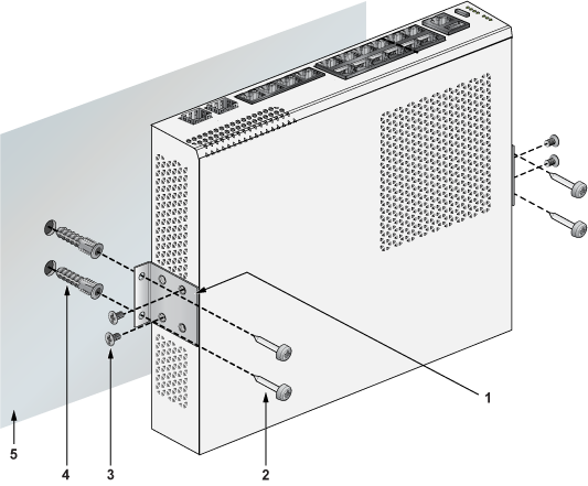
L-Bracket Wall Mount (Default)
This section provides instructions for wall mounting the switch using L-Bracket.
|
1 |
L-Bracket |
|
2 |
Screw M4x25mm |
|
3 |
Flat head screw M4x6mm |
|
4 |
Screw anchor M4 |
|
5 |
Flat surface wall |
- Position the L-Bracket aligning with the chassis holes on the side of the switch and fix it with M4x6mm flat head screws. The L-Bracket is attached to the chassis.
- Attach the remaining L-Bracket on the other side of the chassis and fix it with M4x6mm flat head screws.
- Determine the mounting position to attach the switch to the wall.
- Drill four holes (two on each side) 7x25mm deep on the wall. Refer to the L-Bracket for detailed hole locations.
- Insert M4 screw anchor to the four holes drilled on the wall.
- Place the chassis, attached with L-Bracket, on the wall aligning with the mounting holes and secure the device with M4x25mm screws.
- Tighten the screws to fix the device firmly to the wall.
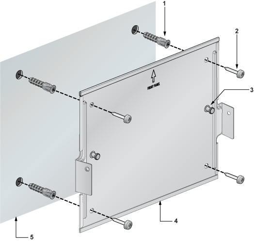
3-in-1 Bracket Wall Mount (Optional)
This section provides instructions for wall mounting the switch using a 3-in-1 mounting bracket.
|
1 |
Screw anchor M4 |
|
2 |
Screw M4x25mm |
|
3 |
Cross hole stud |
|
4 |
3-in-1 bracket |
|
5 |
Flat surface wall |
|
1 |
Chassis |
|
2 |
Cross hole |
|
3 |
3-in-1 bracket |
|
4 |
Flat head screw M4x6mm |
|
5 |
Flat surface wall |
|
6 |
Flat head screw M4x6mm |
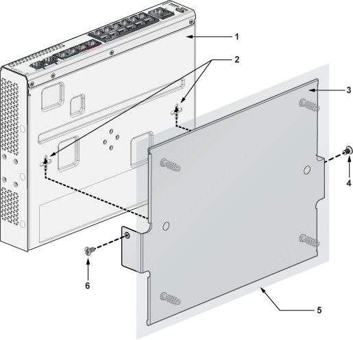
- Align 3-in-1 bracket holes with the switch properly as shown in the below image.
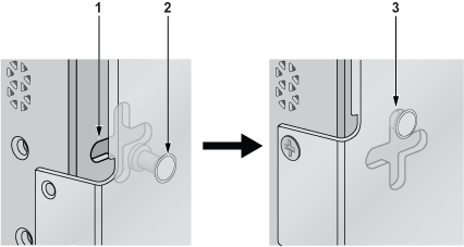
1
Cross hole
2
Cross hole stud
3
Aligning stud to the cross hole
- Place the PSU adapter bracket on the PSU and fix with cable ties around it.
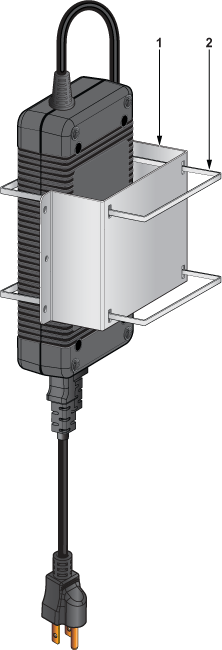
1
PSU adapter bracket
2
Cable ties
- Place the PSU adapter bracket on the wall and mark the mounting holes on the four corners aligning with the mounting bracket.
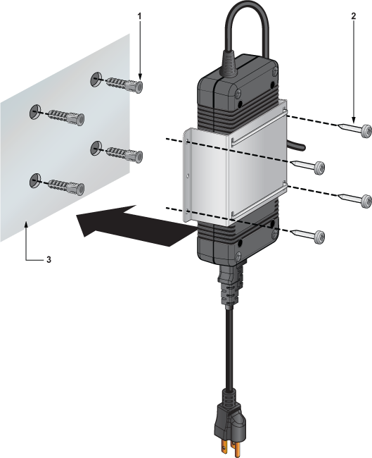
1
Screw anchor M4
2
Screw M4x25mm
3
Flat surface wall
Under Table Mount
This section provides instructions for mounting the switch under the table/desk.
L-Bracket Under Table Mount (Default)
This section provides instructions for mounting the switch under the table/desk using L-Bracket.
|
1 |
Flat wooden table |
|
2 |
L-Bracket |
|
3 |
Flat head screw M4x6mm |
|
4 |
Screw M4x25mm |
- Position the L-Bracket aligning with the chassis holes on the side of the switch and fix it with M4x6mm flat head screws. The L-Bracket is attached to the chassis.
- Attach the remaining L-Bracket on the other side of the chassis and fix it with M4x6mm flat head screws.
- Determine the mounting position to attach the switch under the table.
- Place the chassis, attached with L-Bracket, under the table and secure the device with M4x25mm screws.
- Tighten the screws to fix the device firmly under the table.
3-in-1 Bracket Under Table Mount (Optional)
This section provides instructions for mounting the switch under the table/desk using 3-in-1 mounting bracket.
|
1 |
Flat wooden table |
|
2 |
Screw hole |
|
3 |
Screw anchor M4 |
|
4 |
3-in-1 bracket |
|
5 |
Screw M4x25mm |
|
6 |
Switch |
|
1 |
Flat wooden table |
|
2 |
Cross hole |
|
3 |
3-in-1 bracket |
|
4 |
Flat head screw M4x6mm |
- Determine the mounting position to attach the switch under the table.
- Place the 3-in-1 bracket under the table and mark the mounting holes on the four corners aligning with holes on the 3-in-1 mounting bracket. Figure 5
- Fix the 3-in-1 bracket under the table using the M4x25mm screws on the four corners.
- Attach the switch to the 3-in-1 bracket by aligning with the chassis holes.
- Tighten the screws to fix the device firmly under the table.
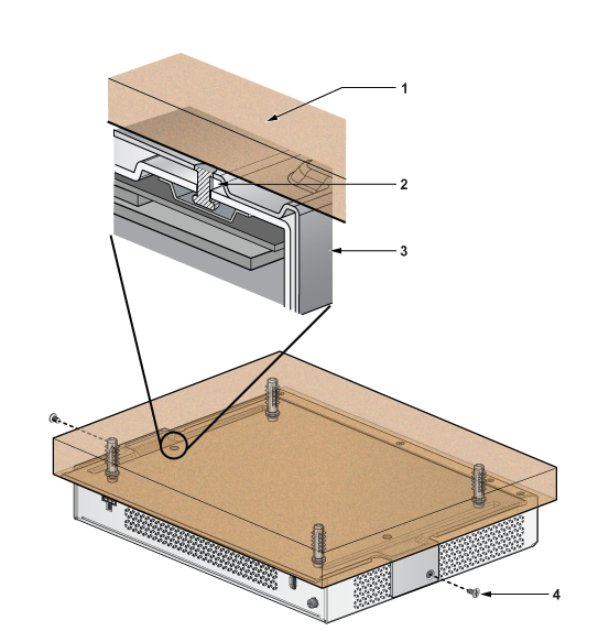
Desktop Mount (Default)
This section provides instructions for mounting the switch on the desktop or any flat surface.
|
1 |
Rubber feet |
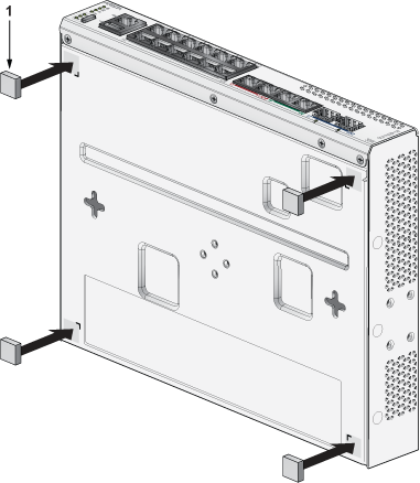
Magnetic Mount (Optional)
This section provides instructions for magnetic mounting the switch. Magnetic mounting is applicable to mount only on metal surfaces.
|
1 |
Rubber Magnet |
|
2 |
3-in-1 bracket |
|
3 |
Switch facing downwards |
|
4 |
Cross hole |
|
5 |
Flat head screw M4x6mm |
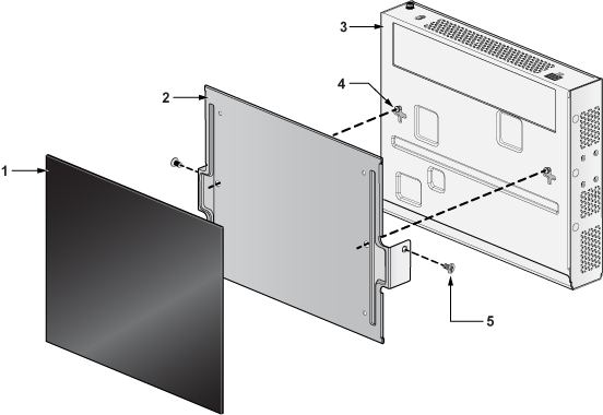
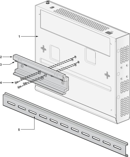
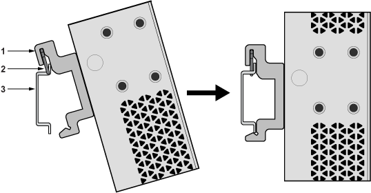
DIN Rail Mount (Optional)
This section provides instructions for mounting the switch using DIN rail.
|
1 |
Chassis |
|
2 |
DIN mount bracket |
|
3 |
DIN rail hook |
|
4 |
Flat head screw M4x6mm |
|
5 |
DIN rail |
- Attach the DIN rail to the mounting bracket with the help of DIN rail hook as shown in the below image.
1
DIN mount bracket
2
DIN rail hook
3
DIN rail holder
- Place the PSU adapter bracket on the PSU and fix with cable ties around it.
1
PSU adapter bracket
2
Cable ties
- Position the PSU adapter bracket on the DIN mount bracket by aligning with the screw holes and fix it with M4x8mm thread screws. The PSU is attached to the DIN rail.
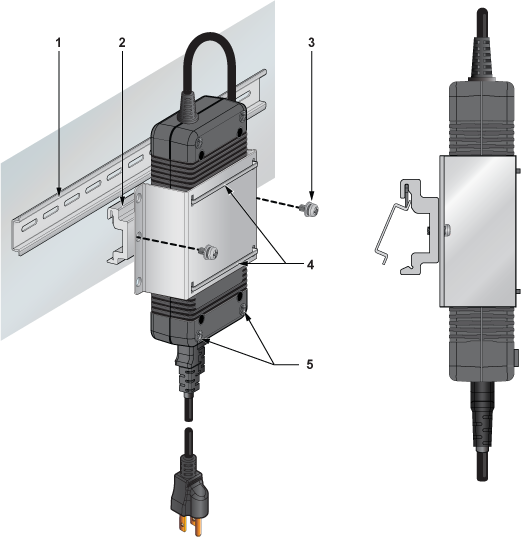
1
DIN rail
2
DIN mount bracket
3
Thread screw M4x8mm
4
Cable ties
5
PSU rubber pads
1RU Rack Mount (Optional)
This section provides instructions for rack mounting the switch.
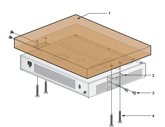
Attaching Mounting Brackets to the Chassis
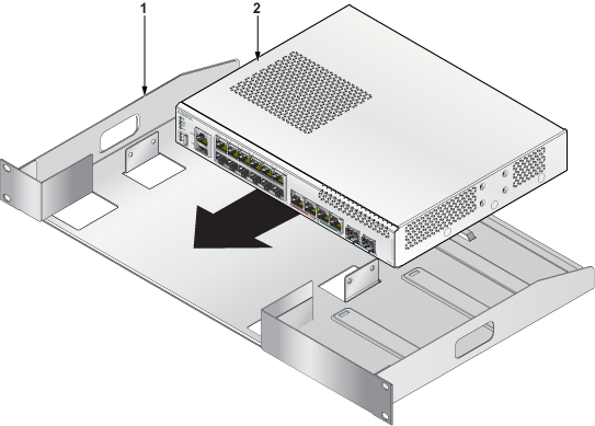
|
1 |
Rack |
|
2 |
Switch |
- Align the rack mounting brackets with the chassis holes at the front of the switch.
- Secure the mounting brackets using the screws provided in the rack mounting kit.
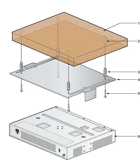
Inserting the Switch into the Rack
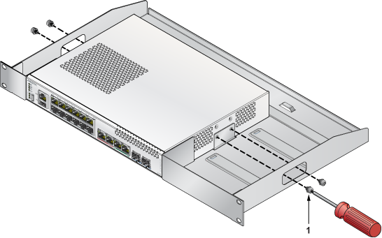
|
1 |
Thread screw M4x6mm |
- Insert the power adapter in the adapter bracket located next to the switch.
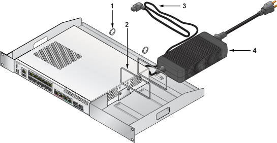
1
Cable ring
2
Cable ties
3
Power adapter cable
4
Power adapter
- Connect the power adapter to the switch as shown in the below image.
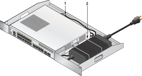
1
Cable ring
2
Cable ties
- Position the rack against the rack posts and mount the rack to the equipment rack.
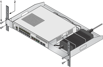
1
Screw M4x8mm
2
Rack posts