Installing the Access Point
This section contains the procedure to install the access point (AP).
Zero-Configuration of the Access Point
- The device must be in AP mode with background scanning on and without a configured SSID.
- Set up a DNS entry forwifi-security-server on all the DNS servers. This entry should point to the IP address of the server. By default, the AP looks for the DNS entry, wifi-security-server.
- Place the AP on a DHCP-enabled subnet.
Assign a static IP address to the AP or change the settings to DHCP. Make a note of the AP MAC address and the IP address in a safe place before installing it in a hard-to-reach location. Locate the AP MAC address on a label at the bottom of the product.
Ceiling Mounting the Access Point
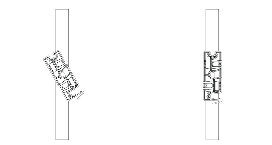
- Attach the bracket to the T-grid - Use the mounting bracket to install the AP on the ceiling. Attach the bracket to the T-grid and rotate the bracket so that it snaps on the T-grid. The bracket becomes parallel to an arm of the T-grid. Be sure the bracket properly snaps to the T-grid, as shown below.
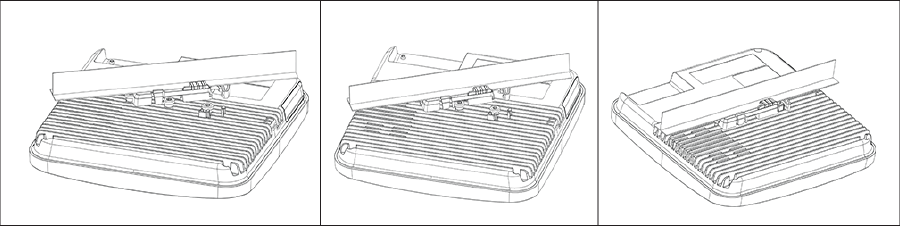
- Mounting C-360 on the bracket - Place the first mounting post on the back of the AP to the lower notch of the bracket. Rotate the AP so that the center mounting post fits in to the center notch on the bracket. Be sure all the mounting posts on the back of the AP snap to the respective notches on the bracket. The mounting posts now properly fit in the respective notches of the bracket and the AP mounts properly.
Mounting Instructions using the Silhouette/Interlude Bracket Mount: The Silhouette/Interlude mounting bracket does not ship as part of the standard package and must be procured separately. The Silhouette/Interlude Bracket mounting instructions contain instructions similar to the Standard Package Content instructions.
Wall Mounting the Access Point
For instructions on wall mounting the access point, refer to the Wall Mount the Access Point article.
Powering the Access Point On
Power the access point (AP) on by plugging one end of the Ethernet cable into the Power over Ethernet (PoE) switch or injector and the other end into the Ethernet/PoE port on the AP. Be sure to turn on the PoE source.
As an alternative to PoE, you can insert a compatible power adapter plug into an AC power outlet and the other end into the power input port on the AP.
Using the C-360 with Power Adapter
- Plug one end of the power cable into the DC power receptacle on the back ofthe device.
- Plug the other end of the power cable into a 110V~240V 50/60 Hz AC power source.
- Wait until the device becomes ready. Refer to the LED status table.
Connecting the Access Point to the Network
- Be sure to install the AP on a DHCP-enabled server on the network.
- Set up a DNS entry for wifi-security-server on all DNS servers. This entry must point to the IP address of the server. This entry should point to the server IP address. By default, the AP looks for the DNS entry, wifi-security-server.
- Verify the AP LED status as ON with green LEDs, indicating an operational AP connected to the server.
- Log on to the server using SSH and run the get sensor list command..
The command returns a list of all Arista devices recognized by the server. Single Sign-On users can go to the Monitor tab in CloudVision WiFi and check if the device appears on the Access Points tab.
If you do not have DHCP enabled on a subnet, the AP cannot connect to that subnet with zero-configuration. If no DNS entry exists on the DNS servers, or if you do not have a DHCP server running on the subnet, you must manually configure the AP. For details on configuring an AP manually, refer to the Access Point Configuration Guide.
Connecting the Access Point using PoE
If using a PoE injector, be sure to plug the data connection into a suitable switch port with proper network connectivity.
For PoE port details, see the Rear Panel section.