Monitor Wired Devices
You can access the switch listing page from .
The Wired page displays the list of discovered switches, managed switches, and hosts. There is no separate configuration needed to display the list of switches. APs collect and analyze the Link Layer Discovery Protocol (LLDP) packets to obtain switch information. The data is then displayed on the UI.
Discovered Switches
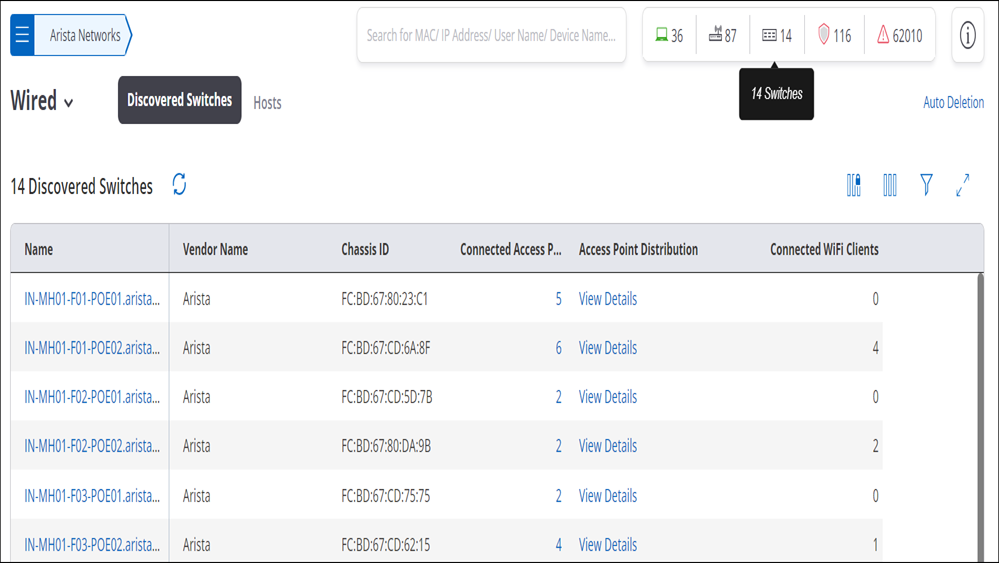
Discovered Switches are switches discovered by Arista’s Managed APs.
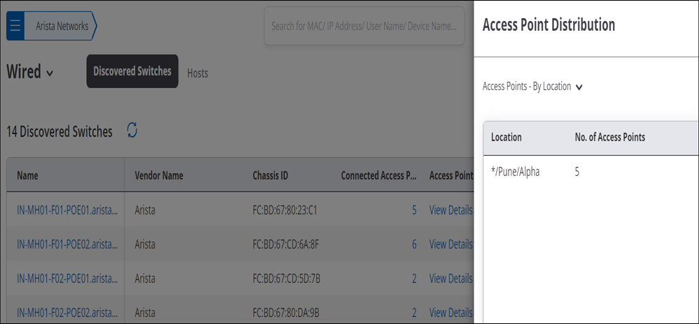
The Discovered Switch listing page displays the vendor name, number of APs managed by that switch, the AP distribution, and the number of connected WiFi clients. The Access Point Distribution column has a link to view all the APs connected to the switch. Since the APs are tied to the location hierarchy, if you do not have access to a particular location, you may not see the APs managed by the switch.
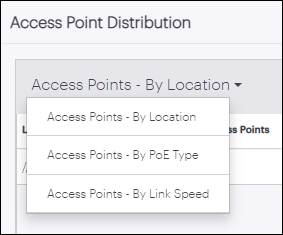
- The categories for PoE Type are PoE, PoE+, andPoE++.
- The categories for link speed are 10Gbps, 5Gbps, 2.5Gbps, 1Gbps, 100Mbps, and 10Mbps.
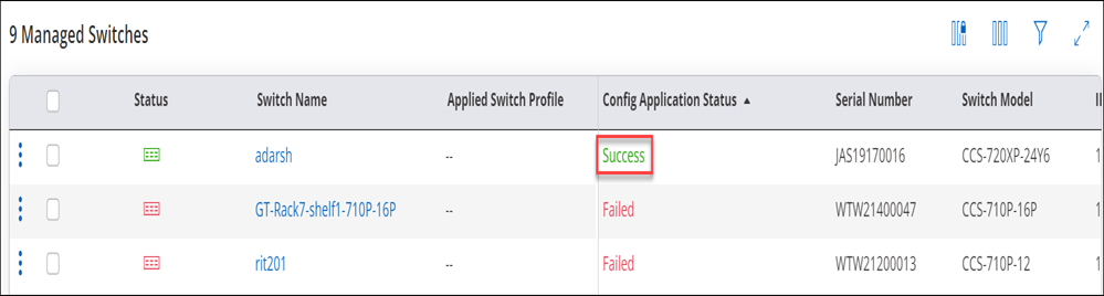
Managed Switches
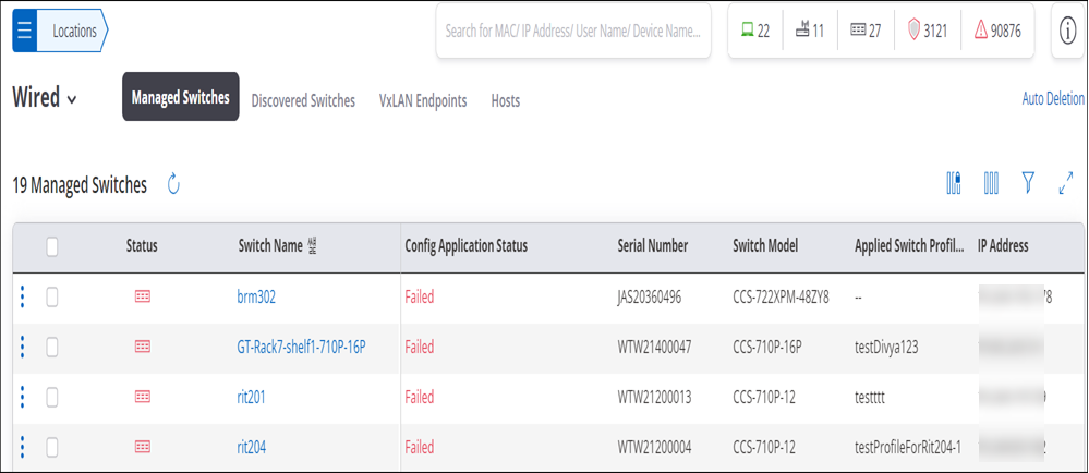
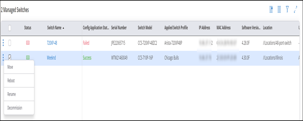
The Managed Switches listing shows all the managed switches deployed in your network. You will see the Manged Switches tab if you have enabled CVaaS.
CV-CUE displays the switch details for the following switch models — 710P, 720XP, 720D, and 722XP. It contains information about the switch such as Software Version, MAC Address, Location, Status, Total Ports, Available Ports, Available PoE Power, etc.
You can perform the following operations on Managed switches:
-
Move: Move to switch to a different location.
-
Rename: Rename the switch.
-
Decommission : You can decommission a switch and remove it from CV-CUE. Once you decommission a switch, it is deleted from CV-CUE and you need to onboard the switch again.
-
Reboot: Reboot the switch.
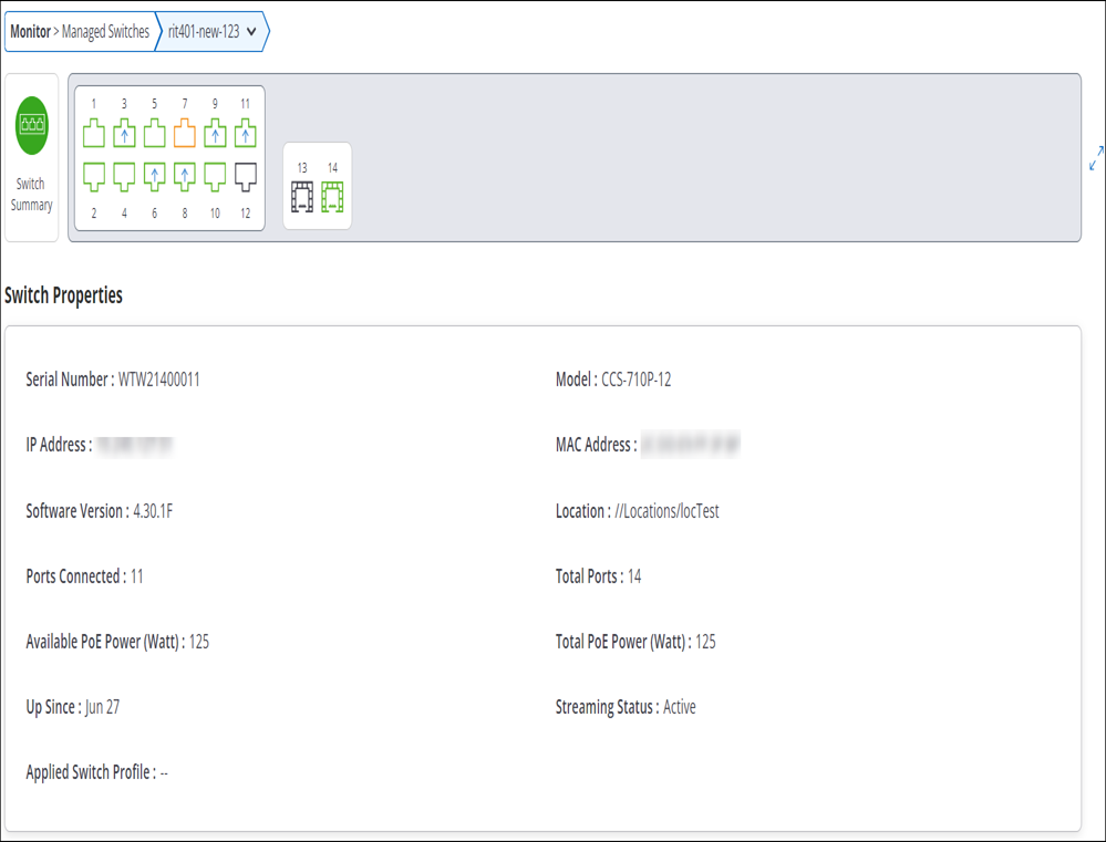
Switch Details
Click the switch name to view complete details of the switch. Switch details contain Switch Summary, Switch Properties and Switch Layout, Switch Topology. Hover over a port in the Switch layout to view its status. You can also click a particular port to view more details about the port. To go back to summary, click the Switch Summary icon.
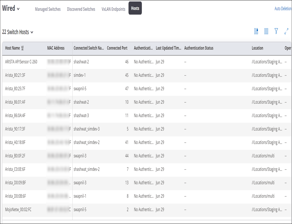
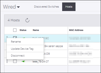
Hosts
Host tabs contain information about devices connected to switches.
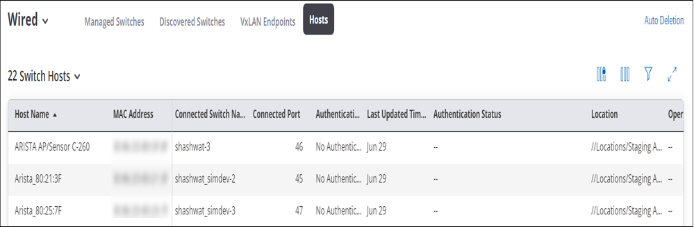
Monitor Wired Hosts
You can monitor hosts or clients connected to the wired ports from .
Onboard Switches
You can onboard switches manually or use Arista’s Zero Touch Provisioning (ZTP) to onboard your switches to CV-CUE.
Onboarding Switches using ZTP
You can use ZTP to onboard a switch without user intervention. ZTP leverages the power of Arista’s Extensible Operating System (EOS) to onboard switches.
Prerequisites:
- DHCP Server: Switch should be able to reach arista.io by obtaining valid IP settings from a DHCP server.
- EOS Version: The device should be running EOS version 4.25.5 or 4.26.1 or newer.
You can enable ZTP using a custom bootstrap script and use a DHCP server option to point to that bootstrap script.
To enable ZTP using a bootstrap script:
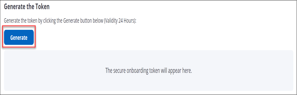
- Log in to the CV-CUE and generate a token from and click Generate.
- Prepare a bootstrap script and host it on an HTTP server. You can get asample script fromhttps://github.com/aristanetworks/cloudvision-ztpaas-utils.
- Provide the updated token information and other information in the bootstrap
script.
############## USER INPUT ############# cvAddr = "www.cv-staging.corp.arista.io" enrollment_token = "eyJhbGciOiJSUzI1Nixxx..." ############## USER INPUT ############# Note: If the device is behind a non-transparent proxy, use the following cvproxy option: # Add proxy url if device is behind proxy server, leave it as an empty string otherwise cvproxy = "" Note: You can start an HTTP server using python (python3 -m http.server 8000 &), and host the bootstrap.py file, and then point the DHCP server to download from this server location. - Host the script on a TFTP server locally and direct the DHCP server to point to the
bootstrap script via option-67/bootfile-name option:
For example:
subnet 10.10.1.1 netmask 255.255.255.0 {
range 10.10.1.1 10.10.1.253;
option domain-name "dev.aristanetworks.com";
option routers 10.10.1.250;
option domain-name-servers 10.10.1.5;
option ntp-servers time.google.com;
host leaf-1A {
hardware ethernet fc:bd:67:aa:22:33;
fixed-address 10.10.1.180;
option host-name "leaf-1A";
option bootfile-name "http://10.10.1.10:8000/bootstrap.py";
}
Note: Make sure the ntp-servers option is set in your DHCP configuration. - Boot up the switch into ZTP provisioning mode.
The onboarding process begins and the successfully onboarded switches are displayed under tab.
Note: You can use the same bootstrap script and token to onboard multiple switches. Ensure that the token has not expired before proceeding.
Onboarding Switches Manually
You can onboard switches manually to CV-CUE. The onboarded switches show up as Managed Switches in CV-CUE.
To onboard switches manually:
- Go to
- Click Switch Onboarding.
- Follow the instructions shown.
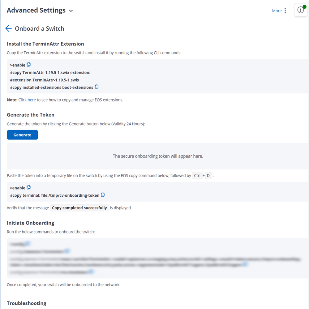
Note: You can use the same token to onboard multiple switches in one go.
Onboarded switches are available under tab.All the managed switches when first identified are deployed in the staging environment.
Configure Switches
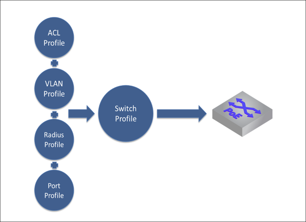
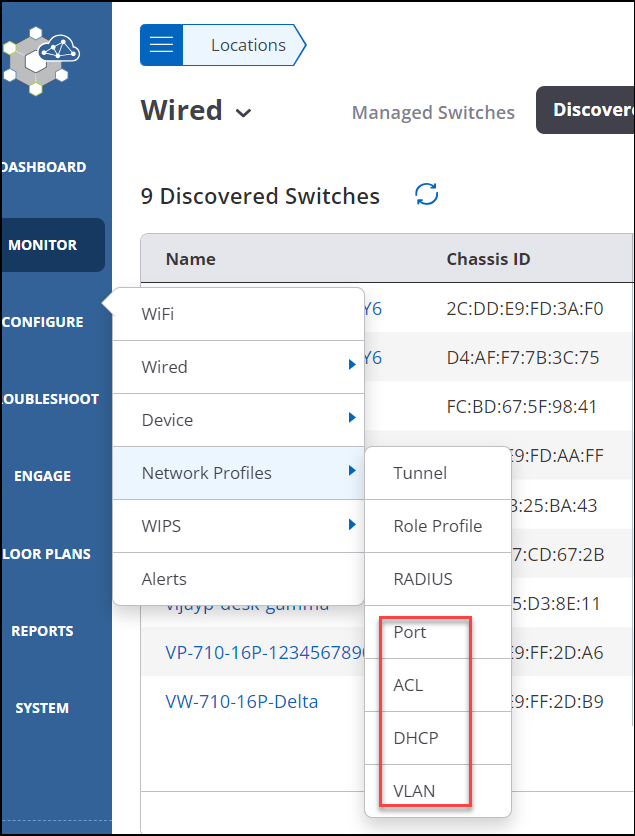
Create Network Profiles
To configure a switch, you need to create the following network profiles:
-
You can create network profiles by navigating to
Port Profile
With Port Profile, you can configure all the settings of a switch port.
To create a Port Profile:
- Go to
- Click Add Switch Port Profile.
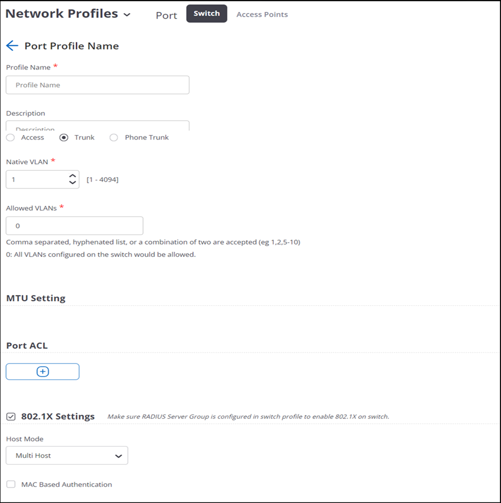
- Provide the port profile name and description.
- Select Enable PoE and select the power mode.
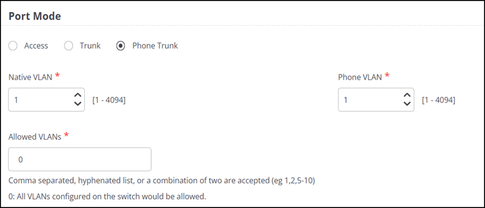
- Select the Port Mode. You can select:
- Access Mode: Provide the access VLAN.
- Trunk Mode: Trunk mode allows you to connect multiple VLANs. Provide the Native VLANs and Allowed VLANS.
- Phone Mode: Phone mode allows you to connect a phone. Along with
Native VLAN and Allowed VLANs, provide the Phone
VLAN. You can also set the phone traffic as tagged or untagged.
- Select the MTU Settings.
- Enable Port Security to define the maximum number of MAC Addresses. You can also select the action to take if the MAC Addresses exceed the allowed value.
- Click Add Port ACL to add and define ACL Profile for this port.
- Select 802.1X Settings to apply RADIUS Group Configuration to this port.
- Click Save.
ACL Profile
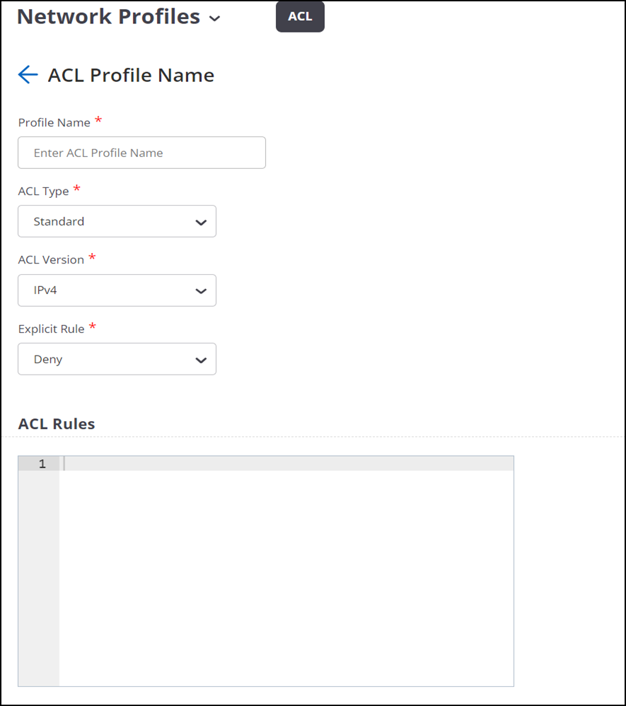
To create an ACL Profile:
- Go to
- Click Add ACL Profile.
- Select the ACL Type:
- Standard
- Extended: Along with the source and destination address, you can provide the protocol as well.
- MAC
- Select either IPv4 or IPv6 as ACL Version.
- Select either Permit or Deny for the Explicit Rule. An explicit rule is applied if none of your defined ACL rules are applicable.
- Provide the ACL Rules. For example, permit host 1.1.1.1
You can also check the rule syntax.
- Click Save.
DHCP Profile
WithDHCP Profile, you can configure DHCP server for a particular VLAN on the switch.
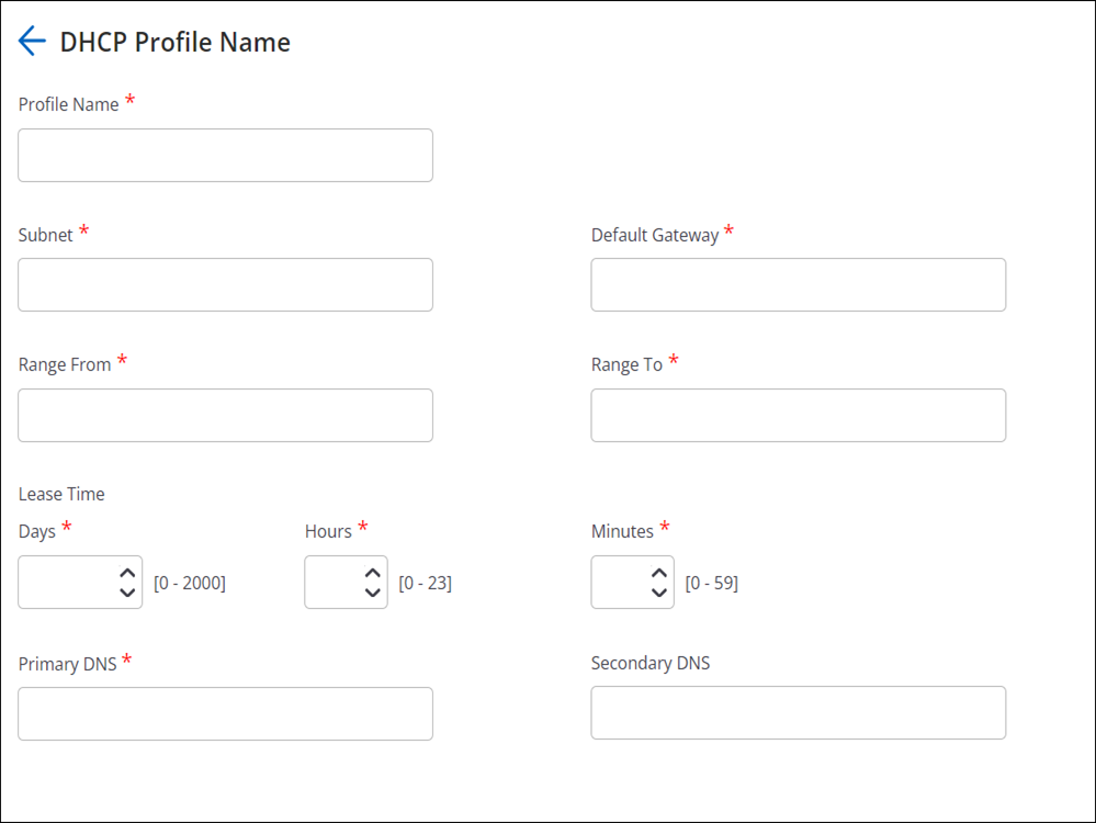
- Go to
- Click Add DHCP Profile.
- Provide the Profile Name, Subnet, and Default Gateway of the DHCP server. The IPv4 address for the subnet has to be in the CIDR notation. For example, 192.168.100.1/24.
- Provide the DHCP Range and define the Lease Time.
- Provide the Primary DNS and Secondary DNS.
- Click Save.
VLAN Profile
With VLAN Profile, you can configure VLAN and virtual interface. One VLAN profile corresponds to one VLAN.
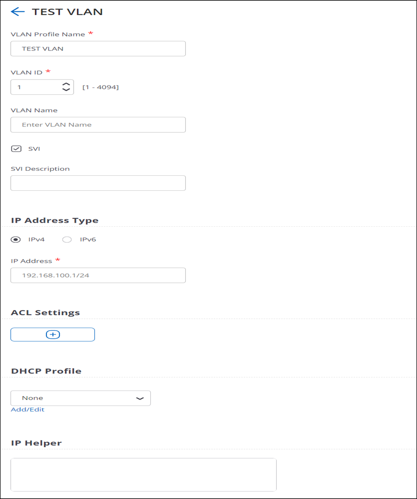
- Go to
- Click Add VLAN Profile.
- Provide the Profile Name, VLAN ID, and VLAN Name.
- Select SVI to enable the virtual interface.
- Provide the following details for SVI:
- IP Address Type
- IP Address
- IP Helper
- ACL Profile
- DHCP Profile
- Click Save.
Create Switch Profiles
Switch profile consists of switch configuration, RADIUS server settings, mapping switch ports to port profile, and SNMP server details.
To create a switch profile:
- Navigate to
- Click Add Switch Profile.
- Provide the switch name.
- Select Enable LLDP and Enable STP.
- Select the VLAN Profile.
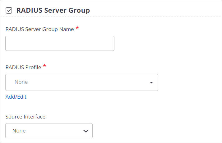
- Select Enable RADIUS Server Group to enable RADIUS server. Select the source
interface to use to communicate with the RADIUS server and provide the interface
number.
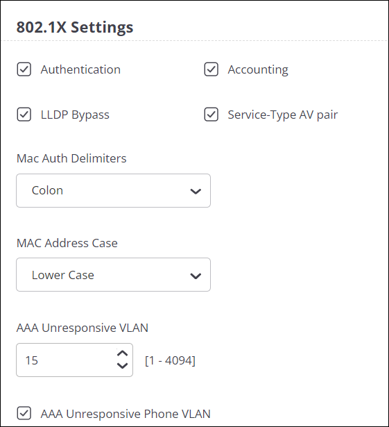
- Specify the 802.1X Settings. You can also specify the Unresponsive VLAN to
use if the RADIUS server is unresponsive.
- Select the ACL Profile.
- Select Enable IGMP Snooping and select the IGMP version.
- Provide Static Route Configuration. Static routes are typically used when dynamic protocols are unable to establish routes to a specified destination prefix. Static routes are also useful when dynamic routing protocols are not available or appropriate.
- Select DHCP Relay and provide the DHCP server IP address.
- Click + under the Mapping Switch Ports to Port Profile section.
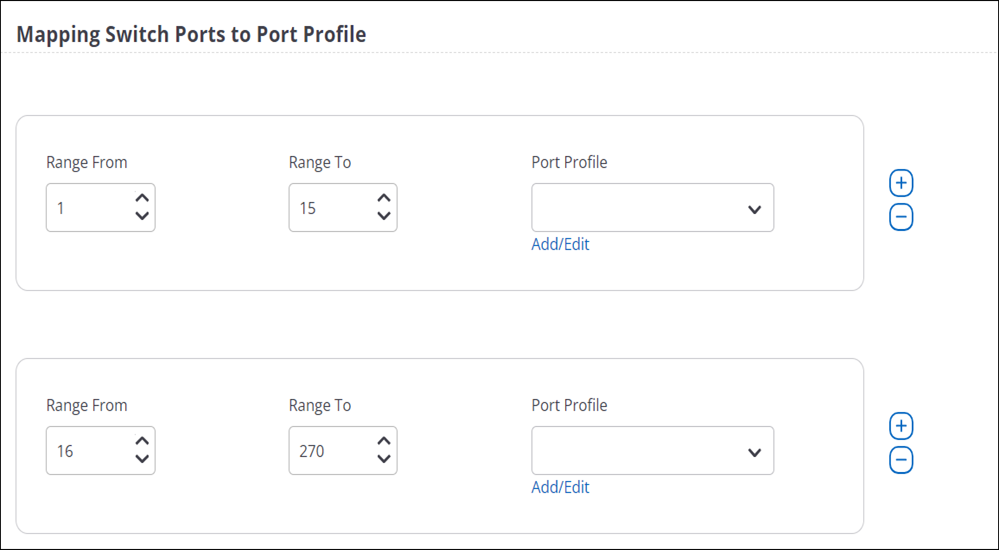
- Provide port ranges and select the port profile to apply to that entire port range.
Ensure that port values do not overlap. A port can have only one port profile mapped
to it. Note:
Provide the same port value number in the From and To field to map a port profile to a single port.
- Click + under SNMP Servers to send information to the SNMP server using SNMP Traps.
- Click Save.
Apply Switch Profile to a Switch
You can apply only one switch profile per switch.
To apply a switch profile to a switch:
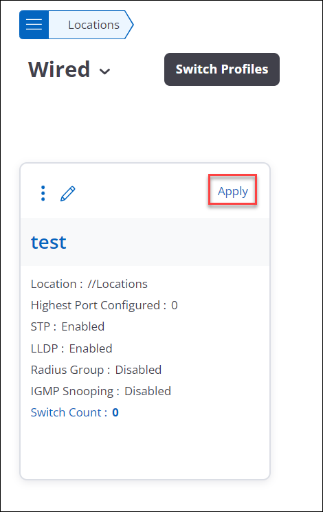
- Navigate to
- Select the profile to apply and click Apply.
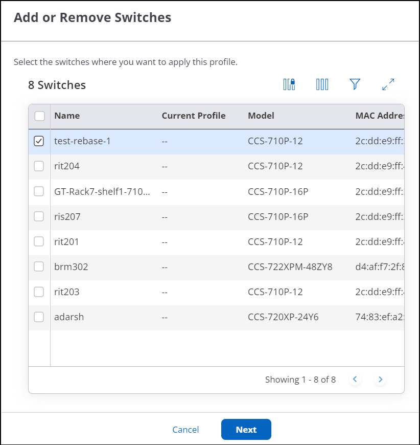
-
The switch pane opens and displays all the available switches. Switches that already have this profile are preselected. You can uncheck the selection to remove the profile from those switches. Select the switches that you want to apply the profile to and click Next.
- Verify the switches where the profile will be applied. If you have unchecked a
switch in the previous pane, confirm that the switch doesn’t appear here. Click
Apply.
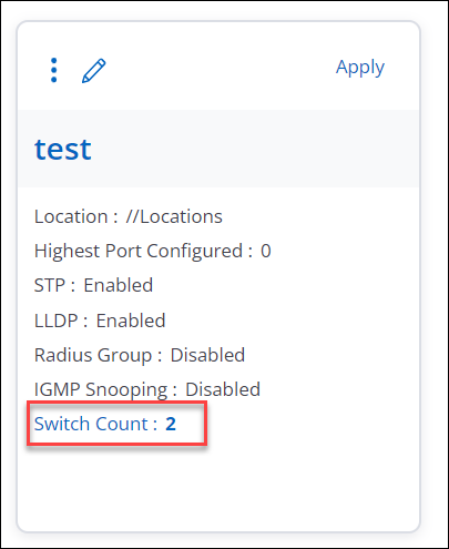
The switch profile card shows the total number of switches using the particular profile.
Configure Device Settings
Switch device settings are divided into two tabs:
- General
- Security
General Switch Settings
To configure general switch settings:
- Navigate to
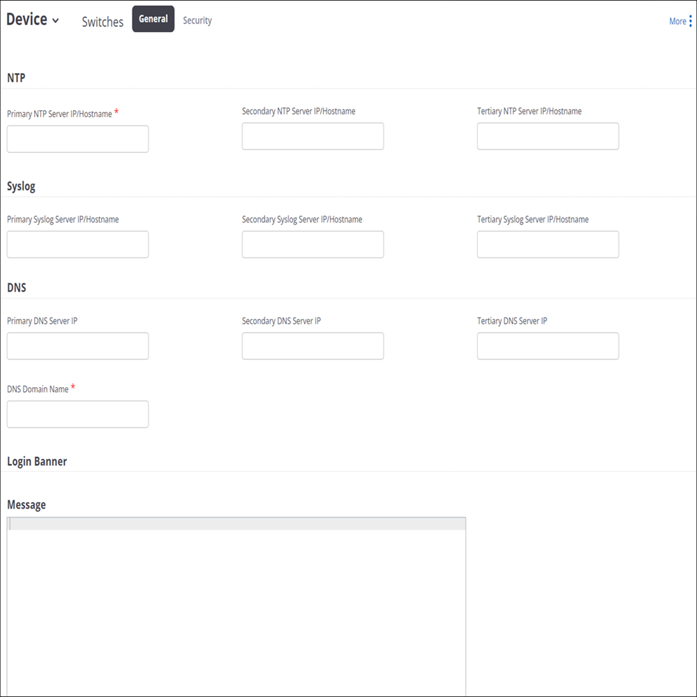
- Under the General tab, provide the following details:
- NTP - Provide details of the NTP server to ensure that the timestamp on the logs reflects the correct date and time by synchronizing the Arista device system clock with an NTP server.
- Syslog - Provide details of the Syslog server to send messages and alerts to the Syslog server.
- DNS - Provide details of the DNS server to fetch the DNS information.
- Login Banner - Provide a text message to display on the switch CLI.
- Click Save.
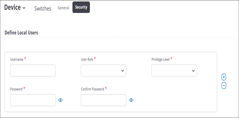
Security Settings
VXLAN Endpoints
VXLAN tunneling requires that the switch where the tunnel terminates is configured with a VTEP that matches the configuration on the AP.By having the same VXLAN configuration for APs and switches, you can aggregate all wireless traffic from the same VXLAN to a single wired destination for better traffic management and visibility.
To configure the switches from CV-CUE, the first step is to import the switches to the VXLAN Endpoints tab. You can import one switch at a time and up to a maximum of 10 switches to CV-CUE. Only those switches that you import, get listed in the VXLAN Profile.
- Go to .
- Click Import VXLAN Switch.
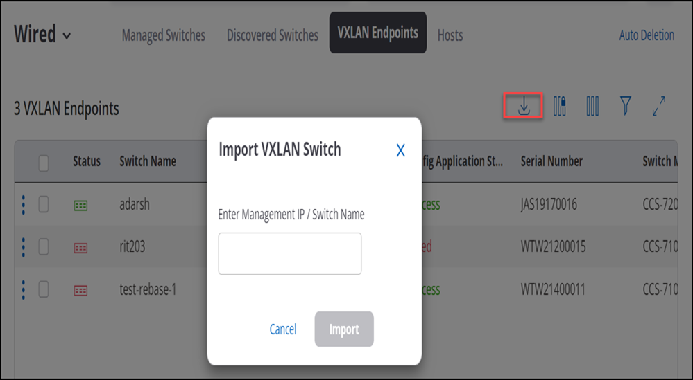
- Provide the Management IP address of the switch or the name of the switch and click Import.
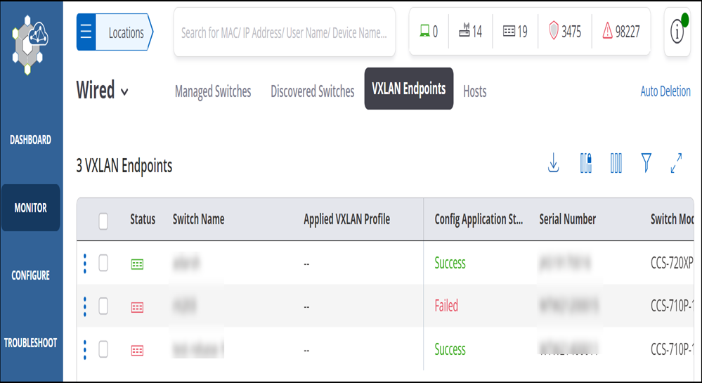
Once imported, you can delete the switch listing from the page, rename switches, and reboot switches. You can rename and reboot active switches.