Tunnel Interface
A Tunnel Interface is used to route network traffic on an SSID to and from a single aggregation point or endpoint. For instance, a distributed enterprise can channel Wi-Fi traffic from remote locations to the enterprise HQ for inspection, applying policies, and regulatory compliance.
- EoGRE: Ethernet over GRE. See EoGRE for details.
- EoGRE over IPsec: Ethernet over GRE over IPsec where Ethernet frames are encapsulated using GRE and then encrypted using IPsec. See EoGRE over IPsec for details.
- VXLAN (Virtual Extensible LAN): Virtual Extensible LAN (VXLAN) was originally developed to overcome the limited scalability of VLANs in large network deployments such as datacenters. See VXLAN for details.
- VxLAN over IPSec: VXLAN creates a virtual network and IPSec adds a layer of security to the SSID traffic using different encryption methods.
- What is EoGRE?
- What is EoGRE over IPsec?
- What is VXLAN?
- What is VXLAN over IPSec?
- Configure Tunnel Interface
- Tunnel Interface Parameters
- Configure an IPSec Tunnel
- Configure an IPSec Tunnel with EAP-TLS Authentication
- How Failover Works in a Tunneled Network
- Configure VXLAN Profile for Wired-Wireless Tunnel
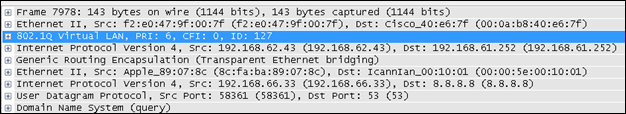
What is EoGRE?
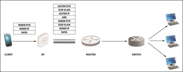
- Inner Eth – source: client MAC/destination: gateway MAC address.
- Inner IP – source: client IP/destination: IP of the destination the client is trying to reach Data.
- SSID VLAN (optional) – If a VLAN ID is configured in the SSID, then it is appended to the packet.
- GRE – All flags set to 0; Ether-Type set to 0x6558 for native Ethernet
- Outer IP source – IP of the AP/IP of the tunnel end-point
- N/W VLAN (optional) – If a VLAN is configured for the tunnel, then it is appended to the packet.
- Outer Eth source – AP MAC/destination: MAC of the next hop.
What is EoGRE over IPsec?
EoGRE over IPSec is a method of providing security to the Ethernet packets traversing a GRE tunnel. GRE encapsulates the data packets, while IPSec ensures the security of such encapsulated data packets by using different encryption methods. Using IPSec, an extra layer of security is added to the GRE packets in order to protect client’s sensitive information against eavesdropping or any modification. GRE packets are secured in two phases:
Using IPSec, an extra layer of security is added to the GRE packets in order to protect client’s sensitive information against eavesdropping or any modification.
- Phase I: This phase describes different security mechanisms used to authenticate and validate the keys that are shared between the endpoints.
- Phase II: This phase describes different methods to encrypt the payload of the packet, to provide a high level of privacy, confidentiality, and security from spoofing or any possible threat of tampering.
Default Cipher Combination for a Better Throughput
- Aes-128-sha1-modp1024
- Aes-128-sha2_256-modp1024
- Aes-256-sha1-modp1024
- Aes-256-sha2_256-modp1024
What is VXLAN?
VXLAN was developed to overcome the limited scalability of VLANs in large network deployments, e.g., datacenter networks. VXLAN creates a virtual network on top of a physical network. The virtual network is called an "overlay" while the physical network infrastructure it runs on is called an "underlay." Switches and routers that participate in VXLAN have a special interface called a VTEP. The VTEP provides the connection between the underlay and the overlay. The ethernet frames traveling over the VXLAN tunnel are encapsulated in IP and UDP headers at the source host and decapsulated at the destination client.
Arista switches support VXLAN to enable scalable virtualized datacenter networking. In addition, Arista Wi-Fi Access Points (APs) also support VXLAN to allow tunneling of data from Wi-Fi APs to a central aggregation point, e.g., an Arista switch. This allows enterprises to migrate their existing controller-based Wi-Fi networks to Arista's controller-less cloud architecture without having to change the design of their underlying campus network.
What is VXLAN over IPSec?
VXLAN was developed to overcome the limited scalability of VLANs in large network deployments, e.g., datacenter networks. VXLAN creates a virtual network on top of a physical network. The Ethernet frames traveling over the VXLAN tunnel are encapsulated in IP and UDP headers at the source host and decapsulated at the remote endpoint.
VXLAN creates a virtual network and IPSec adds a layer of security to the SSID traffic using different encryption methods. Using IPSec, an extra layer of security is added to the VXLAN packets in order to protect client’s sensitive information against eavesdropping or any modification.
Configure Tunnel Interface
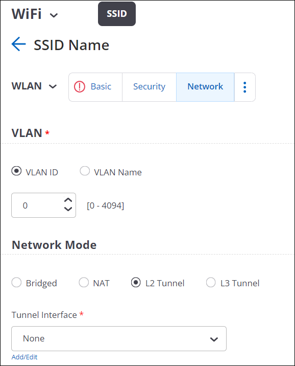
A Tunnel Interface represents the tunnel through which network traffic from the configured SSIDs can be routed to a remote endpoint. You can configure various L2 and L3 tunnels depending on your business need.
- EoGRE (L2 Tunnel)
- EoGRE over IPSec (L2 Tunnel)
- VXLAN (L2 Tunnel)
- VXLAN over IPSec (L2 Tunnel)
- VPN with IPSec (L3 Tunnel)
- Navigate to
- Click Add Tunnel Interface.
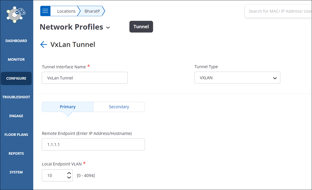
- Provide a name for the tunnel interface and select the Tunnel
Type as VXLAN.
- Select L2 Proxy to have the Access Points (APs)act as L2 Proxy for
clients connected to SSIDs that have VXLAN tunnels configured. With L2 Proxy
enabled, the Switch or the VTEP doesn’t receive the actual MAC address of
the client; instead, it receives the MAC address of the AP and interacts
with the AP.
The AP maintains a table of the client MAC addresses. When the AP receives a frame from the client, it replaces the client MAC address with its uplink port MAC address and forwards the client frame to the VTEP. Packets from the Gateway Switch destined for the clients are delivered to APs MAC address. The AP compares the client IP-MAC address table to rewrite the destination MAC address before sending it to the client.
Note:The secondary tunnel is disabled when you select L2 Proxy. Even if you have configured a secondary tunnel, on enabling L2 Proxy, the secondary becomes unavailable.
Inter AP Coordination over a tunnel is disabled when L2 Proxy is enabled. The AP shares its client details to its RF neighbors (neighboring APs). When a client roams to a different AP, the AP initiates an ARP/GARP request with the Gateway Switch to update the Gateway’s table with the new client address.
- Configure the primary endpoint.
- Remote Endpoint: Provide the IP address or the hostname of the remote endpoint where the tunnel terminates.
- Local Endpoint VLAN: VLAN ID of the local endpoint. This is the VLAN ID from where the tunnel is formed.
- VXLAN VNI Offset: Enter the offset number for the remote endpoint VNI. An offset is the difference between the Switch VNI (typically the remote endpoint) and the local endpoint VLAN. For example, if the Switch VNI is 10000 and the local endpoint VLAN is 998, then the VXLAN VNI Offset is 9002 (Switch VNI - Local Endpoint VLAN = VXLAN VNI Offset).
- (Optional) Configure a secondary endpoint.
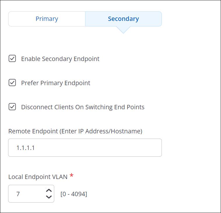
- Enable Secondary Endpoint: Select this check box to make the secondary endpoint active when the primary endpoint is not reachable. See How Failover Works in a Tunneled Network to know more about switching between primary and secondary endpoints.
- Prefer Primary Endpoint: Select this check box if you want to revert to the primary endpoint whenever it is available.
- Disconnect Client on Switching Endpoints: The connected clients losses their connectivity whenever the tunnel endpoint changes between primary and secondary.
- Remote Endpoint: Provide the IP address or the hostname of the remote endpoint where the tunnel terminates.
- Local Endpoint VLAN: VLAN ID of the local endpoint. This is the VLAN ID from where the tunnel is formed.
- VXLAN VNI Offset: Enter the offset number for the remote endpoint VNI. An offset is the difference between the Switch VNI (typically the remote endpoint) and the local endpoint VLAN. For example, if the Switch VNI is 10000 and the local endpoint VLAN is 998, then the VXLAN VNI Offset is 9002 (Switch VNI - Local Endpoint VLAN = VXLAN VNI Offset).
- Select Tunnel MTU to configure an MTU value.
- Auto: The AP automatically calculates and applies the MTU value for TCP and UDP packets.
- Manual: Specify the MTU value between 1000 and 1700 bytes for TCP and UDP packets. The default value is 1500 bytes.
- Enforce Fragmentation: When selected, the AP forcefully fragments the UDP packets despite the client enabling the Don't Fragment bit (DF bit). If you don't select this option and the client has enabled the DF bit, then the AP will drop UDP packets that exceed the MTU value. If you select this option, then the AP will automatically fragment larger UDP packets into smaller packets and send them to the remote endpoint.
- Save the tunnel configuration.
Tunnel Interface Parameters
The table below provides information required to configure a Tunnel Interface Profile.
| Field | Description |
|---|---|
| Tunnel Interface Name | Name of the tunnel interface profile. |
| Tunnel Type | Select appropriate network tunnel type: EoGRE, EoGRE over IPSec, VXLAN, or VXLAN over IPSec. |
| Primary Endpoint Parameters | |
| Remote Endpoint (IP/Hostname) | The IP address or hostname of the primary remote server or endpoint. |
| Local Endpoint VLAN | This is the VLAN ID with which the tunneled traffic is tagged. A value between 0 and 4094 should be entered here. |
|
Secondary Endpoint Parameters |
|
| Enable Secondary Endpoint | The secondary endpoint is a remote endpoint to which the wireless traffic is diverted if the primary endpoint goes down. Select this checkbox if you want to enable a secondary endpoint. |
| Remote Endpoint(IP/Hostname) | The IP address or hostname of the secondary remote server or endpoint. |
| Local Endpoint VLAN | This is the secondary VLAN ID that the tunneled traffic is tagged with. A value between 0 and 4094 should be entered here. |
| Prefer Primary Endpoint | Select the checkbox if you want the AP to check for the availability of the primary tunnel. The traffic is bridged to the secondary endpoint if the primary endpoint fails. If this option is checked, the secondary endpoint checks for the availability of the primary endpoint and transfers control back to the primary endpoint once it is up and running. |
|
Retry Parameters (They govern how the AP pings the remote endpoint to check for connectivity) |
|
| Network Probe Interval | The interval, in seconds, after which the AP checks connectivity with remote endpoint by sending a ping request packet. This can have a value between 10 and 3600. The interval must be a multiple of 10. It should be greater than Network Ping Timeout. |
| Network Ping Retry Count | Count of ping request packets that the AP sends to the remote endpoint. The default value is 2. |
| Network Ping Timeout | Time, in seconds, till which the AP waits for a ping reply. The default value is 10 seconds. |
|
Ethernet over GRE Parameters |
|
| GRE Primary Key | This is an optional setting. If configured, the same key should be used at both ends of the tunnel. |
| GRE Secondary Key | This is an optional setting. If configured, the same key should be used at both ends of the tunnel. |
Configure an IPSecTunnel
- Navigate to
- Click Add Tunnel Interface.
- Select the Tunnel Type as EoGRE over IPSec.
- Specify the primary endpoint details such as the remote endpoint, GRE primary key, and Local Endpoint VLAN ID.
- Specify the secondary endpoint details so that APs can communicate with a secondary
remote endpoint when the primary endpoint becomes unreachable. Refer to How the Failover
Works in an IPSec Tunnel to understand how the tunnel switches between primary
and secondary. The following fields are specific to the secondary endpoint configuration:
- Enable Secondary Endpoint: Select this check box to make the secondary endpoint active when the primary endpoint is not reachable. See How Failover Works in a Tunneled Network to know more about switching between primary and secondary endpoints.
- Prefer Primary Endpoint: Select this check box if you want to revert to the primary endpoint whenever it is available.
- Disconnect Client on Switching Endpoints: The connected clients losses their connectivity whenever the tunnel endpoint changes between primary and secondary.
- Click Configure IPSec.
- Select the mode as Tunnel.
- Enter the IP address or the hostname of the remote endpoint of the GRE tunnel.
- Select the Virtual IP address support checkbox. On selecting this field, the remote endpoint assigns a virtual IP address for incoming packets.
- Click Phase 1 Parameter. Phase I Parameter consists of IKE Settings and cipher configuration.
- Specify the Lifetime/IKE keepalive value.
- Internet Key Exchange (IKE) keepalive is the duration (in hours) for which the generated keys are active.
- After the specified time, new keys are generated and get shared between the endpoints.
- Select the authentication method and authentication parameters for Local (Left) and Remote (Right). The available authentication methods are: PSK and EAP. The authentication parameters vary between PSK and EAP.
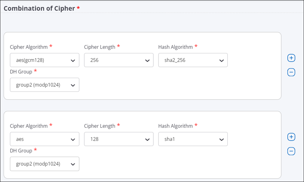
- Select the cipher, hash algorithm, and DH group values.Note: Use one the following combination of ciphers for the maximum throughput. If you use any other cipher combination, your throughput may decrease.
- Aes-128-sha1-modp1024
- Aes-128-sha2_256-modp1024
- Aes-256-sha1-modp1024
- Aes-256-sha2_256-modp1024
- Click Phase 2 Parameter. Phase 2 Parameter has cipher configurations.
- Specify the Lifetime/Phase 2 keepalive value.
- Select ESP (Encapsulating Security Payloads) or AH (Authentication Header) protocol, and then select cipher, hash algorithm, and DH group values.
- Save the IPSec settings.
- Specify the values for Tunnel MTU.
- Auto: The AP automatically calculates and applies the MTU value for TCP and UDP packets.
- Manual: Specify the MTU value between 1000 and 1700 bytes for TCP and UDP packets. The default value is 1500 bytes.
- Enforce Fragmentation: When selected, the AP forcefully fragments the UDP packets despite the client enabling the Don't Fragment bit (DF bit). If you don't select this option and the client has enabled the DF bit, then the AP will drop UDP packets that exceed the MTU value. If you select this option, then the AP will automatically fragment larger UDP packets into smaller packets and send them to the remote endpoint.
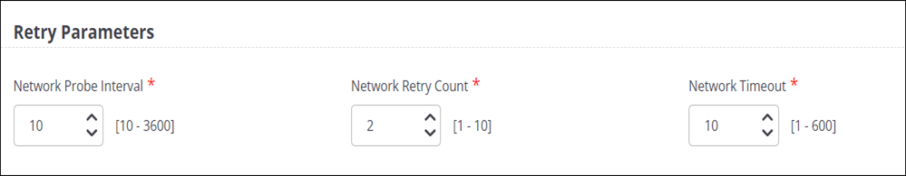
- Configure the Retry Parameters settings.
- Network Probe Interval: The interval, in seconds, after which the AP checks connectivity with the remote endpoint by sending a ping request packet. You can define a value between 5 and 3600. The default value is 5. Also, the value must be greater than the Network Timeout value.
- Network Retry Count: Count of ping requests that the AP sends to the remote endpoint. The default value is 2.
- Network Timeout: Time, in seconds, until which the AP waits for a ping reply. The default value is 5 seconds.
- Save the configuration.
Configure an IPSec Tunnel with EAP-TLS Authentication
Configure IPSec Tunnel for certificate-based authentication.
When you configure an IPsec Tunnel with IKE Version 2, you can configure the Local (Left) to use the certificate-based authentication to form the tunnel with the Remote (Right). It is mandatory for you to upload the CA certificate for the Remote (Right) endpoint.
- Go to .
- Select any IPSec tunnel type. For example, select the Tunnel Type as EoGRE over IPSec.
- Specify the primary and secondary endpoint details.
- Click Configure IPSec.
- Select the Mode as Tunnel and provide the details.
- In the Phase 1 Parameters > IKE Version 2, specify the Local (Left)
settings. The following settings are required for the certificate-based authentication:
- Access Point Authentication Method: EAP
- EAP Method: TLS (eap-tls)
- Select Certificate Tag: Select the certificate tag from the drop-down list.
- AAA Identity: The address of the AAA server (RADIUS).
- (Optional) Upload Certificate: Upload the CA certificate of the RADIUS server, if the certificate issuer is different for AP and RADIUS. The AP needs the certificate of the RADIUS for mutual authentication.
Figure 1. EAP-TLS selection in IPSec configuration 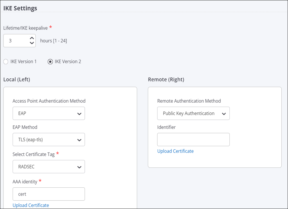
- Specify the Remote (Right) settings. The following settings are required for
the certificate-based authentication:
- Remote Authentication Method: Public Key Authentication
- (Optional) Identifier: The address of the remote endpoint.
- Upload Certificate: Upload the CA certificate of the remote endpoint.
- Keep the default configuration for Cipher settings and Phase 2 Parameter settings.
- Save the configuration.
How Failover Works in a Tunneled Network
In a global organization, most of the communication happens over a tunneled network. To maintain high availability and to report the tunnel health to Access Points (APs), you configure primary and secondary endpoints in a tunnel. AP uses the tunnel health to detect whether the tunnel is down. If the AP can not reach the primary endpoint, it connects with the secondary endpoint and, thus, eliminates the network downtime.
APs use ICMP requests and responses to determine whether the endpoint is reachable or not. An AP that has active clients can suppress ICMP requests, if it receives encapsulated packets from the remote endpoint. If the AP does not have active clients, it may not suppress ICMP requests.
- Network Probe Interval is the time duration between the ping requests. The default value is 10. So, the AP sends the ping 10 seconds apart.
- Network Retry Count is the number of times the AP sends the ping request if it does not receive the response. By default, the AP sends 2 ping requests in total. After each ping is sent, the AP waits for 10 seconds (Network Probe Interval time) and if no response is received, the AP sends the next ping.
- Network Timeout is the time the AP waits to switch the tunnel.
An AP uses these parameters to detect whether the remote endpoint is reachable or not. The AP sends an ICMP request at each network probe interval and waits for the ICMP response from the remote endpoint. If there is no ICMP response, the AP retries and sends another ICMP request based on the Network Ping Retry Count value.
If you have enabled the Prefer Primary Endpoint parameter during the configuration, then every time the primary endpoint is active, the AP will switch to the primary endpoint. For example, suppose that the AP could not establish a connection with the primary endpoint and, hence, it switched over to the secondary endpoint. At any point, if the primary endpoint starts functioning again and the AP can establish a connection with it, then the AP will disconnect from the secondary endpoint and switch over to the primary endpoint. Also, every time the AP restarts, it tries to establish a connection with the primary endpoint first. If the AP can not establish the connection with the primary endpoint, it switches over to the secondary endpoint.
For example, using default values, the failover time is calculated as follows:
Consider the time as T. At time = T0, the AP sends an ICMP echo request and waits for 10 seconds. The default Network Probe Interval is 10 seconds.
At T1 = T0+10, if no response is received, the AP sends another ping. The default Network Ping count is 2. So, the AP sends two pings after T0.
At T2 = T1+10, the AP sends the second ping. If no response is received, the AP starts the Network Timeout counter.
At T3 = T2+10 (because the default Network Timeout value is 10 seconds), the AP switches the tunnel.
Note that the above calculation is applicable only after the receiver increment counter stops. So, with the default values, it takes around 35 seconds for the tunnel to failover from one endpoint to the other.
Configure VXLAN Profile for Wired-Wireless Tunnel
You can create a VXLAN profile and use it in your SSID to form a VXLAN tunnel between AP and switch.
Follow these steps to configure the VXLAN tunnel profile:
- Navigate to
- Click Add Tunnel Interface.
- Select the Tunnel Type as VXLAN for L2 Tunnels.
- Provide a tunnel name.
- Enable the Manage Switch check box.
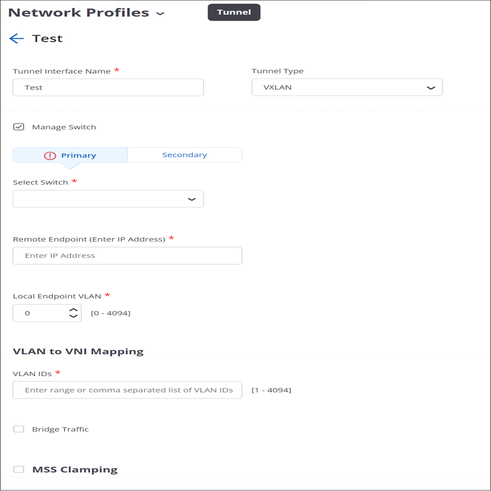
- For the Primary switch, select the switch name from the drop-down list. Only the available switches are listed in the menu. You will see only those switches that you have imported earlier and if they are not already applied to a different VXLAN profile.
- Specify the Remote Endpoint IP address. This is the loopback address that gets created on the switch.
- (Optional) Configure the Secondary switch.
- Specify the Local Endpoint VLAN where the AP creates the tunnel with the remote endpoint. Ensure that the remote endpoint is reachable from the local endpoint VLAN.
- Specify the VLAN IDs which are mapped to the VNI of the switch. As a best practice, create the VNIs on the switch and then map them here with respective VLAN.
- Enable Bridge Traffic.
- Enable MSS Clamping.
- Select Auto or Manual under Tunnel MTU Discovery. For the Manual case, set the appropriate tunnel MTU value.
- Save the settings.