Radio Settings
- About Radio Settings
- How Unified Client Steering Works
- Configure Client Steering Common Parameters in Radio Settings
- Configure Basic Radio Settings
- Configure 802.11ax Settings
- Configure 802.11be Enhancements
- Configure Transmit Power Selection in Radio Settings
- Configure Smart Steering in Radio Settings
- Configure Smart Client Load Balancing in Radio Settings
- Configure Band Steering in Radio Settings
- Configure WMM Admission Control Policy in Radio Settings
- Configure Ignore Low RSSI
- Frame Aggregation
About Radio Settings
The WiFi Radios tab in allows you to configure settings related to the Wi-Fi access point radios at a location.
The newer Wi-Fi 6E and higher model APs have four radios, where three radios are dedicated access radios and the fourth radio is a multifunction radio. The previous generation AP models had two and three radios respectively. For more information on AP models and radios, see the AP matrix under AP Platforms in https://www.arista.com/en/products/cloudvision-cue.
Each radio is assigned a dedicated band. You can configure radio settings for each of these bands using the 2.4GHz, 5GHz, and 6GHz tabs. There is also a Dual 5GHz band, where the 6GHz radio can be operated in a 5GHz band. In the 6GHz tab, the channels are arranged based on the UNII bands (UNII-5, UNII-6, etc.) because the number of allowed 6GHz UNII bands varies depending on the regulatory domain. Rest of the options are the same as the 5GHz or 2.4GHz bands. Dual 5GHz is hidden by default, but you can access it from the three-dots menu. 6GHz configurations are applicable only for Wi-Fi 6E and higher APs (such as C-360, C-460, O-435/E, etc.). Dual 5GHz configuration applies only to AP C-360.
By default, an Arista AP selects its operating channel automatically when in AP mode. It picks a channel with minimum Wi-Fi interference. The AP first selects a channel when it boots. Then, it periodically looks for a better channel and changes its operating channel if necessary; you can specify this period in the Selection Interval field. So, once every Selection Interval, the AP checks if the Wi-Fi interference on the current channel has increased. If the interference has increased, then the AP looks for a channel with minimum Wi-Fi interference and starts operating on that channel.
An Arista AP can steer a client to a different band or to another Arista AP. The Client Steering Common Parameters link at the bottom of the screen allows you to configure parameters common to both radios and to the different types of client steering. With these common settings, the different types of client steering work together towards the common goal of improving client Quality of Experience (QoE). For example, Smart Steering and Band Steering use the Common RSSI threshold as their reference. See What is Unified Client Steering for details.
Dual 5 GHz
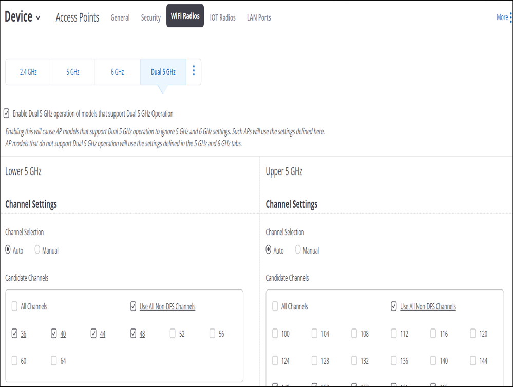
When Dual 5GHz is enabled, those configurations are given preference over 6GHz configurations. That is, if you configure all the three radios — 2.4, 5, and 6GHz, and then configure Dual 5GHz as well, then the AP ignores the configurations defined in 5GHz and 6GHz tabs.
Advanced Radio Settings
Under Advanced Radio Settings, you can configure transmit power, client steering and load balancing parameters, and admission control policies.
Transmit Power Selection
The Transmit Power value corresponds to the Effective Isotropic Radiated Power (EIRP). This is the value radiated by the antenna, i.e., the actual power transmitted "over-the-air". In case of external antennas, the transmit power at the AP port is adjusted according to the antenna gain to ensure that the power radiated over-the-air does not exceed regulatory restrictions.
- The maximum value allowed in the regulatory domain
- The maximum power supported by the radio
- The antenna gain
Smart Steering
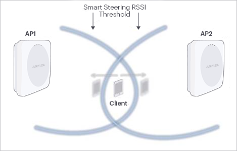
Smart Steering solves the sticky client problem. A sticky client is one that stays connected to an AP with poor signal strength, even when there is another AP that can offer better signal strength. In such situations, an Arista AP smartly steers a client to the better AP. Smart Steering thresholds ensure that an Arista AP does not steer clients too frequently, since that can worsen the QoE.
Smart Client Load Balancing
In high-density environments (auditoriums, lecture halls, conference centers, company meetings, etc.) where APs are densely deployed to provide bandwidth to all clients, a client sees multiple APs with very good signal strength. Most clients will connect to the AP/band with the best signal strength resulting in some heavily loaded APs. This could result in poor performance. Smart Client Load Balancing corrects this situation by steering clients to less loaded APs with good signal strength.
Band Steering
WMM Admission Control Policy
Wi-Fi Multi Media (WMM) prioritizes the network traffic based on four categories: voice, video, best effort, and background. You can make WMM Admission Control mandatory. If you do so, you must configure the admission control parameters for voice and video calls — the Maximum Allowed Calls count and the Maximum Share of Medium Time. You also need to set aside a fraction of these resources for roaming clients, under Roaming Reservation. This ensures that clients that roam on this SSID are guaranteed some resources when they are on a voice or a video call.
How Unified Client Steering Works
| Stage | Method | Short Description |
|---|---|---|
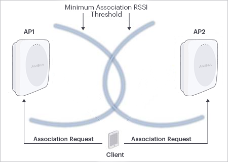
| Pre-Association | Min Association RSSI | Rejects association request if client’s RSSI is less than the configured threshold |
| Band Steering | Rejects association requests on 2.4 GHz for dual band clients. Band steering is unidirectional. The AP always steers a client from 2.4GHz to 5GHz because the 5GHz band has more non-overlapping channels and offers higher speeds. | |
| Smart Client Load Balancing | Rejects association request if the client load on an AP is high and less loaded neighbor APs are available | |
| Post-Association | Smart Steering | Disconnects client if RSSI drops below a certain threshold |
| Band Steering | When a 5GHz AP radio comes up after being down for a while (for example, due to Radar detection, auto channel selection epoch, or channel change due to high RF interference detection), AP steers dual band clients that were connected to 2.4 GHz when 5 GHz was down |
General Considerations
- APs must have a unified view of the network
- Clients should not be steered too frequently
Inter Access Points Sync
An AP must have a unified, client-aware view of the network. That is, it must know how the network looks to its neighboring APs and to clients – both its own clients and those of the neighbors. The AP can then make informed steering decisions to ensure optimum client QoE.
Example: Minimum Association RSSI
Frequency of Client Steering
APs must not steer clients too frequently. Clients that are moving or happen to be in the coverage overlap region of two APs could “ping-pong” between the two APs because of constant back and forth steering. This is wasteful signaling and could cause poor user experience.
To avoid this, Arista APs should not attempt to steer a client too often. You can configure a Steering Attempts Threshold parameter that determines the maximum number of attempts to steer a client allowed in a 10-minute window (see Configuration section for details). The default value is 2. So, if an Arista AP has attempted to steer a client twice in 10 minutes, the client enters a configurable Blackout Interval (default 15 minutes). The AP does not attempt to steer such a client until the Blackout Interval has elapsed. An Arista AP shares the steering attempt epochs of its clients with its RF neighbors in its periodic wired-side broadcasts.
Example: Smart Steering
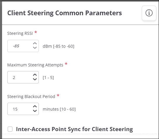
Configure Client Steering Common Parameters in Radio Settings
In Client Steering Common Parameters, the different types of client steering work together towards the common goal of improving client Quality of Experience (QoE).
- Navigate to
- Click the Client Steering Common Parameters link at the bottom of the screen.
- Enter value for Steering RSSI Threshold.
- Set max number of steering attempts for a client in Steering Attempts Threshold field.
- Set steering suspension period for a client in Steering Blackout Period field.
- Click Save.
What is Unified Client Steering
An Arista AP can steer a client to a different band or to another Arista AP. Clients can be steered before or after association. The decision to steer a client is based on considerations such as signal strength, load (i.e. number of clients connected to the radio) and the preferred band of operation. While client steering is important for best user Quality of Experience (QoE), frequent and ad-hoc steering of the client can in fact worsen the QoE. Arista APs use an approach called Unified Client Steering. In this approach, APs exchange information with each other, resulting in a “big picture” view of the client experience. Different types of client steering then work together towards the common goal of improving client QoE. For example, Smart Steering and Band Steering use the Common RSSI threshold as their reference.
Client Steering Parameters
| Field | Description |
|---|---|
| Client Steering Common Parameters | |
| Client Steering Common Parameters | Client Steering Common Parameters can be configured only on11ac devices. |
| Steering RSSI Threshold | The steering RSSI threshold can be between -60 to - 85 dBm. Default value is -70 dBm. |
| Steering Attempts Threshold | This is the max number of steering attempts for a client within a 10 minutes window after which the client's steering is suspended for a period specified by Steering Blackout Period. The default value for steering attempts is 2. The minimum value is 1 and maximum value is 5. |
| Steering Blackout Period | This is the steering suspension period for a client. No steering methods would be employed for a client if it sojourns within this time period. The default value for steering blackout period is 15 minutes. The minimum value is 10 minutes and maximum is 60 minutes. |
Configure Basic Radio Settings
You can configure Radio Settings for both 2.4GHz and 5GHz. The configuration is location specific.
- Navigate to
- Select the RF Regulatory Domain.
- Select the frequency band under Wi-Fi Radios tab.
- Configure the Operating Channel section.
- Choose Auto or Manual Channel Selection. Choose from:
- If Channel Selection is Auto, then provide appropriate values for the fields below.
- Channel Width
- Selection Interval in hours
- Selection Mode - Select Scheduled to run ACS at a specific time of the day and minimize service disruption. Select Periodic to run ACS at defined time intervals.
- Dynamic Channel Selection to enable automatic switching of the current channel to an available channel with lower interference.
- Select Candidate Channels depending on the chosen Wi-Fi Regulatory Domain.
- If Channel Selection is Manual then provide the appropriate Channel Number.
- If Channel Selection is Auto, then provide appropriate values for the fields below.
- Click Save.
Basic Radio Settings Parameters
| Field | Description |
|---|---|
| Operating Region | Contains list of region or country, default it United States. User is allowed to change it if he has an entitlement or license. |
| Frequency Band | The radio frequency band. You can configure the radio frequency for 2.4 GHz, 5 GHz, 6 GHz, and Dual 5 GHz. Default value is 2.4 GHz. |
| Channel | |
| Operating Channel | The operating channel for the radio. By default, the AP automatically selects the operating channel as automatically (Auto). User can manually set the channel if desired. Select Manual, to set the operating channel. Based on the location selected, a list of channel numbers are presented for manual channel selection. If the manually selected channel is not present in the country of operation selected for the device in the applied AP template, the AP automatically reverts to Auto mode and selects a channel. |
| Channel Width | The channel width for the radio. Possible values are 20 MHz or 20 MHz /40 MHz. In case of a/n/ac devices, the 20/40/80+80 MHz and 20/40/80/160 MHz options are available. The options are enabled for 2.4 GHz, 5 GHz, and 6 GHz modes. |
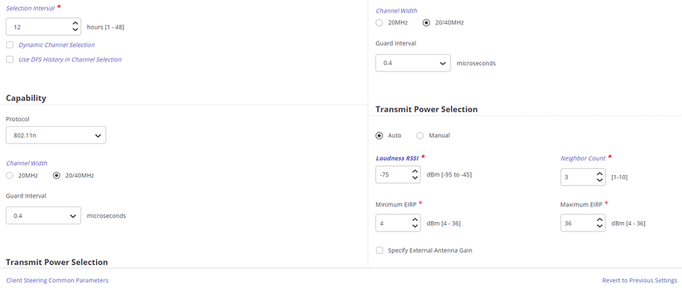
| Selection Interval | This field is visible only when the Operating Channel is set to Auto. This field specifies the time interval, in hours, at which the channel selection happens. You can enter any value from 1 to 48. The channel may change automatically after this time interval if some other channel is found to have lower interference than the current channel. |
| Dynamic Channel Selection | This field is visible only when the Operating Channel is set to Auto . Select the Dynamic Channel Selection check box to enable automatic switching of the current channel to an available channel with lower interference, when the interference on the current channel increases. The mechanism is independent of the Selection Interval, and channel is changed only when the interference on current channel is very high. |
| Candidate Channels | This field is relevant in case of auto-channel selection. It enhances the behavior of auto-channel selection. The AP dynamically checks if the current channel interference has increased and selects a channel with lower interference and diverts the traffic to this channel. For countries where channel 13 or above are permitted on the b/g band, only the channels 1,5,9,13 are selected, by default. You can modify the candidate channel list. |
| Auto Channel Selection(ACS) Mode | ACS has two selection modes, Scheduled and Periodic. In Scheduled ACS, you can define the duration in hours and minutes. The AP radio checks for interference and contention every day during the scheduled time. You can also specify a secondary time to run the ACS. The duration between the two scheduled ACS must be at least 60 minutes. Else, you will receive an error message and you will not be able to schedule the ACS. The Scheduled ACS is a per-radio setting. So, you need to define the ACS schedule for each band. In Periodic ACS, you can specify the time duration in hours, to run ACS at pre-defined time intervals. |
Configure 802.11ax Settings
MU-MIMO
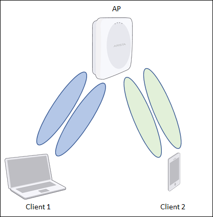
Multiple Input Multiple Output (MIMO) refers to the use of multiple antennas on Wi-Fi APs and clients to increase data rates (via spatial multiplexing) and reduce interference (via spatial diversity). Multiple antennas result in multiple, simultaneous “streams” of data between an AP and a client on the same channel. Multi-user MIMO (MU-MIMO) uses the multiple-antenna streams not to improve the transmission to a single user but to simultaneously serve multiple users, i.e., to improve capacity rather than user data rates. The figure below shows an example of MU-MIMO where four streams on the AP can simultaneously serve two clients, each with support for two streams.
Downlink MU-MIMO
Depending on the channel conditions of a client, an AP can use Single User MIMO (SU-MIMO) to improve the client’s data rates or reduce its error rates. Both, however, are per-link improvements. Since dense environments are about capacity and not just individual user data rates, downlink MU-MIMO can help in dense environments by allocating resources (i.e. streams) more efficiently among a large number of users. 802.11ax supports 8x8 MIMO on the downlink, i.e., an AP can simultaneously send data to eight users.
Uplink MU-MIMO
Uplink MU-MIMO is especially useful for uplink-heavy applications such as social media, content sharing, and video calls. As with the downlink, uplink MU-MIMO increases capacity compared to the SU-MIMO case. This results in a better user experience when uploading content. 802.11ax supports 8x8 MIMO on the uplink, i.e., eight users can simultaneously send their data to an AP. Early 802.11ax Wi-Fi clients might not support uplink MU-MIMO and for the ones that do, the implementation is not yet mature across client manufacturers. If your 802.11ax network has throughput problems, you might want to disable uplink MU-MIMO.
OFDMA
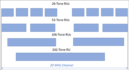
Orthogonal Frequency Division Multiple Access (OFDMA) divides the Wi-Fi channel into subcarriers, also called “tones”, each 78.125 KHz wide. Tones are combined to form Resource Units (RUs) of different widths. As shown in the representation below, an RU can consist of 26, 52, 106, or 242 tones—corresponding to channel widths of approximately 2 MHz, 4 MHz, 8 MHz, and 20 MHz. In each scheduling interval, OFDMA allocates one or more RUs of different widths to multiple users, resulting in an efficient and flexible use of the channel.
802.11ax uses OFDMA to support multiple users simultaneously, but the underlying multiple access mechanism continues to be CSMA-CA with backoff. Users are scheduled simultaneously, but only when CSMA-CA determines that the medium is available for transmission.
Downlink OFDMA
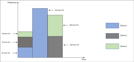
In the first scheduling interval, the AP allocates two 52-tone RUs to Client 1 and Client 2, and one 26-tone RU to Client 3. In the second interval, it allocates the whole 20 MHz channel—a single, 242-tone RU—to Client 1. And in the third interval, it allocates two 106-tone RUs to Client 2 and Client 3.
Uplink OFDMA
The Wi-Fi uplink is a distributed form of communication because the transmitters (i.e., clients) cannot coordinate their schedules (unlike the downlink, where the AP is both the transmitter and the scheduler). Until 802.11ac, Wi-Fi uplink was uncoordinated: clients contended for the medium and, based on randomly distributed timing, sent packets to the AP. This works reasonably well for single or sparse AP deployments, but for dense deployments, this can cause high uplink contention in presence of a large number of clients. With 802.11ax, the Wi-Fi uplink is coordinated. The AP manages the uplink resource allocation via mechanisms that essentially coordinate the transmission schedule among clients while using CSMA-CA to ensure that the medium is available for transmission. This leads to reduced uplink contention, thereby improving capacity and user experience. Early 802.11ax Wi-Fi clients might not support uplink OFDMA and for the ones that do, the implementation is not yet mature across client manufacturers. This may adversely affect the 802.11ax AP throughput. If your 802.11ax network has throughput problems, you might want to disable uplink OFDMA.
Spatial Reuse
With spatial reuse, two or more Wi-Fi devices (AP or client) that support 802.11ax protocols can send transmissions simultaneously without any significant data loss. Spatial Reuse helps in improving the spectral efficiency and optimal allocation of resources to meet the Quality of Service (QoS).
How Spatial Reuse Improves Efficiency?
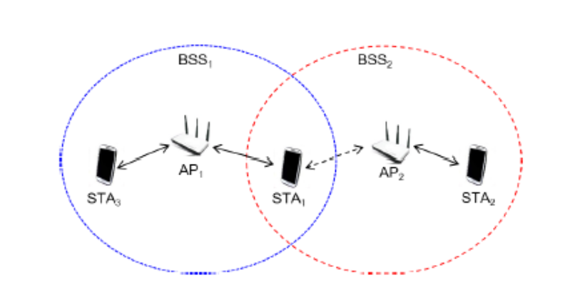
BSS1 and BSS2 operate on the same channel and can hear each other with an RSSI higher than the Clear Channel Access Signal Detection (CCA-SD) level, the threshold that Wi-Fi devices use to decide if the channel is clear to transmit or if they need to wait for the . A co-channel BSS that can be heard at an RSSI greater than the threshold is called an overlapping BSS (OBSS). Thus, BSS2 is an OBSS for BSS1, and vice versa.
Before Wi-Fi 6, if a Wi-Fi device detected an ongoing transmission with RSSI higher than CCA-SD on a specific channel, all other devices on the same channel had to back off and they would wait for the ongoing transmission to get over. With Wi-Fi 6, a device can leverage spatial reuse to transmit in parallel with an ongoing OBSS transmission, provided the spatial reuse transmission is at an acceptably low transmit power.
BSS Color
A Wi-Fi device that wants to transmit using spatial reuse needs to distinguish the transmissions of its own BSS from those of the OBSS. To enable this, Wi-Fi 6 introduces BSS color, an integer between 1 and 63 to identify a BSS. An AP radio automatically assigns a BSS color to each transmission. When two radios transmit on the same channel, BSS color helps an AP to differentiate between an inter-BSS transmission and intra-BSS transmission.
Typically, every 802.11ax HE (High Efficiency) frame contains a BSS color value that a Wi-Fi device can use to identify the frame as its own BSS or an OBSS. The BSS color is signaled in the 802.11ax PHY preamble, allowing for early detection of an OBSS transmission. Since a Wi-Fi 6 device instantly decodes the HE preamble, the device can identify an OBSS transmission well in advance to transmit in parallel.
As long as BSSs in vicinity of each other use distinct BSS colors, a device can distinguish the transmissions of its own BSS from those of an OBSS.
Enabling Spatial Reuse
- Click the WiFi Radio tab.
- Select a frequency band and scroll down to 802.11ax Enhancements.
- Click the Spatial Reuse (SR) checkbox.
- Specify your OBSS Packet Detection Threshold. If the RSSI of an ongoing BSS transmission is below the specified level but within the range of -81 to -62 dBm, the OBSS device can transmit in parallel.
- Save the settings.
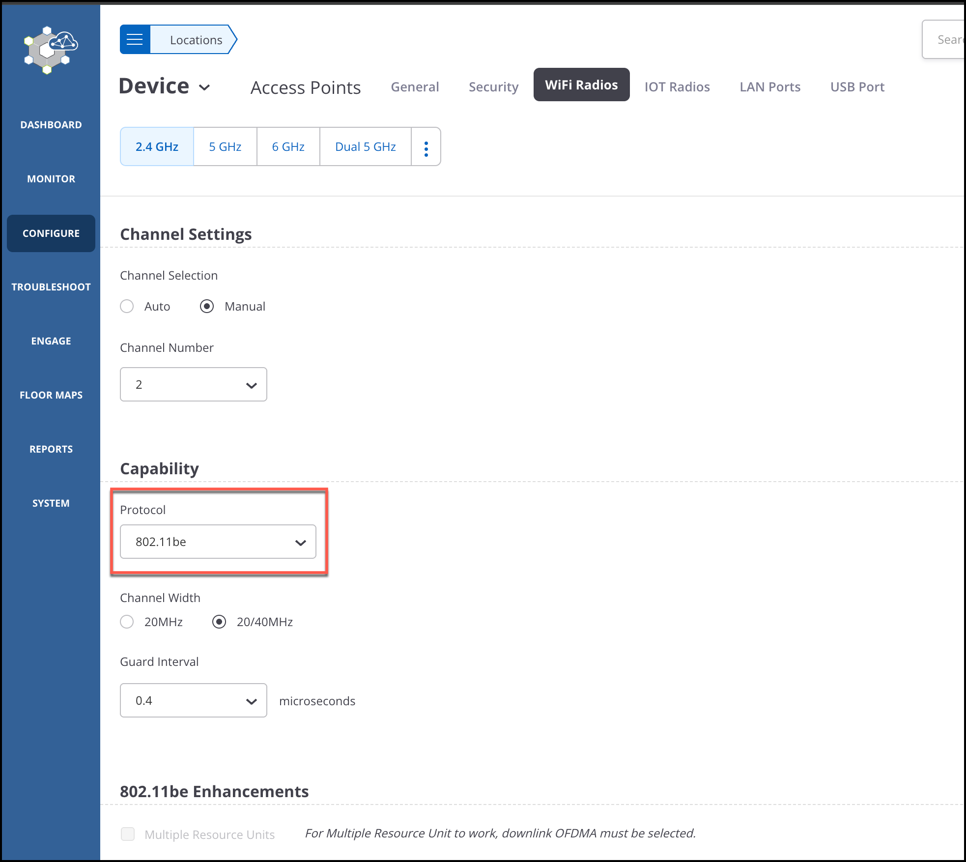
Configure 802.11be Enhancements
The 802.11be standards build on 802.11ax by providing ultra-high throughput, improved resource utilization, and interference mitigation. The 320 MHz support increases the throughput and performance in the 6GHz band. The improved resource utilization is attributed to the introduction of Multiple Resource Units (MRU) in Orthogonal Frequency Division Multiple Access (OFDMA) transmission and Multi-Link Operation (MLO).
- Multiple Resource Units (MRU)
- Preamble Puncturing
- Multi-Link Operation
- Support for 320 MHz Channel Bandwidth
Multiple Resource Units
Multiple Resource Units (MRU) is an enhancement to RU introduced in 802.11ax. With MRU, the AP can allocate multiple, non-contiguous resource units (RU) to a single client device. This feature significantly improves resource utilization when used with the puncturing of RU.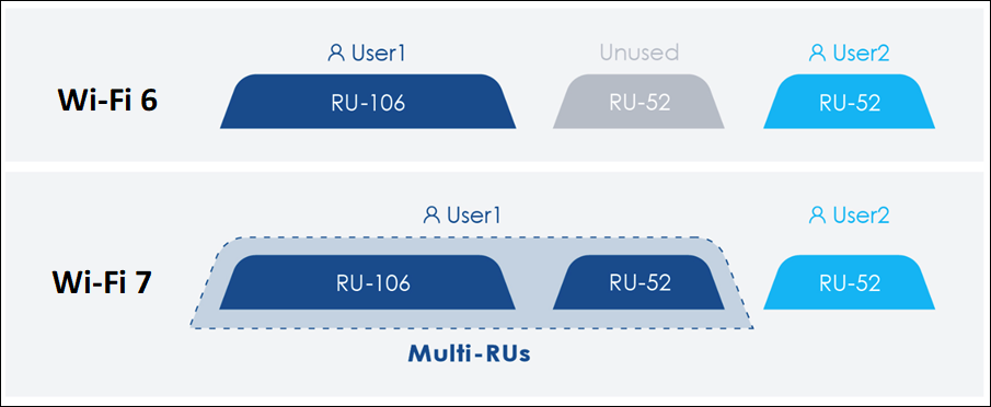
Enabling Multiple Resource Units
- Click the WiFi Radio tab.
- Select a frequency band and scroll down to 802.11be Enhancements.
Note: As a prerequisite, select Downlink OFDMA and Uplink OFDMA.
- Click the Multiple Resource Units checkbox.
- Save the settings.
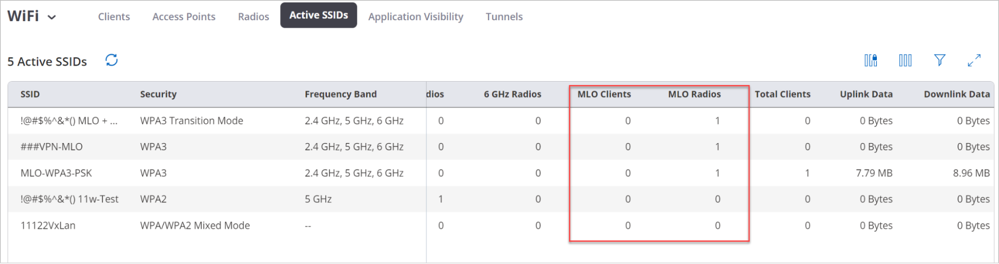
Verification
To verify MRU, check the AP logs. You can also see the status on the SSID card view.
Preamble Puncturing
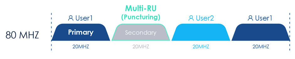
Preamble Puncturing is the ability to not send the preamble for a given 20 or 40 MHz channel, indicating that the ensuing data will not be present in that 20 or 40 MHz channel. Except for the primary 20 MHz or 40 MHz channels, the AP can puncture the secondary or other channels. Preamble Puncturing is not supported in the 2.4 GHz band because the AP cannot puncture 20 MHz and 40 MHz channels.
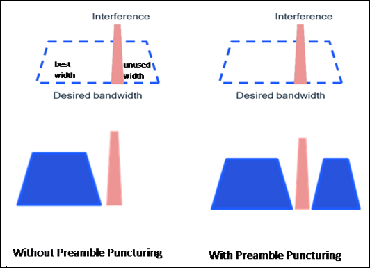
When you enable Preamble Puncturing, the AP uses proprietary algorithms to identify interference in the 5 GHz or 6 GHz band and punctures the interfering RU. It transmits data with the punctured RU for 30 minutes. After 30 minutes of transmission, the AP scans for interference again, and if it doesn’t find any, it stops the puncturing.
Preamble Puncturing improves clients' overall bandwidth utilization by utilizing all available RUs for data transmission. With Preamble Puncturing, APs can puncture the worst-performing RUs, and therefore, administrators can allocate 80 or higher MHz RUs depending on demand. You do not have to restrict yourself to allocating just 20 or 40 MHz RUs.
The AP uses the puncturing resolution of 20 MHz in 80 MHz and 160 MHz. The puncturing resolution in a 320 MHz channel is 40 MHz.
Enabling Preamble Puncturing
- Click the WiFi Radio tab.
- Select a frequency band and scroll down to 802.11be Enhancements.
- Click the Preamble Puncturing checkbox.
- Save the settings.
Verification
To verify the punctured width from the RF Explorer:
- Go to MONITOR > WiFI > Radios.
- Scroll down to the Channel Map widget and select RF Explorer.
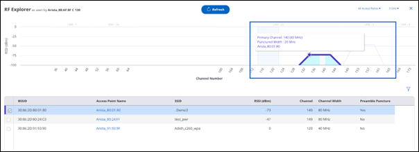
You can also verify if a radio has Premable Puncturing enabled from the Radio listing or from the Radio Properties right panel.
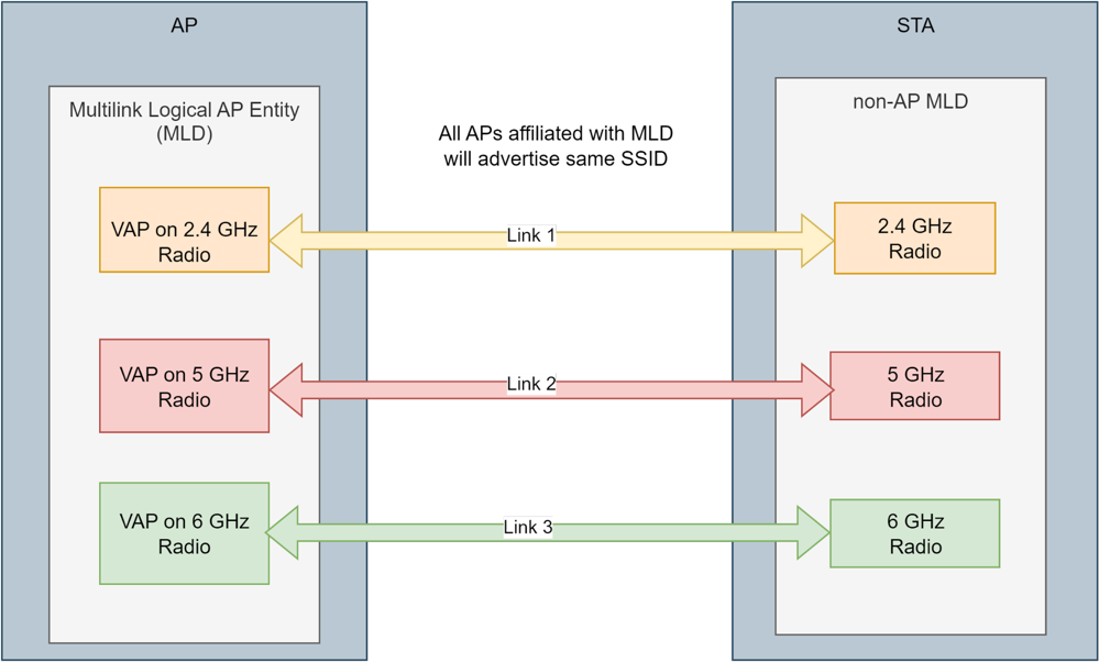
Multi-Link Operation with 802.11be Protocol
Until now, a multi-band client (for example, a phone with 2.4, 5, and 6 GHz radios) could connect to an Access Point (AP) using only one of the bands. Therefore, only one connection link is formed between the client and the AP. Multi-link Operation (MLO) is the capability of the client and the AP to connect to more than one band simultaneously, thereby establishing multiple links. Clients that can connect to the Access Point over multiple radio links simultaneously are called Multi-Link Devices (MLD).
Establishing multiple communication links reduces access latency and enables bandwidth aggregation, resulting in increased throughput. With MLO, Wi-Fi 7 Access Points broadcast the same SSID on all radios (2.4, 5, and 6 GHz), using the 802.11be protocol, allowing MLO-capable clients to connect to all bands or a combination of bands simultaneously.
Supported Platforms (Wi-Fi 7 Access Points):
-
C-460(E)
-
O-435(E)
-
C-430
-
C-400
Auto-Enabled MLO with 802.11be Protocol

Verification
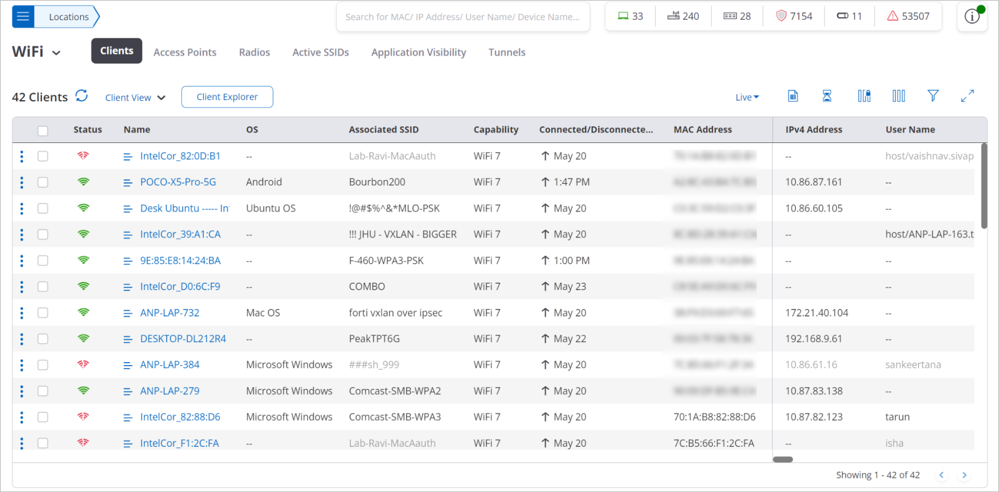
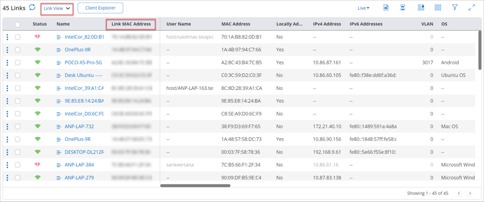
MLO Client Details
The client view tab is divided into 2 grids, client view and link view.
Client View
Link View
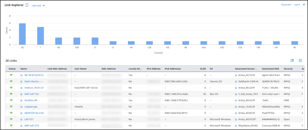
You can view the same information in a graphical format through the Link Explorer.
Wi-Fi Analytics for MLO Clients
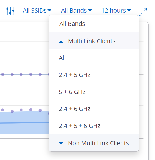
- Overview Dashboard
- Connectivity Chart:
- Baseline - Clients Affected by Failure
- Performance Charts:
- Baseline - Clients Affected by Poor Performance
- Clients by Avg. Data Rate
- Clients by RSSI
- Clients by Retry Rate %
- Network Usage
- Application Charts:
- Application Experience
- Baseline - % Poor Application Experience
Upgrading to the 21.0 Release
Pre-Upgrade Steps
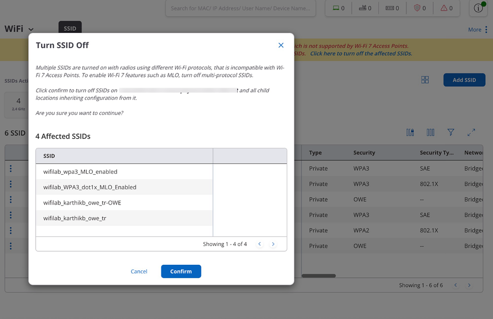
Before upgrading to the 21.0 release, Arista recommends network administrators verify all SSIDs for mixed radio protocols. Since mixed-protocol SSIDs are not allowed, network administrators must correct them by disabling the mixed-protocol SSIDs and resolving the protocol conflict to ensure network connectivity. Either configure all radios in the SSID to use 802.11be or downgrade all radios to a non-802.11be protocol. Until this is completed, client connectivity may be disrupted.
Post-Upgrade Steps

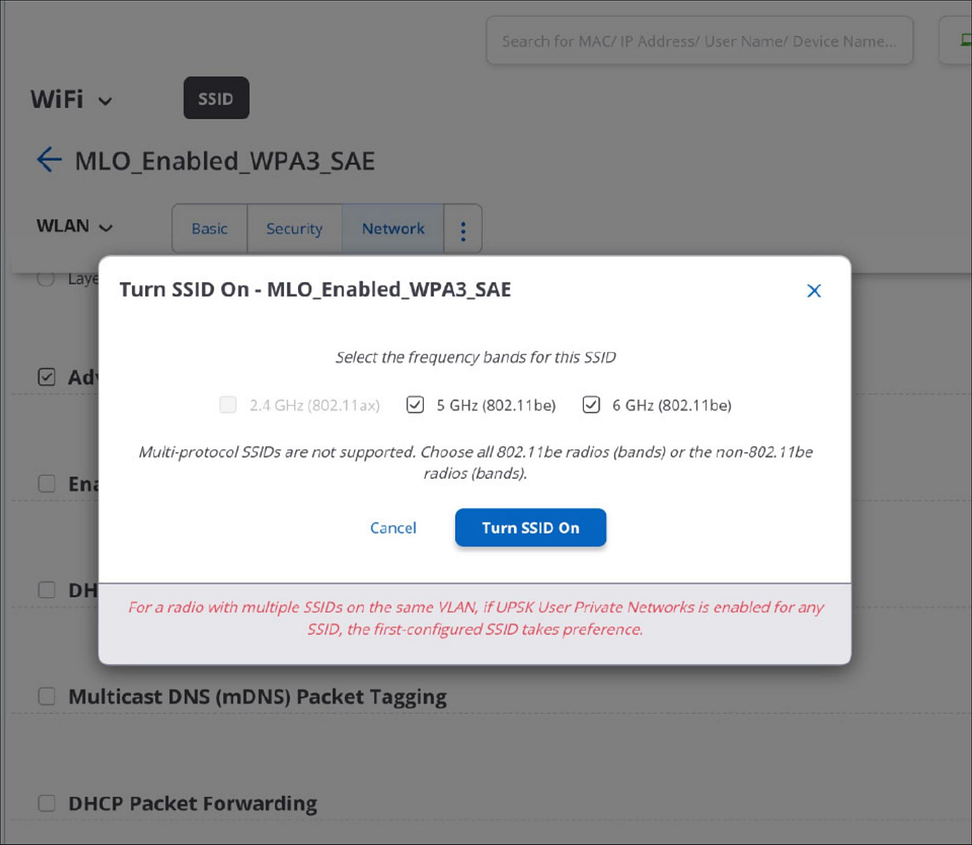
Note: From the 21.0 release, the Wi-Fi 7 tab in the SSID configuration is removed, as MLO is automatically enabled when the 802.11be protocol is selected.
Configure Transmit Power Selection in Radio Settings
You can fix the transmit power of an AP manually or you can configure an AP to automatically adjust its own transmit power.
- Navigate to
- Click WiFi Radios tab,
- Move to Transmit Power Selection Settings.
- Select Auto option.
- Enter the appropriate values for the following fields.
- Loudness RSSI
- Neighbor Count
- Minimum Transmit Power
- Maximum Transmit Power
- Select Manual option.
- For access points that use an external antenna, select Use External Antennas and enter the External Antenna Gain in dB.
- Click Save.
Transmit Power Selection Parameters
| Field | Description |
|---|---|
| Advanced Radio Settings | |
| Transmit Power Selection (Auto and Manual radio buttons) | This field enables you to control the transmission power of the AP. It is a mandatory field.
|
| Loudness RSSI | An AP is considered loud if it can be heard by a neighbor AP with an RSSI greater than this value . Allowed range is -95 dBm to 0 dBm. The default is -75 dBm. |
| Neighbor Count | Maximum number of allowed loud neighbor APs. Allowed range is 1 - 10. The Default value is default 3. |
| Minimum Transmit Power | Minimum transmission power. Allowed range is 4 - 30 dBm. The Default value is 4 dBm. |
| Maximum Transmit Power | Maximum transmission power. Allowable range is 4 - 30 dBm. The Default value is 30 dBm. |
Configure Smart Steering in Radio Settings
Smart Steering feature helps you to resolve the issue of sticky client.
- Navigate to
- In the Smart Steering section enter the time interval, in seconds for Roam Initiation Interval.
Info:Roam Initiation Interval is the time interval, for which the client's signal strength should be lower than the Roam Initiation RSSI Threshold for the AP to initiate the roam. The time can range from 5 to 900. Default value is 10.
- Enter the RSSI threshold to disconnect a client in Roam Initiation Packet Threshold field.
Info:When the signal strength of the client is less than this threshold, the AP disconnects the client and initiates a roam. The packet threshold can be between 5 to 500. Default value is 5.
- Click Save.
Configure Smart Client Load Balancing in Radio Settings
Smart Client Load Balancing is configured per SSID but it acts per radio. The radio is shared by all SSIDs associated with the band (2.4 or 5GHz). Balancing clients across APs provides each client a larger slice of radio time. The balancing mechanism may deny immediate access to the AP when a client roams. Clients that use real-time applications such as video and voice may be impacted. It is not recommended that Smart Client Load Balancing be enable on SSIDs that support real-time applications.
- Navigate to
- In the Smart Client Load Balancing section enter the minimum number of clients that can connect to an AP in Minimum Client Load field.
Info:This field lets you specify the minimum number of clients that can connect to an AP before client load balancing is triggered. The default value for this field is 30 and the threshold is 45. The minimum client load on each radio is taken into consideration while the load on a single AP is checked.
- Enter The minimum difference between the number of clients connected on neighboring APs in Minimum Client Load Difference field.
Info:This minimum difference is considered to balance client load. Default value is 5 and range varies from 2 to 10.
- Click Save.
Configure Band Steering in Radio Settings
Band steering is a load balancing feature that lets the Wi-Fi client switch to the other available band to balance the load of the Arista access point in case more clients are operating on a single band.
To configure Band Steering in Radio Settings:
- Navigate to
- Scroll down to Band Steering section.
- Enter the value for Band Steering Client Load Difference.
Info:It is the load balancing parameter that is useful for tuning the load distribution between 2.4 GHz and 5 GHz bands. If the difference between the number of clients associated in 5 GHz and 2.4 GHz exceeds the threshold, band steering to 5 GHz is not performed until the difference comes below the threshold. Default value for this field is 25 and the threshold is 50.
- Click Save.
Configure WMM Admission Control Policy in Radio Settings
Wi-Fi Multi Media (WMM) prioritizes the network traffic. Configuration is done for the admission control parameters for voice and video calls. All the fields involved in configuration will be configured depending upon the choice made between video or voice calls.
- Navigate to
- Scroll Down to WMM Admission Control Policy.
- Select Admission control policy as Voice Calls or Video Calls.
- Select Admission Control Mandatory to make admission control mandatory.
- Select No Ack Policy to enable no acknowledgement policy.
Info:When you enable no acknowledgement policy, the acknowledgement for the unicast QoS data packets is not required from the receiver. No retransmission take place for the QoS data packets when the no ack policy is enabled.
- Provide the maximum number of allowed voice or video calls depending upon choice in Maximum Allowed Calls field.
Info:Limit for number of voice calls is 127.
- Enter the maximum percentage share of the medium time for voice calls in Maximum Share Of Medium Time field.
Info:The value for maximum percentage share ranges from 0 to 100. Default value is 0.
- Enter the number of voice calls reserved for roaming clients in Call Reserved field.
Info:The range for this field is from 0 to the number of maximum allowed calls specified in Maximum Allowed Calls field.
- Enter the percentage share of the medium time reserved for roaming clients in Share Of Medium Time Reserved field.
Info:The range for percentage share is from 0 to the percentage share specified in Maximum Share Of Medium Time field.
- Click Save.
Configure Ignore Low RSSI Packets in Radio Settings
In high-density deployments, interference and noise are often high. By restricting APs to listen only to clients whose RSSI is above a threshold, the AP can ignore packets from low-RSSI clients. By raising the CCA-ED threshold, the AP can still transmit beacons despite a high noise floor.
Introduction
In high-density deployments, interference and noise are often high. Due to the high client density, most Access Points (AP) can hear all clients, especially probe requests. Also, if the Clear Channel Assessment - Energy Detection (CCA-ED) threshold is low, APs find it difficult to transmit beacons because the channel is not assessed to be clear due to the high noise level. The network is always busy, and the noise floor is always high, affecting the overall network performance and connectivity.
By restricting APs to listen only to clients whose RSSI is above a threshold, the AP can ignore packets from low-RSSI clients. For example, if you set the RSSI threshold to -65 dBm, the AP will ignore all Rx packets with an RSSI below this value.
By raising the CCA-ED threshold, the AP can still transmit beacons despite a high noise floor. For example, if you set the CCA-ED threshold to -55 dBm, the AP will continue to transmit beacons and other frames as long as the noise level remains below this value.
Configuring Ignore Low RSSI Packets
The Ignore Low RSSI Packet threshold is a radio setting, and you can configure it for each band. You must define the threshold for Rx power (signal strength) and Tx power.
Follow these steps:
- Go to .
- Select the WiFi Radios tab.
- Navigate to the Ignore Low RSSI Packets section and select it.
- Provide a value for RSSI Threshold. The acceptable range is -85 to -60 dBm.
- Provide a value for CCA-ED Threshold. The acceptable range is -85 to -45 dBm.
- Save the settings.
Behavior of Common Steering RSSI
The Client Steering Common Parameters include Steering RSSI, a common setting to determine the client's signal strength. Ignore Low RSSI Packets also includes an RSSI Threshold that determines the client's signal strength. To avoid conflicting settings, when you configure Ignore Low RSSI Packets, the Steering RSSI is disabled, and you can't make any changes.
Note that Steering RSSI is a common setting that applies to all bands, but Ignore Low Packet RSSI is a per-band setting. So, if you configure Ignore Low RSSI Packets for one band but do not configure it for other bands, then Steering RSSI is disabled for that band but remains unchanged for other bands.
The multi-function radio (MFR) will have the lowest threshold among all the radios.
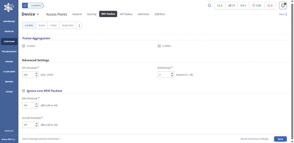
Frame Aggregation
Frame Aggregation is a MAC enhancement that reduces 802.11 protocol overhead and maximizes throughput by grouping multiple data frames in a single transmission.
- Logical Link Control (LLC)
- Media Access Control (MAC)
When the Network Layer sends a packet to the Data Link Layer, it is handed off to LLC and is called a MAC Service Data Unit (MSDU). When the MSDU is sent to the MAC sub-layer, a MAC header is added to the frame, and it becomes MAC Protocol Data Unit (MPDU). The MPDU is further encapsulated at the Physical layer.
- Aggregated MSDU (A-MSDU): Allows multiple MSDUs to be encapsulated within a single MPDU, which reduces MAC header overhead.
- Aggregated MPDU (A-MPDU): Allows multiple MPDUs to be encapsulated with a single PHY header.
A-MSDU and A-MPDU are enabled by default.
- Select .
- Select the WiFi Radios tab and navigate to the Frame Aggregation section.
- Select the A-MSDU and A-MPDU check boxes.
- Save the settings.