Device Settings
Under Device Settings, you can configure Device related settings such as Background
Scanning and Security related settings such as WIPS. Device Settings is available as a
submenu in CONFIGURE. 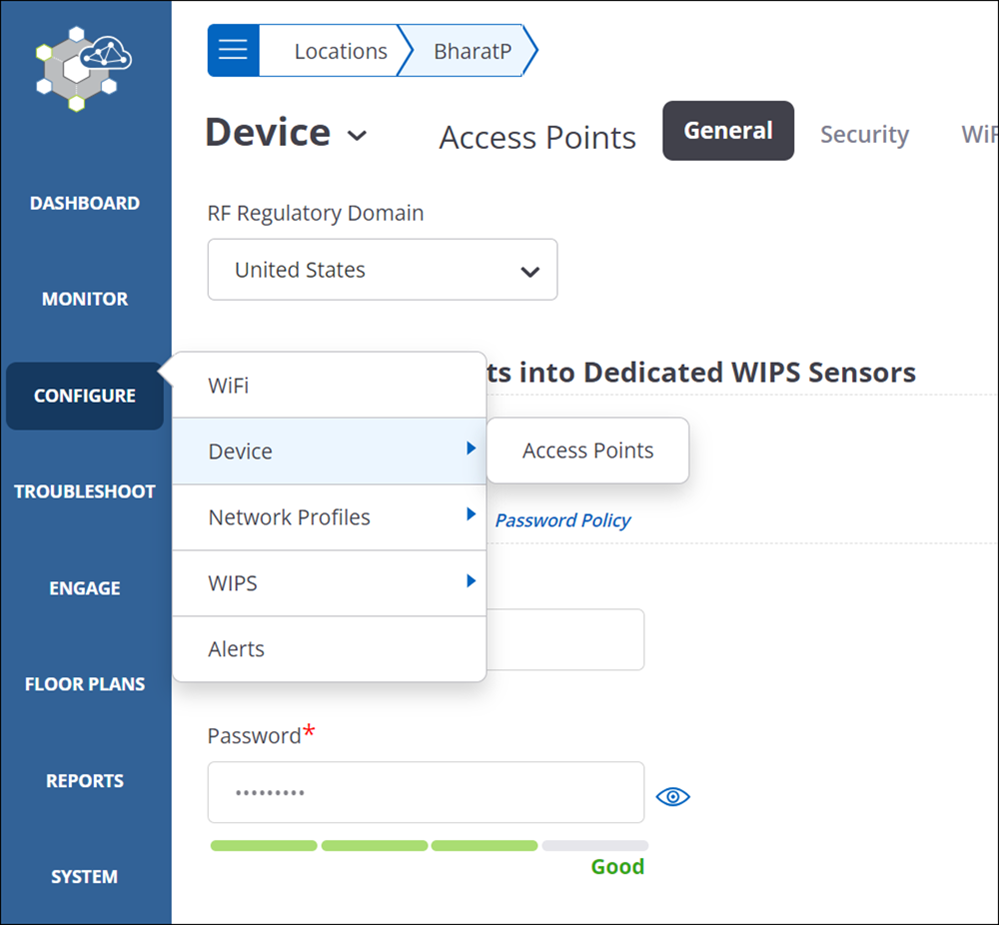
Configurations in Device Settings typically apply to a device, i.e., to all the radios of the device. Since an Arista AP can operate as an access point and/or as a WIPS sensor, Device Settings in CV-CUE is further divided into two tabs: Device tab and Security tab.
You can make changes to Device Settings even when the AP is offline, i.e., not connected to the Wi-Fi Server. The server pushes the changes onto the AP when the AP reconnects with the server.
- Device Tab
- Turn Access Point into a WIPS Sensor
- Configure Scanning
- Configure Missing VLAN Detection
- Configure Inter Access Point Sync for Client Steering in Device Settings
- Configure Client RSSI Update Interval in Device Settings
- Configure VLAN Extension in Device Settings
- Configure Link Aggregation in Device Settings
- Configure LAN1 as Preferred Primary Uplink
- Configure AeroScout Integration
- Configure Antenna Settings in Device Settings
- Configure Device Password in Device Settings
- Send Client and Access Point Logs to Syslog Server
- Configure IPv4/IPv6 Dual Stack in Device Settings
- Enable SSH IP Allow List
- Enable Multiple VLAN Registration Protocol
- Configure NTP in Device Setting
- Configure Maximum Transmission Unit
- Configure Access Radio Exceptions in Device Settings
- Device Security Settings
- Configure BLE Settings
- Configure Bluetooth Scanning
- Configure Uplink Port Authentication for Access Point
- Configure VLAN Monitoring in Device Settings
- Configure WIPS Settings in Device Settings
- Send Device Analytics to a Third-Party Server
- Configuring SESimagotag Retail IoT Connector with Arista APs
- Customize Device Attributes for Location Specific Overrides
Device Tab
You can configure AP-related settings such as Background Scanning on the Device Tab.
You can turn the access point into a WIPS sensor on the Device tab. When you do so, CV-CUE permanently erases Wi-Fi access related settings (Background Scanning, for example) in that folder.
You can enable Background Scanning on the Device tab. When you enable Background Scanning, an access point radio periodically scans channels in its band (2.4GHz or 5GHz). You can configure for how long the AP scans channels (say, for 100ms) and how often it does so (say, every 10 seconds). An Arista AP uses information obtained during a background scan mainly for two purposes: performance optimization (e.g. Dynamic Channel Selection, Client Steering) and security (e.g. WIPS rogue AP detection). As a result, many of the RF Optimization features require Background Scanning to be enabled.
With Inter-Access Point Sync for Client Steering, APs exchange client information with each other. This helps steer clients between APs. Bluetooth Low Energy (BLE) is used for proximity based services on mobile devices via an application ecosystem. Arista APs now support the iBeacon BLE standard. You can set the BLE iBeacon parameters in Device Settings.
VLAN Extension applies only to specific APs (AP Feature Matrix) and only when it is in AP mode (i.e. not configured as a sensor). VLAN Extension allows you to map a LAN port to a VLAN ID. It is essentially a way to extend your wired network - a typical use case could be plugging a laptop in to one of these ports to connect directly to the wired network.
AeroScout Tags are small, battery-powered devices mounted on equipment or carried by personnel. The AeroScout Engine Server (AES) determines the location of these tags based on the signal strength information that it receives from Arista Wi-Fi Access Points (APs).
Antenna Settings allow you to choose whether APs at the location use internal or external antennas.
Device Password allows you to set the username and password for APs at the location.
You can enable Device Access Log and specify the hostname or IP address of a Syslog server to which you want AP to send their access logs.
IPv4/IPv6 Dual Stack enables both stacks in the APs.
Enable SSH IP Allow List allows you to restrict the IP addresses that are allowed to SSH to Arista APs.
NTP Configuration defines three NTP servers that an Arista AP uses to get its clock reference.
When you enable Analytics Integration with Third Party Server, an Arista AP sends analytics information to an external server. You can specify the format in which the analytics information is sent, the server URL, and the interval for sending the analytics.
Access Radio Exceptions apply to single radio APs or to dual-radio APs that can operate in a "combo" mode with one radio in access mode and the other one in WIPS mode. For Single Radio APs, you can select the band you want the AP to operate on. For Dual Radio AP-Sensor Combo APs, you can select the band of operation of the access radio.
Turn Access Point into a WIPS Sensor
Turning access points into a WIPS sensors permanently erases Wi-Fi access related settings at the selected folder.
- Navigate to .
- Select Turn Access Point into Dedicated WIPS Sensor.
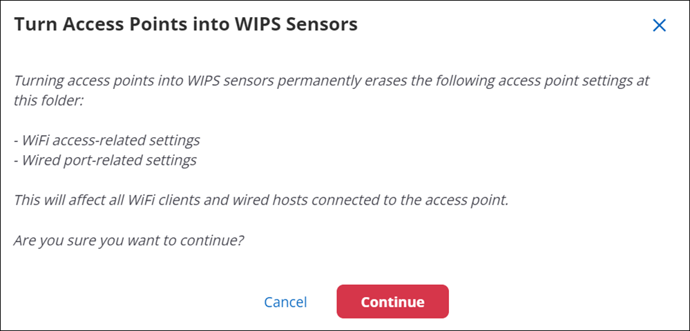
- Click Continue to turn APs into WIPS sensor.
- Click Save.
Configure Scanning
Arista APs have the capability to scan the radio channels at a periodic interval. The scan duration and the interval at which the scans must run can be configured.
The available scanning options are: Background Scanning VoIP Scanning No Scanning Do not enable background scanning if the radio is being used for Voice over IP (VoIP). If No scanning is selected, then features such as "Smart Client Load Balancing", "RF Neighbors", "Smart Steering, and "Minimum RSSI Based Association" configured in the SSID profile will be rendered non-functional. Background Scanning A method where a radio providing Wi-Fi access service scans off-service channels intermittently. The scan timings are variable and can be configured by the user. By default, the scan duration and access duration is 100ms and 10ms respectively. For multi-radio devices, background scanning is disabled by default as the one of the radios is always in WIPS mode. To know more about parameters required in configuring Background Scanning refer Background Scanning Parameters. VoIP Scanning Background scanning can disrupts high-bandwidth applications like voice and video. To avoid this disruptive behavior, use VoIP Scanning on radios containing SSIDs that are used for high bandwidth applications. If VoIP Scanning is enabled, the AP performs a quick scan of channels for a duration of 30 ms instead of a full scan. If a voice or video application is in progress, an access radio, after every 10sec spent on the service channel to serve Wi-Fi clients will make a visit to a single off-service channel for 30 ms.
- Navigate to
- Under Background Scanning in General tab, select any of the available options.
- If you select Background Scanning, you can configure the Wi-Fi Scan Duration and Wi-Fi Access Duration. Refer Background Scanning Parameters..
- Click Save.
Background Scanning Parameters
| Field | Description |
|---|---|
| Wi-Fi Scan Duration | Time duration, in
milliseconds, for which the AP scans a background channel when
background scanning is turned on. Scan duration alternates with the
AP interval. Connected clients remain connected to the AP for the
scan duration. You can specify a value between 50 and 150 milliseconds. The default value is 100 milliseconds. |
| Wi-Fi Access Duration | Time duration, in
seconds, after which the AP scans a background channel when
background scanning is turned on. Background scanning does not
happen during this duration. AP interval alternates with the scan
duration. You can specify a value between 5 and 3600 seconds. The default value is 10 seconds. |
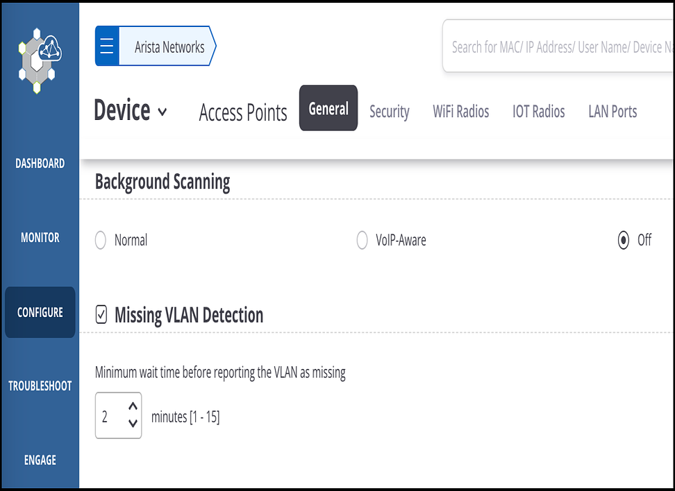
Configure Missing VLAN Detection
Network Administrators can see missing VLANs in the network to diagnose and resolve the issue quickly. Sometimes out-of-the-box Access Points (APs) cannot send and receive traffic through the switchport they are connected to because the Switch doesn’t have the same VLAN as the AP. This issue could be time-consuming to diagnose and identify as Network Administrators follow a series of error elimination steps to determine the root cause. After the administrator identifies the root cause, the fix is trivial; they only need to create the missing VLANs in the Switch network.
Configure Missing VLAN
Configure the missing VLAN in Device Settings, and the configuration will be pushed to all the APs in the given location.
- Go to
- Select the General tab and move through to the Missing VLAN Detection section.
- Select the Missing VLAN Detection checkbox and specify the minimum
wait time to report a missing VLAN. When the AP does not detect any activity
on a VLAN, it waits for the specified duration before considering it a
missing VLAN.
Monitor Missing VLAN
- AP ListingYou can monitor missing VLANs from the AP listing from MONITOR > WiFi > Access Points. The three new columns—Missing VLAN, Missing Bridge VLAN, and Missing Tunnel VLAN—provide all the information regarding the missing VLANs.

When selecting the AP from the AP listing, the Wired Properties section shows the missing VLANs—missing Tunnel and Bridge VLANs. The missing VLAN is also seen when hovering on the data path.
- Wired Properties
The Wired Properties section in the right panel displays the list of missing VLANs.
Right-click the AP from the AP listing and select View Properties to open the right panel.
Configure Inter Access Point Sync for Client Steering in Device Settings
Inter Access Point Sync if enabled syncs with neighboring APs to share client visibility information for an improved steering experience.
You should enable inter Access Point sync for multiple AP deployments only. Background scanning must be turned on all AP radios except for the devices with 3rd scanning radio.
- Navigate to
- Click Client Steering Common Parameters from the bottom panel.
- Select Inter-Access Point Sync for Client Steering.
- Enter Sync Period in seconds.
Info:Sync Period is the time interval specified to broadcast periodic Sync messages. The time interval can be minimum 10 seconds and maximum 60 seconds.
- Click Save.
Configure Client RSSI Update Interval in Device Settings
This feature provides Client RSSI Update after every specific interval.
- Navigate to .
- Scroll down to Client RSSI Update Interval section.
- Enter the interval value in seconds.
- Click Save.
Configure VLAN Extension in Device Settings
Enabling VLAN Extension takes precedence over the Wired Extension configured in the Network Profile in SSID settings.
To configure VLAN Extension:
- Navigate to .
- Select VLAN Extension.
- Select the LAN port and specify the VLAN ID. The applicable values are 0 through 4094, where 0 indicates an untagged VLAN. A LAN port can be mapped to only one VLAN ID. But, the same VLAN ID can be mapped with more than one LAN port.
- Save the settings.
Configure Link Aggregation in Device Settings
Enabling Link Aggregation allows multiple ports to merge logically in a single link. This leads to minimizing the wastage of bandwidth as the full bandwidth of each physical link is available. Link aggregation offers higher aggregate bandwidth on servers having heavy traffic.
If you enable Link Aggregation for the device, the Enable Wired Extension option in the SSID profile, if set, will be ignored and not take effect.
- Navigate to .
- Select Link Aggregation.
- Select the Transmit Hash Policy.You can choose from
one of the following options to define the transmit hash policy:
- Layer 2 (MAC)
- Layer 3+4 (IP+Port)
- Layer 2+3 (MAC+IP)
Note: If you enable link aggregation, then you must use a switch that is capable of link aggregation.
- Save the settings.
Configure LAN1 as Preferred Primary Uplink
LAN1 is considered the primary Uplink Port. Enable the Prefer Primary (LAN1) option to switch to LAN1 whenever available. When enabled, if LAN2 is in use and LAN1 becomes available, AP will immediately switch to LAN1; it will not wait for LAN2 to be down or unavailable before switching to LAN1. If both the LAN Ports are available, the AP will always use LAN1 when this option is enabled.
- Navigate to .
- Select Prefer Primary(LAN 1).
- Save the settings.
Configure and Monitor Alerts
Configure the AP Uplink Port switched alert to notify you of a switchover in the LAN port. Enable the alert from CONFIGURE > Alert > Device > AP Uplink Port switched.
ConfigureAeroScout Integration
- Make sure the APs at the locations where you want Aeroscout to work are broadcasting at least one SSID on the 2.4 GHz band. AeroScout tags use this band to communicate with Wi-Fi APs. You can set up SSIDs under
- To enable integration with AeroScout, go to tab. In the Integrations section, select the AeroScout checkbox
and set the port number (1144) to be used for the AP-AeroScout communication.Note: Make sure that the port (1144) is open for bidirectional UDP communication between the AES and the APs.
- Make sure that APs at this location use only channels 1, 6, and 11 on the 2.4 GHz band. AeroScout tags typically use these channels to communicate with Wi-Fi APs. You can configure Channel Settings under
Configure Antenna Settings in Device Settings
This configuration is applicable for C-50, C-60, C-10, SS-200-AT-01. User can select internal or external antenna depending on preferences.
- Navigate to
- Scroll down to Legacy Model Features.
- Select the Antenna Type. This field has 2 values-internal and external. If you want to work with internal antennas, select Internal. If you want to work with external antennas, select External.
- Click Save.
Configure Device Password in Device Settings
Device Password configuration helps you manage the password for Arista Access Points. By defining a password in this setting, you can manage the password for a group of devices without having to change it on each device separately.
- Navigate to
- In the Device Password section, enter your username. The default username is config.
- Enter the password. The password must contain at least eight characters, it cannot contain your login ID, and you cannot provide the last three passwords.
- Re-enter your password for confirmation.
- Save the settings.
Send Client and Access Point Logs to Syslog Server
Send logs of Access Points (AP) and clients securely to a remote Syslog server. On enabling Secure Remote Syslog, the AP sends the logs securely to the Syslog server using the TLS protocol through port 6514. This functionality is useful for audit purposes.
APs support TLS 1.2 and higher for communication.
Note: If you do not select the Secure Remote Syslog checkbox, the AP connects to the Syslog server on UDP port 514, which is the default Syslog communication mode.
You can also verify the Syslog server’s identity by enabling the Verify Syslog Server’s Certificate checkbox and uploading its CA Certificate. If you don’t want to verify the Syslog server’s identity, the AP can still connect using the Syslog server's certificate without any verification or authentication.
- Navigate to .
- Navigate to the Network section and expand it.
- Select .
- Select the AP Certificate Tag from the dropdown list. AP Certificate tags are required to establish a secure connection.
- Select Verify Syslog Server’s Certificate and add the Syslog server’s CA Certificate.
- Save the settings.
Configure IPv4/IPv6 Dual Stack in Device Settings
You can enable or disable the support for IPv4/IPv6 dual stack network. When you enable support for IPv4/IPv6 dual stack network, the AP, to which the device settings are applied, is able to operate on both IPv4 and IPv6 addresses simultaneously. When you disable support for IPv4/IPv6 dual stack network, the AP, to which the device template is applied, can operate on IPv4 networks only.
- Navigate to
- Select IPv4/IPv6 Dual Stack in the Network section.
- Click Save.
Enable SSH IP Allow List
The Enable SSH IP Allow List option under the Device Settings tab is unchecked by default. You can enforce SSH access from specific IP addresses by checking this option. If this option is enabled, only IP addresses that match the specified criteria can SSH to the AP.
- Navigate to tab.
- Select Enable SSH IP Allow List in the Network section.
- Enter an IPv4 IP address in the IP Address field.
- Enter a Wildcard Mask. in the Wildcard Mask fileld.
- Click Add.
SSH IP Allow List Parameters
| Field | Description |
|---|---|
| IP Address | A valid IP address. |
| Wildcard Mask | The wildcard mask is a mask of bits that helps identify the parts of the IP address that must match and the parts that can be ignored. The binary equivalent of the IP address and wildcard mask is used for examining the bits that must match. Wildcard mask acts as an inverted subnet masks, i.e, the zero bits in the mask indicate that the corresponding bit position in the IP addresses must match. The one bits indicate that the corresponding bit position does not have to match. For example: if the IP address is 10.10.0.0 and the mask is 0.0.0.255 then the IP addresses 10.10.0.0 through 10.10.0.255 will match. However, if the mask is 0.0.1.255 then the IP address 10.10.0.0 through 10.10.0.255 and 10.10.1.0 through 10.10.1.255 will match. |
Enable Multiple VLAN Registration Protocol
Multiple VLAN Registration Protocol (MVRP) is a Layer 2 protocol. The protocol allows access points to propagate the VLAN created on CV-CUE to the connected Switches. The real-time propagation of configuration allows you the flexibility of configuring your wired and wireless network in one interface and distributing it to other active interfaces. You do not have to worry about managing and maintaining the configurations in all interfaces.
- Before enabling MVRP on CV-CUE, ensure that MVRP is enabled on the Switch interface. Refer to the vendor-specific Switch documentation for more information on enabling MVRP on Switches.
- The AP reboots every time you update the MVRP configuration in CV-CUE.
- MVRP is not supported for non-root AP in a Mesh network.
- Navigate to tab and scroll-down to Network section.
- Select the Enable MVRP checkbox.
- Save the settings.
Configure NTP in Device Setting
The Arista device system clock resets itself to Epoch time (that is, January 1, 1970) after every reboot as it does not have an internal battery to maintain time across reboots. The system clock is used to timestamp the logs. You can ensure that the timestamp on the logs reflect the correct date and time by synchronizing the Arista device system clock with an NTP server. This can be done by specifying the details of the NTP server for Arista device time synchronization under device settings.
- Navigate to tab.
- Scroll down to NTP Configuration in Network section.
- Enter Primary NTP Server
IP/Hostname.
Info:The default primary NTP server is the NIST (National Institute of Standards and Technology) NTP server, time.nist.gov. The NIST NTP server is a server cluster maintained by the US federal government and is connected to high precision atomic clocks. The NIST NTP server is accessible from almost every corner of the globe.
- Enter Secondary NTP Server IP/Hostname. The Arista device synchronizes time with the secondary NTP server, if specified, when the primary NTP server is unavailable or inaccessible. It is not mandatory to specify the secondary NTP server.
- Click Save.
Configure Maximum Transmission Unit
Arista Access Points (AP) support configuring the Maximum Transmission Unit (MTU) to send large packets without fragmentation. The default MTU is 1500 bytes.
Introduction
Arista Access Points (AP) support configuring the Maximum Transmission Unit (MTU) to send large packets without fragmentation. The default MTU is 1500 bytes.
MTU configuration is supported for IPv6 and IPv4. MTU configuration applies to the Bridge and Network VLAN. It's not available for Tunnel VLAN.
It is an AP-level setting and applies to all APs at a location.
The MTU calculation and its impact across the network is explained in Jumbo Frame Support on Arista Access Points.
Configuring MTU
Follow these steps:
- Go to .
- Navigate to the Network section, expand it, and select
Maximum Transmission Unit.
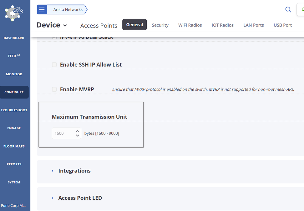
- Enter your MTU size. The supported range is 1500 to 9000 bytes.
- Save the settings.
Additional Information
Jumbo Frame Support on Arista Access PointsConfigure Access Radio Exceptions in Device Settings
Access Radio Exception is configured for Single Radio or Dual Radio devices. This configuration helps devices to choose the frequency band in case of model agnostic configuration.
- Navigate to
- Scroll down to Legacy Model Features.
- Select the type of AP between Single Radio AP and
Dual Radio AP-Sensor Combo for which
configuration is to be done.
- If you have a single radio AP, then select the frequency band on which your AP should operate below Single Radio AP tab.
- If you have a dual-radio AP that can operate as an AP and Sensor, then select the frequency band for an AP to operate.
- Click Save.
Device Security Settings
On the Security tab under Device Settings, you can configure VLAN Monitoring and WIPS.
It is really easy to set up an unauthorized Wi-Fi network. Small plug-and-play devices can act as access points. Smart phones and tablets can act as Wi-Fi hotspots. Clients can connect to any such access point or hotspot and easily access a network that is not adequately protected against wireless threats. In this way, a network could easily become vulnerable to wireless attacks. It is therefore important to understand and control authorized and unauthorized access to Wi-Fi networks. A good Wireless Intrusion Prevention System (WIPS) is a must to prevent unauthorized access to a network.
Arista’s AP have in-built WIPS solution that can automatically classify devices to detect rogues, and prevent rogue devices from accessing your Wi-Fi network.
You can enable Offline Mode and select the channels to monitor and defend. The Offline Mode feature provides some security coverage even when there is no connectivity between an Arista AP and the server. Offline Mode applies only to an Arista AP functioning as a sensor. In the Offline Mode, the sensor of the AP continues to provide a certain-level of device classification and prevention, even when it is disconnected from the server. The sensor also raises events, stores them, and pushes them back to the server on re-connection.
You can select the channels to monitor for WIPS detection and the channels to defend for WIPS prevention.
How Auto VLAN Monitoring Works
Virtual Local Area Network (VLAN) Monitoring allows you to monitor devices on a VLAN and clients associated with these devices. Arista AirTight, Arista’s patented Wireless Intrusion Prevention System (WIPS) solution, automatically classifies devices on the monitored VLAN as Authorized, Rogue or External.
- SSID VLAN Monitoring: APs monitor their SSID VLANs.
- Auto VLAN Monitoring: APs automatically monitor any VLAN on which they detect activity.
- Additional VLANs: Additional VLANs to be monitored by APs in that folder or group.
These settings apply to the folder (location) or group. In enterprise Wi-Fi deployments, each AP can often see a different set of VLANs. In such cases, you can define custom VLANs to be monitored on a per-AP basis (under as described in the Monitoring WiFi > Access Points section.
SSID VLAN Monitoring is enabled by default. You can disable it if you do not want the AP to monitor VLANs corresponding to the SSIDs configured on the AP.
Number of VLANs Monitored
| Model | AP Mode | Sensor Mode | ND Mode |
|---|---|---|---|
| C-50 | 12 | 16 | 50 |
| Other Arista devices | 20 | 20 | 100 |
- Communication VLAN: By default, an AP monitors the VLAN it uses to communicate with CV-CUE.
- SSID VLANs: If SSID VLAN Monitoring is enabled, an AP monitors its SSID VLANs.
- Per-AP VLANs: If customized VLANs are configured for monitoring on a particular AP, then the AP monitors these custom VLANs.
- Additional VLANs: VLANs configured for monitoring (under Device Settings) for the folder (location) or group.
- Auto VLAN Monitoring: If Auto VLAN Monitoring is enabled, an AP monitors any VLANs (other than the ones already being monitored) on which it detects activity.
If an AP reaches the maximum number of VLANs it can monitor, then the order listed above determines which VLANs the AP monitors and which ones it does not.
- When SSID VLAN Monitoring is enabled, the number of VLANs that an AP automatically monitors is equal to the maximum number it can monitor minus the sum of the number of SSID VLANs and user-defined VLANs. (User-defined VLANs include per-AP VLANs and additional VLANs for the folder or group.)
- Number of automatically monitored VLANs = Max – (SSID VLANs + User-Defined VLANs)For example, a C-120 in AP mode can monitor a maximum of 20 VLANs. If there are 4 SSID VLANs and 2 user-defined VLANs, the number of automatically monitored VLANs is: 20 - (4+2) = 14.
- When SSID VLAN Monitoring is disabled, the number of VLANs that an AP automatically monitors is equal to the maximum number it can monitor minus the number of user-defined VLANs. Number of automatically monitored VLANs = Max – User-Defined VLANs.
Configure BLE Settings
Bluetooth Low Energy (BLE) is used for proximity based services on mobile devices via an application ecosystem. Arista APs support the iBeacon BLE standard.
- UUID - This identifies the beacon. It is defined for a Location in the Arista Location Hierarchy. The default value of the UUID is a pre-defined random string at the Root location. You can keep this value or generate a new one.
- Major - This is a number that identifies a subset of beacons within a large group.It is defined for a Location in the Arista Location Hierarchy. Its range is from 0 - 65535.The default value is 0.
- Minor - This is a number that identifies a specific beacon. It is defined at a device level. Its range is from 0 - 65535.The default value is 0.
- Advertising Interval - This is the periodic interval at which beacons are transmitted.
The UUID and Major values are defined at a location in the Arista location hierarchy. For child locations, you can copy the values of these parameters from the parent locations. The Minor and Advertising Interval values are configured in the device settings for an AP.
For details on which APs support BLE, see the BLE Support article on the Wi-Fi Help portal.
Example Use Case for BLE
Let us consider a retail store chain with outlets at two locations - Westside and Eastside. You can then generate different UUID's for iBeacons in each location, i.e., one for Westside and one for Eastside. Within each location, you can further define different Minor values for APs based on the department / aisle within the store - for example, you can have different Minor values for APs in the food and clothing sections. The application ecosystem that you use to provide proximity based services can then use these values to offer location-appropriate options to customers in the store.
Configure BLE from Device Settings
Configure BLE involves configuring UUID, Major, Advertising Interval and Minor. The BLE UUID and Major are defined at a location level. Advertising and Minor are defined at device level.
- Go to
- Click IOT Radios tab.
- To configure BLE UUID and Major, click the Set UUID and Major
link.
- Select the location where you want to set the BLE parameters and click Next.
- Enter the UUID or click Generate UUID to generate one.
- Enter a value for the Major number.
- Click Save.
- To configure Advertising Interval and Minor, select Bluetooth Low
Energy (BLE) to enable BLE.
- Enter the Advertising Interval.
- Enter a value for the Minor number.
- Save the Device Settings.
Customize the BLE Minor of an Access Point
- Go to
- Right-click the AP for which you want to configure the BLE Minor and select Customize BLE.
- Select Bluetooth Low Energy (BLE) to enable BLE on this AP.
- Enter a value for the Minor number.
- Save the settings.
Configure Bluetooth Scanning
You can configure Bluetooth scanning to detect nearby Bluetooth devices.
- Navigate to
- Under the IOT Radios tab, select Bluetooth Scanning checkbox.
Scanned Bluetooth Devices
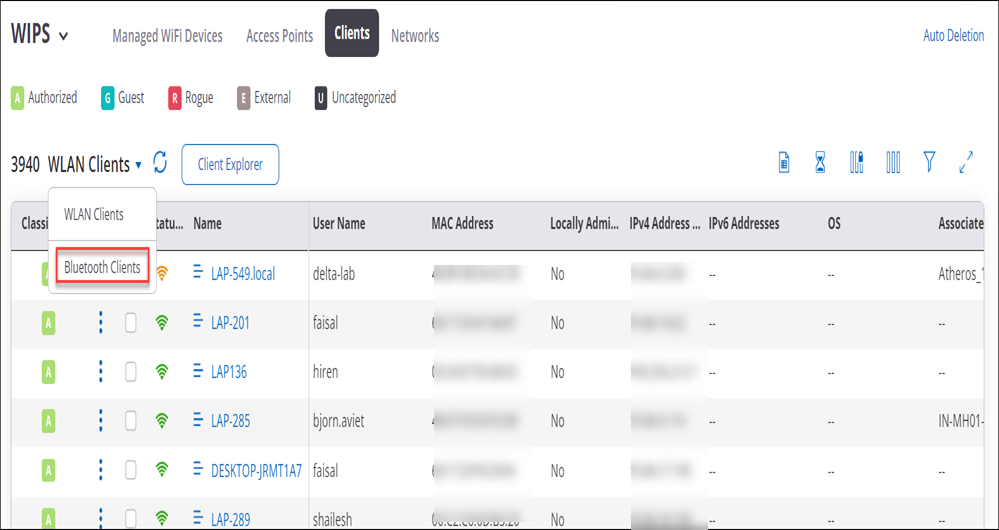
Detected Bluetooth devices are displayed in a grid as follows:
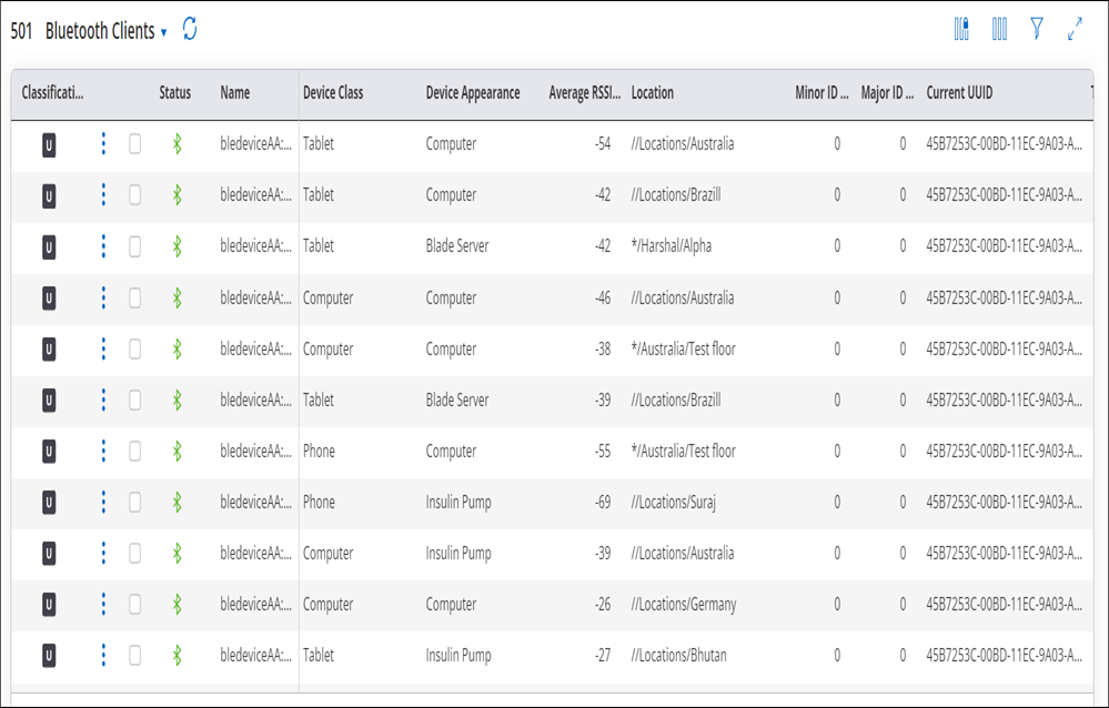
- Classification: By default, Bluetooth devices are classified as Uncategorized. You can authorize a Bluetooth client by classifying it as Authorized.
- Rename: You can rename Bluetooth devices. You can also rename multiple Bluetooth devices at once. Note: You can rename authorized devices only.
- Delete: You can delete identified Bluetooth devices. Note: You can delete authorized and inactive devices only. When the deleted device is detected next time, it will be classified as Uncategorized.
Send Analytics to Third-Party Server
You can send information about visible Bluetooth devices such as MAC address and RSSI, and timestamp to third-party servers. This may be used by 3rd party systems, e.g. to determine client location using RSSI triangulation.
- Select Push Analytics to Third-Party Server checkbox under Bluetooth Scanning.
- Enter values for the following fields and save your device settings.
- Visibility Analytics Format: You can send the data as a CSV file or a JSON file.
- Server URL: Enter the URL of the third-party server to send data.
- Send Interval: Enter the time interval to send the data.
- Authorization: Enter the authorization details for the third-party server. You can enter the Key or User Name and Password.
Configure Uplink Port Authentication for Access Point
You can authenticate edge devices from a centrally managed network access control server using the 802.1X authentication. As a network administrator, you want to authenticate the access points (APs), before the APs connect to the network. To enable the authentication, you need to first configure the uplink port on the AP using CV-CUE.
The uplink port authentication is supported only on the eth0 port of the AP.
- All switches supporting the 802.1X protocol (multi-host mode)
- All Wi-Fi 6 and higher version APs
Workflow
A new access point (AP) does not have the 802.1X configuration. When you connect a new access point to the switch via the uplink (eth0) port, the switch assigns a Guest VLAN (temporary VLAN) to the AP for that particular location. The AP uses the Guest VLAN to connect to CV-CUE and download the necessary configurations. Once the AP receives the configuration for uplink port authentication, the AP becomes capable of sending EAPOL frames. It removes the Guest VLAN and does uplink port authentication.
Further, the RADIUS server assigns a Native VLAN or Auth-Fail VLAN based on the authentication result.
The uplink port authentication is location-specific. If you change the location of the AP, it goes through a re-authentication process. The 802.1X network uses the EAP-TLS protocol for digital authentication.
For more information on Configuring 802.1X on the Switch Port, refer to Uplink Port Authentication for Access Point.
Prerequisites
- CA certificate of the RADIUS server
- Device certificates, which are managed using tags
- Navigate to tab.
- Enable the Uplink Port Authentication check box.
- Select the Authentication Method as TLS (eap-tls).
- Select the certificate tag from the Client Certificate Tag drop-down list.
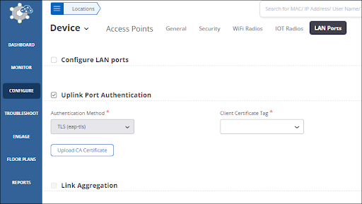
- Click Upload CA Certificate and upload the CA certificate of the RADIUS server from your local drive.
- Save the settings.
When Uplink Port Authentication is enabled, the Link Aggregation check box is disabled. That’s because link aggregation is not supported for uplink port authentication. Similarly, if you have enabled Link Aggregation for a location, you cannot enable Uplink Port Authentication.
Verify Configuration
You can verify whether the uplink port authentication is enabled successfully from
the Managed WiFi Devices tab in
MONITOR
> Wired. 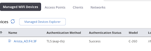
You can also configure alerts to notify you for any authentication failure.
You can view the alerts from

Configure VLAN Monitoring in Device Settings
VLAN monitoring is essential for the wired-side connection status detection, host name detection, smart device detection, rogue AP detection, and so on.
- Configured as WIPS sensors
- Configured in the AP mode and have Background Scanning enabled and Wireless Security Features enabled
- Multi-radio devices.
- Navigate to .
- In the VLAN Monitoring section, select Auto VLAN Monitoring to automatically monitor the VLANs.
- Select Monitor Additional VLANs to enable the device to monitor additional VLANs.
- Enter the additional VLANs to be monitored as a comma-separated list.
- Click Save.
VLAN Monitoring Parameters
| Field | Description |
|---|---|
| Auto VLAN Monitoring | Parameter to
automatically monitor the VLANs that are added by the SSID,
configured through additional VLANs or through CLI. The behavior
of the automatically monitored VLANs is as follows:
|
| Monitor Additional VLANs | Parameter to enable the device to monitor additional VLANs. |
| Comma separated list of VLAN IDs | The VLAN used by
the device to communicate with the server is always monitored and
need not be specified here. VLAN IDs can be between 0 to 4094. The
additional VLANs to be monitored must be configured on the switch
port where the device is connected and must be DHCP enabled. A VLAN
ID '0' indicates untagged VLAN on the switch port where the device
is connected, irrespective of the actual VLAN number on the switch.
Important:If a VLAN is configured with a static IP
address, then configure the VLAN from the CLI.
|
Configure WIPS Settings in Device Settings
In Device Settings while configuring WIPS Settings, you can enable Offline Mode features as well as you can set channels to monitor and defend intrusion under Channel Settings.
- Navigate to
- Go to Security tab.
- Select Offline Mode.
- Enter time in minutes to state the time constraint after which device should switch to offline mode after it detects loss of connectivity.
- Select Channels To Monitor from Channel
Settings to select the list of channels for monitoring
intrusion.
Info:You can optionally select Select All Standard Channels, Select all Allowed Channels and Additionally, select intermediate channels.
- Select Channels to Defend from Channel
Settings to select the list of channels for defending
intrusion.
You can optionally select Select All Standard Channels and Select all Allowed Channels
- Click Save.
WIPS Settings Parameters
The below table contains detail information about the parameters included in WIPS Settings.
| Field | Description |
|---|---|
| Offline Mode | This feature provides
some security coverage even when there is no connectivity between an
Arista device and the server. The feature is relevant to an Arista
device functioning as a sensor. The sensor provides some device
classification and prevention capabilities when it is disconnected from
the server. The sensor also raises events, stores them, and pushes them
back to the server on reconnecting. You can specify the time, in minutes, for the device to switch to offline mode after the device detects loss of connectivity from the server. (Minimum: 1 minute; Maximum: 60 minutes; Default: 15 minutes). |
| Channel Settings | List of channels for the sensor to monitor and defend intrusion. These channels will differ according to your country of operation. Refer to the following table for the channel number, its protocol and respective frequency. |
| Channels To Monitor | List of channels to be selected to monitor intrusion. |
| Channels to Defend | List of channels to be selected to defend intrusion. |
| Select All Standard Channels | It auto selects all the standard channels. |
| Select all allowed channels | It auto selects all the allowed channels |
| Additionally, select intermediate channels |
| Channel | Protocol | Frequency (GHz) |
|---|---|---|
| 1 | b/g/n | 2.412 |
| 2 | b/g/n | 2.417 |
| 3 | b/g/n | 2.422 |
| 4 | b/g/n | 2.427 |
| 5 | b/g/n | 2.432 |
| 6 | b/g/n | 2.437 |
| 7 | b/g/n | 2.442 |
| 8 | b/g/n | 2.447 |
| 9 | b/g/n | 2.452 |
| 10 | b/g/n | 2.457 |
| 11 | b/g/n | 2.462 |
| 12 | b/g/n | 2.467 |
| 13 | b/g/n | 2.472 |
| 14 | b/g/n | 2.487 |
| 184 | a/n/ac | 4.92 |
| 188 | a/n/ac | 4.94 |
| 192 | a/n/ac | 4.96 |
| 196 | a/n/ac | 4.98 |
| 208 | a/n/ac | 5.04 |
| 212 | a/n/ac | 5.06 |
| 216 | a/n/ac | 5.08 |
| 34 | a/n/ac | 5.17 |
| 36 | a/n/ac | 5.18 |
| 38 | a/n/ac | 5.19 |
| 40 | a/n/ac | 5.2 |
| 42 | a/n/ac | 5.21 |
| 44 | a/n/ac | 5.22 |
| 46 | a/n/ac | 5.23 |
| 48 | a/n/ac | 5.24 |
| 50 | a/n/ac | 5.25 |
| 52 | a/n/ac | 5.26 |
| 56 | a/n/ac | 5.28 |
| 56 | a/n/ac | 5.28 |
| 58 | a/n/ac | 5.29 |
| 60 | a/n/ac | 5.3 |
| 64 | a/n/ac | 5.32 |
| 100 | a/n/ac | 5.5 |
| 104 | a/n/ac | 5.52 |
| 108 | a/n/ac | 5.54 |
| 112 | a/n/ac | 5.56 |
| 116 | a/n/ac | 5.58 |
| 120 | a/n/ac | 5.6 |
| 124 | a/n/ac | 5.62 |
| 128 | a/n/ac | 5.64 |
| 132 | a/n/ac | 5.66 |
| 136 | a/n/ac | 5.68 |
| 140 | a/n/ac | 5.7 |
| 149 | a/n/ac | 5.745 |
| 152 | a/n/ac | 5.76 |
| 153 | a/n/ac | 5.765 |
| 153 | a/n/ac | 5.765 |
| 157 | a/n/ac | 5.785 |
| 160 | a/n/ac | 5.8 |
| 161 | a/n/ac | 5.805 |
| 161 | a/n/ac | 5.805 |
| 165 | a/n/ac | 5.825 |
Send Device Analytics to a Third-Party Server
An Arista Access Point (AP) can send Received Signal Strength Indicator (RSSI) values of associated and unassociated visible Wi-Fi clients, and neighboring Arista APs to an external third-party server. The data shared with a third-party server include:
- LAN MAC of the neighboring Arista AP or client
- RSSI value
- Band: 2.4, 5, or 6 GHz
- Time stamp
- Type: client or AP
- Transmit channel
The AP sends this data as a JSON or CSV file at a recurring interval that you can configure.
- Select the location at which you want APs to send analytics information to third-party servers.
- Go to .
- Scroll down and select the Push Visibility Analytics to Third-Party Server check box.
- Configure the fields shown in the following table:
Field Description Visibility Analytics Format You can view the analytics data in CSV or JSON format. Server URL The URL of the third-party server. Authorization You can choose the authorization mechanism used by the AP to communicate with the third-party server. Provide either an authorization key, or a username and password. Send Interval The interval in seconds at which the AP sends RSSI values to the server. - Save the settings.
Configuring SESimagotag Retail IoT Connector with Arista APs
This feature is supported on C-360, C-330, C-260, and C-250 AP models.
|
AP Model |
Recommended power mode |
|---|---|
|
C-250 |
802.3bt |
|
C-260 |
802.3bt |
|
C-360 |
802.3bt |
|
C-330 |
802.3at |
Steps to Integrate SESimagotag ESLs with Arista AP
Perform the following steps to integrate SESimagoTags with Arista AP:
- Connect the SESimagoTag dongle to Arista AP
- Configuring Arista APs in VusionCloud
-
Configure the dongle details in CV-CUE
- Importing and connecting ESLs to the dongle
- Configuring Individual ESLs in VusionCloud
- Pushing the product image on the ESL
For information on VUSIONCloud Configuration and pushing product images, refer to https://arista.my.site.com/AristaCommunity/s/article/Integrating-SESimagotag-Retail-IoT-Connector-with-Arista-APs.
Connecting the SESimagotag dongle to the Arista AP
We recommend using a 3-meter cable to connect the SESimagotag IoT dongle to Arista AP to avoid interference with Bluetooth operations.
- Navigate to CONFIGURE > Device > Access Points.
- Go to the USB Port tab. Select SESimagotag.
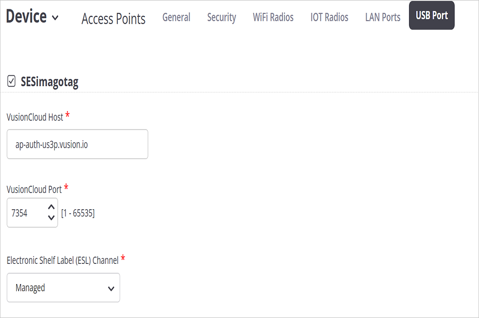
-
Enter the following information:
- VusionCloud Host: URL of the VusionCloud instance to which the AP can connect.
- VusionCloud Port: 7354
- Electronic Shelf Label(ESL) Channel: Managed
VusionCloud controls the selection of ESL Channels.
- Click Save.
After the AP detects the dongle and you save this configuration, SCD Daemon connects the AP to VusionCloud.
Verification of AP’s Connection to VusionCloud


Access Point ID: This is the unique ID of the Imagotag USB dongle.
Customize Device Attributes for Location Specific Overrides
Network Administrators can configure device settings at any location in CV-CUE, and the child location inherits all the configuration from the parent location. Administrators can override certain attributes of a device configuration at a child location without breaking inheritance, so that the entire device configuration remains unchanged except for the overridden attributes.
Overriding device attributes is useful if you want to have the same configurations across your organization but want to have specific attributes for specific locations. This ensures your global network policies remain consistent while allowing for local variations, such as time zones (NTP) or local wireless regulations.
Overriding device attributes is not supported for Groups.
Note: This feature applies only to locations that inherit configurations from a parent. Locations with existing custom configurations do not support device attribute overrides.- NTP Configuration
- Device Password
- Regulatory Domain
- Wi-Fi Radios Candidate Channels
- Wi-Fi Radios Channel Width
- Wi-Fi Radios Transmit Power Selection
Overriding Device Attributes and Restoring Inheritance
- Select the location and then select .
Alternatively, you can click the three-dot menu on the screen. The General tab displays the current attributes of the parent and child locations.
- Click the pencil icon to edit it. Under the General tab,
you can modify the following attributes: NTP Configuration, Device Password, and
Regulatory Domain.Important: Changing RF Regulatory Domain will reset Candidate Channels and Security Channel settings to the new domain's defaults. Save the Regulatory Domain overrides independently. Do not combine a Regulatory Domain change with other attribute overrides in a single save request.
- Select the Radios tab and modify the following
attributes: Channel Selection and Transmit Power Selection.Note: Channel Selection and Transmit Power Selection must be set to auto in the parent location.
You see a table comparing the device attributes of the current folder and its parent folders side-by-side.
- Save the changes by clicking the Save icon (check mark icon).
Attributes marked with an asterisk (*) indicate settings that have been overridden at the child level and are no longer inheriting values from the parent configuration.
Restoring Inheritance
If you want to remove an override and return to the parent's settings, click the Inherit from Parent icon next to the overridden attribute.