Data Transfer
Arista switches support the transfer of packets (network layer) and frames (data link layer). This chapter describes concepts and processes that are referenced by routing and switching protocols that Arista switches support.
Data Transfer Introduction
Arista switches transfer data through switching, routing, and Layer 3 switching. This chapter provides an introduction to these transfer methods.
- routed ports
- switched ports
- MAC address table
- port mirroring
- storm control
- loopback interfaces
- route redistribution
- null0 interfaces
- MTUs
Data Transfer Methods
Switching and Bridging
Switching and bridging operations transmit data link layer frames between devices within a single subnet. Each port is assigned a 48 bit Media Access Control (MAC) address. Frames arriving at a hub are bridged, or sent to all other ports on the subnet. Switches can associate ports with their MAC addresses, obviating the need to flood the subnet when sending a frame.
Subnets in the switch are defined by VLANs. A Virtual Local Area Network (VLAN) is a group of devices that are configured to communicate as if they are attached to the same network regardless of their physical location. VLANs describes VLANS.
- unicast: represents a single interface.
- broadcast: represents all interfaces.
- multicast: represents a subset of all interfaces.
- reserved: assigned to nodes that have no configured MAC address.
The Individual/Group (I/G) bit distinguishes unicast MAC addresses from multicast addresses. As shown in Figure 1 , the I/G bit is the least significant bit of the most significant byte in a MAC address.
MAC Address Format
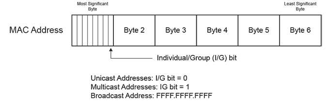
- Unicast address: the I/G bit is 0:
1234.1111.1111 is a unicast MAC address (the
most significant byte is an even number).
- Reserved address: all bits set to 0 (0000.0000.0000).
- Multicast address: the I/G bit is 1: 1134.1111.1111 is a multicast MAC address (the most significant byte is an odd number).
- Broadcast address: all bits set to 1 (FFFF.FFFF.FFFF).
Examples
- The following are unicast MAC addresses:
0200.0000.0000 1400.0000.0000 - The following are multicast MAC addresses:
0300.0000.0000
2500.0000.0000
Routing
Routing transmits network layer packets over connected independent subnets. Each subnet is assigned an IP address range and each device on the subnet is assigned an IP address from that range. Connected subnets have IP address ranges that do not overlap. A router connects multiple subnets. Routers forward inbound packets to the subnet whose address range includes the packets’ destination address.
IPv4 and IPv6 are internet layer protocols that facilitate packet-switched networking, including transmissions across multiple networks.
Static Routing
Static routes are entered through the CLI and are typically used when dynamic protocols are unable to establish routes to a specified destination prefix. Static routes are also useful when dynamic routing protocols are not available or appropriate.
Creating a static route associates a destination IP address with a local interface. The routing table refers to these routes as connected routes that are available for redistribution into routing domains defined by dynamic routing protocols.
Dynamic Routing
Dynamic routes are established by dynamic routing protocols. These protocols also maintain the routing table and modify routes to adjust for topology or traffic changes. Routing protocols assist the switch in communicating with other devices to exchange network information, maintaining routing tables, and establishing data paths.
Layer 3 Switching
Layer 3 switches establish data paths through routing processes (Layer 3) and transfer data as a switch (Layer 2) through speed-optimized hardware. Layer 3 switches use a control plane (routing) and data plane (switching) to manage these processes.
Control plane
The control plane builds and maintains the IP routing table, which identifies IP packet routes in terms of destination addresses. The routing table defines a route by its next hop address and the egress interface that accesses the next hop.
- Status of physical and virtual interfaces on the switch.
- Static routes entered through the CLI.
- Routes established through dynamic routing protocols.
Applying an ACL to the Control Plane
The control plane supports routing and management functions, handling packets that are addressed to the switch without regard to any switch interface.
To apply an IP ACL to the control plane, enter ip access-group (Control Plane mode) in control-plane mode. The system control-plane command places the switch in control-plane mode.
ACLs and Route Mapsdescribes access control lists.
Example
switch(config)# system control-plane
switch(config-system-cp)# ip access-group CP-Test1 in
switch(config-system-cp)#
Data plane
The data plane routes IP packets based on information derived by the control plane. Each packet’s path includes Layer 2 addresses that reach its next hop destination. The data plane also performs other operations required by IP routing, such as recalculating IP header checksums and decrementing the Time-To-Live (TTL) field.
- Store and forward: the switch accumulates entire packets before forwarding them.
- Cut through: the switch begins forwarding frames before their reception is complete.
Cut through mode reduces switch latency at the risk of decreased reliability. Packet transmissions can begin immediately after the destination address is processed. Corrupted frames may be forwarded because packet transmissions begin before CRC bytes are received.
- Arad: store and forward mode only.
- FM6000: both modes are available.
- Petra: store and forward mode only.
- Trident: both modes are available.
- Trident II: both modes are available.
The data plane is also referred to as the forwarding plane.
Data Plane Forwarding Mode Configuration
The switch forwarding-mode command specifies the forwarding mode of the switch's data plane. This command is available on Trident, Trident II, and FM6000 platform switches. The forwarding mode is store-and-forward on Arad and Petra platform switches.
Examples
- This command changes the forwarding mode to
store-and-forward.
switch(config)# switch forwarding-mode store-and-forward switch(config)# - The show switch
forwarding-mode command displays the switch’s forwarding
mode.
switch(config)# show switch forwarding-mode
Current switching mode:    store and forward
Available switching modes: cut through, store and forward
MAC Address Table
- Enter static MAC addresses into the table through a CLI command.
- Dynamic MAC addresses enter into the table when the switch receives a frame whose source address not listed in the MAC address table. The switch builds the table dynamically by referencing the source address of received frames.
MAC Address Table Configuration
Static MAC Address Table Entries
- A drop entry does not include a port.
- A unicast entry includes one port.
- A multicast entry includes at least one port.
Packets with a MAC address (source or destination) and VLAN specified by a drop entry are dropped. Drop entries are valid for only unicast MAC addresses.
The mac address-table static command adds a static entry to the MAC address table.
Examples
- This command adds a static entry for unicast MAC address
0012.3694.03ec to the
MAC address
table.
switch(config)# mac address-table static 0012.3694.03ec vlan 3 interface Ethernet 7 switch(config)# show mac address-table static Mac Address Table ------------------------------------------------------------------ Vlan Mac Address Type Ports Moves Last Move ---- ----------- ---- ----- ----- --------- 3 0012.3694.03ec STATIC Et7 Total Mac Addresses for this criterion: 1 Multicast Mac Address Table ------------------------------------------------------------------ Vlan Mac Address Type Ports ---- ----------- ---- ----- Total Mac Addresses for this criterion: 0 switch(config)# - This command adds the static entry for the multicast MAC
address 0112.3057.8423
to the MAC address
table.
switch(config)# mac address-table static 0112.3057.8423 vlan 4 interface
port-channel 10 port-channel 12
switch(config)# show mac address-table
          Mac Address Table
------------------------------------------------------------------

Vlan    Mac Address       Type        Ports      Moves   Last Move
----    -----------       ----        -----      -----   ---------
Total Mac Addresses for this criterion: 0

          Multicast Mac Address Table
------------------------------------------------------------------

Vlan    Mac Address       Type        Ports
----    -----------       ----        -----
   4    0112.3057.8423    STATIC      Po10 Po12
Total Mac Addresses for this criterion: 1
switch(config)#
Configuring a Delay for Flushing MAC Addresses
Configure a delay for flushing MAC addresses when the network interface goes down and reduce unnecessary MAC address flushing during transient link failures. By default, the switch immediately flushes MAC addresses associated with a link when the link goes down. Configuring delay for MAC address flushing when the link goes down and if the link comes back up before the configured timer elapses prevents the forwarding table from flushing the MAC address and cancels the timer.
Use the following command to configure a delay of 20 seconds before flushing the forwarding table:
switch(config)# mac address-table flushing event link-down delay 20The switch sets the delay to 0 seconds by default.
Dynamic MAC Address Table Entries
Learning Mode
The switch maintains a MAC address table for switching frames efficiently between VLAN ports. When the switch receives a frame, it associates the MAC address of the transmitting interface with the recipient VLAN and port. When MAC address learning is enabled for the recipient port, the entry is added to the MAC address table. When MAC address learning is not enabled, the entry is not added to the table.
The switchport mac address learning command enables MAC address learning for the configuration mode interface. MAC address learning is enabled by default on all Ethernet and port channel interfaces.
Example
These commands disables MAC address learning for interface ethernet 8, then displays the active configuration for the interface.
switch(config)# interface ethernet 8
switch(config-if-Et8)# no switchport mac address learning
switch(config-if-Et8)# show active
interface Ethernet8
no switchport mac address learning
switch(config-if-Et8)#
Aging Time
Aging time defines the period an entry is in the table, as measured from the most recent reception of a frame on the entry’s VLAN from the specified MAC address. The switch removes entries when their presence in the MAC address table exceeds the aging time.
Aging time ranges from 10 to 1000000 seconds with a default of 300 seconds (five minutes).
Example
This command sets the MAC address table aging time to two minutes (120 seconds).
switch(config)# mac address-table aging-time 120
switch(config)#
The mac address-table aging-time command configures the aging time for MAC address table dynamic entries. Aging time defines the period an entry is in the table, as measured from the most recent reception of a frame on the entry’s VLAN from the specified MAC address. The switch removes entries when their presence in the MAC address table exceeds the aging time.
Mac Moves
Secure MAC addresses is allowed to move when they appear on another interface, when configured. By default, secure MAC addresses does not move.
switch(config)# default switchport port-security mac address moveable
switch(config)#
Persistent Port Security
When the persistent PortSec-Protect is enabled, secure MAC addresses persist across device reboots and interface flaps. These MAC addresses can still be aged or moved when configured using the commands mac address-table aging-time and default switchport port-security mac address moveable. Persistent port security is enabled by default, and can be disabled.
switch(config)# default switchport port-security persistence disabledExample
show port-security command displays the settings for the new global port security configurations, including MAC aging, MAC moves, and persistent port security.
switch(config)# show port-security
Secure address moves: disabled
Secure address aging: disabled
Secure address reboot persistence: enabled
Secure address link down persistence: enabled
Secure Port  MaxSecureAddr  CurrentAddr  SecurityViolation  Security Action
                (Count)       (Count)          (Count)
----------------------------------------------------------------------------
----------------------------------------------------------------------------
Total Addresses in System: 0
Clearing Dynamic Addresses
The clear mac address-table dynamic command removes specified dynamic entries from the MAC address table. Entries are identified by their VLAN and Layer 2 (Ethernet or port channel) interface.
Example
This command clears all dynamic mac address table entries for port channel 5 on VLAN 34.
switch(config)# clear mac address-table dynamic vlan 34 interface port-channel 5
switch(config)
Configuring a Delay for Flushing MAC Addresses
Configure a delay for flushing MAC addresses when the network interface goes down and reduce unnecessary MAC address flushing during transient link failures. By default, the switch immediately flushes MAC addresses associated with a link when the link goes down. Configuring delay for MAC address flushing when the link goes down and if the link comes back up before the configured timer elapses prevents the forwarding table from flushing the MAC address and cancels the timer.
Use the following command to configure a delay of 20 seconds before flushing the forwarding table:
switch(config)# mac address-table flushing event link-down delay 20The switch sets the delay to 0 seconds by default.
Displaying the MAC Address Table
The show mac address-table command displays the specified MAC address table entries.
Example
This command displays the MAC address table.
switch# show mac address-table
          Mac Address Table
------------------------------------------------------------------
Vlan    Mac Address       Type        Ports      Moves   Last Move
----    -----------       ----        -----      -----   ---------
 101    001c.8224.36d7    DYNAMIC     Po2        1       9 days, 15:57:28 ago
 102    001c.8220.1319    STATIC      Po1
 102    001c.8229.a0f3    DYNAMIC     Po1        1       0:05:05 ago
 661    001c.8220.1319    STATIC      Po1
 661    001c.822f.6b22    DYNAMIC     Po7        1       0:20:10 ago
3000    001c.8220.1319    STATIC      Po1
3000    0050.56a8.0016    DYNAMIC     Po1        1       0:07:38 ago
3909    001c.8220.1319    STATIC      Po1
3909    001c.822f.6a80    DYNAMIC     Po1        1       0:07:08 ago
3911    001c.8220.1319    STATIC      Po1
3911    001c.8220.40fa    DYNAMIC     Po8        1       1:19:58 ago
3912    001c.822b.033e    DYNAMIC     Et11       1       9 days, 15:57:23 ago
3913    001c.8220.1319    STATIC      Po1
3913    001c.822b.033e    DYNAMIC     Po1        1       0:04:35 ago
3984    001c.8220.178f    DYNAMIC     Et8        1       4 days, 15:07:29 ago
3992    001c.8220.1319    STATIC      Po1
3992    001c.8221.07b9    DYNAMIC     Po6        1       4 days, 15:13:15 ago
Total Mac Addresses for this criterion: 24

          Multicast Mac Address Table
------------------------------------------------------------------

Vlan    Mac Address       Type        Ports
----    -----------       ----        -----
Total Mac Addresses for this criterion: 0
Beginning with eos Release 4.26.0F, PortSec-Protect enforces a limit on the number of MAC addresses, that can be learn. For example, PortSec-Protect is configured with a maximum of 1, show mac address-table shows a single address installed.
switch# show mac address-table
          Mac Address Table
------------------------------------------------------------------
Vlan    Mac Address       Type        Ports      Moves   Last Move
----    -----------       ----        -----      -----   ---------
 101    001c.8224.36d7    DYNAMIC     Po2        1       9 days, 15:57:28 ago
Total Mac Addresses for this criterion: 1
MAC Address Learning Per-VLAN
MAC address learning per-VLAN enables or disables MAC address learning per-VLAN instead of per-port. When MAC address learning is enabled for the recipient port, the entry is added to the MAC address table. When MAC address learning is disabled, the entry is not added to the table.
MAC Address Learning Configuration
The mac address learning command enables MAC address learning on a VLAN interface. By default, MAC address learning on a VLAN is enabled.
The switch maintains a MAC address table for switching frames between VLAN ports. When the switch receives a frame, it associates the MAC address of the transmitting interface with the recipient VLAN and port. When MAC address learning is enabled for the recipient port, the entry is added to the MAC address table. When MAC address learning is not enabled, the entry is not added to the table.
To disable MAC learning on a particular VLAN, use no mac address learning command on a VLAN configuration.
Examples
- These commands enable MAC address learning on
vlan 10
configuration.
switch(config)# vlan 10 switch(config-vlan-10)# mac address learning - These commands disable MAC address learning on
vlan 10
configuration.
switch(config)# vlan 10
switch(config-vlan-10)# no mac address learning
Configuring Ports
Port Mirroring
Port mirroring, also known as port monitoring, is the duplication of traffic from a collection of source ports to a destination port. A mirror session correlates a set of source ports to a destination port.
Valid mirror sources are Ethernet or port channel interfaces, including port channels which are part of an MLAG. Mirror destination ports are usually Ethernet interfaces; port channel destination ports are also supported on some platforms.
- Ingress Mirroring: Packets received by a source port are duplicated, including all valid data frames and L2 control PDUs. Ports mirror data before forwarding logic is applied. Packets subsequently dropped because of forwarding decisions are mirrored.
- Egress Mirroring: Packets transmitted
by a source port are duplicated, with these
exceptions:
- Flooded/Multicast Packets: Packets sent to multiple mirror ports generate one copy, except in multi-chip devices when the mirror source and destination ports are on different chips; in this case, an extra copy is generated.
- Dropped Packets: Packets dropped by forwarding decisions (such as output STP state checks) on egress sources are not duplicated. Packets dropped because of congestion may be duplicated.
- Filtered Mirroring: Specific packets are selected for mirroring based on PERMIT and DENY configurations.
- Mirroring to GRE Tunnel: Mirrored packets are encapsulated with GRE protocols for transiting Layer 3 network.
VLAN tags on duplicate packets from an egress source are identical to tags on inbound source packets.
When a packet’s path through the switch includes multiple mirror source ports in different mirror sessions, the traffic is duplicated once and sent to the destination of the highest numbered session.
Port Mirroring Capacity
Port mirroring capacity varies by platform. This section describes session limits for each platform.
FM6000 Platform Switches
- Maximum Number of Sessions: 4.
- Session Sources: Ethernet interfaces (any number), Port channel interfaces (any number).
- Session Destinations: Ethernet interfaces (any number), Port channel interfaces (any number), CPU.
- Egress IP ACL on destination port is not supported.
Sessions can mirror Rx, Tx, or both ways without impacting the number of available sessions.
Enabling each of the following features reduces the number of available sessions by one: ACL Logging, MLAG Peer Link, sFlow, VTEP Learning (VXLAN), LANZ Sampling
Arad Platform Switches
- Maximum Number of Sessions: 14.
- Session Sources: Ethernet interfaces (any number), Port channel interfaces (any number).
- Session Destinations: Ethernet interfaces (one).
- Egress IP ACL on destination port is not supported.
Sessions can mirror Rx, Tx, or both ways without impacting number of available sessions.
Although the number of configured source interfaces is unlimited, the number of interfaces that can be effectively mirrored is restricted by the destination port speed.
Petra Platform Switches
- Maximum Number of Sessions: 16.
- Session Sources: Ethernet interfaces (eight for Rx or Tx sessions; four for both ways).
- Session Destinations: Ethernet interfaces (eight for Rx or Tx sessions; four for both ways).
- Egress IP ACL on destination port is not
supported.
Sessions can mirror Rx, Tx, or both ways without impacting number of available sessions.
Trident Platform Switches
- Maximum Number of Sessions: 4.
- Session Sources: Ethernet interfaces (any number), Port channel interfaces (any number).
- Session Destinations: Ethernet interfaces (one).
- Egress IP ACL on destination port is
supported.
Mirroring Rx or Tx requires one session. Mirroring both ways requires two sessions.
Trident II Platform Switches
- Maximum Number of Sessions: 4.
- Session Sources: Ethernet interfaces (any number), Port channel interfaces (any number).
- Session Destinations: Ethernet interfaces (one).
- Egress IP ACL on Destination Port is
supported.
Mirroring Rx or Tx requires one session. Mirroring both ways requires two sessions.
Configuring Mirror Ports
Mirror sessions associate a set of source ports to a destination port using the monitor session source and monitor session destination commands. An interface cannot be used in more than one mirror session and cannot be simultaneously a source and a destination. By default, mirror sessions duplicate ingress and egress traffic but are configurable to mirror traffic from one direction. On Trident and Trident II platform switches (DCS-7050, DCS-7050X, DCS-7250X, and DCS-7300X series), all frames mirrored on egress are prefixed with an 802.1Q VLAN tag, even when the egress port is configured as an access port. If the capture device cannot process VLAN tags properly, mirroring should be configured exclusively for ingress traffic by specifying rx in the monitor session source command.
Filtering on TX traffic in a mirror session is not supported.
Example
These commands configure interface ethernet 7 as the source port and Ethernet interface 8 as the destination port for the redirect_1 mirroring session. The session mirrors ingress and egress traffic.
switch(config)# monitor session redirect_1 source ethernet 7
switch(config)# monitor session redirect_1 destination ethernet 8
The show monitor session command displays the configuration of the specified port mirroring session.
Example
This command shows the configuration of the redirect_1 mirroring session.
switch(config)# show monitor session

Session redirect_1
------------------------

Source Ports

  Both:        Et7

Destination Port: Et8

switch(config)#
The monitor session ip access-group command configures an ACL to filter the traffic being mirrored to the destination port.
Example
These commands create an ACL and apply it to filter the traffic mirrored to the destination port by session redirect_1.
switch(config)# ip access-list allow-host
switch(config-acl-allow-host)# 10 permit ip host 192.168.11.24 host 10.0.215.23
switch(config-acl-allow-host)# 20 deny ip any any
switch(config-acl-allow-host)# exit
switch(config)# monitor session redirect_1 ip access-group allow-host
switch(config)#
Configuring Filtered Mirroring
Filtered mirroring allows for configuring IPv4, IPv6, and MAC access lists and then updating a monitor session with corresponding configuration changes. eos mirrors the packets that match permit statements. eos does not select those packets for mirroring that match deny statements.
On Strata series platforms, packets from a single monitor source can be mirrored in multiple sessions that use the same access-list. You can attach multiple monitor sources with various access-lists to a monitor session. Each monitor session should contain one access-list type only. Hence, IPv4, IPv6, and MAC access-lists from the same monitor source must appear in different monitor sessions.
When multiple IPv6 monitor sessions share the same monitor source, only one of the monitor sessions remains active and others are automatically inactivated. When the active monitor session is removed from the monitor source, the system automatically activates the inactive monitor sessions.
Packets matching both IP and MAC access lists behave differently on various platforms.
| Platform Series | Behavior of Filtered Mirroring |
|---|---|
| DCS-7050/7050X, DCS-7250X, and DCS-7300X | When entry packets match both IPv4 and MAC access-lists, mirrored copies are created for both IPv4 and MAC access-lists; and forwarded to configured destinations. |
| DCS-7280SE and DCS-7500E | When entry packets match both IPv4 and MAC access-lists, a mirrored
copy is created only for IPv4 access-list. The behavior of filtered
mirroring varies in the following ways when a packet matches an
entry in both access-list types:
|
Use the system profile command to enable the Mirroring ACL profile that supports matching on IPv6, MAC and UDFs.
The following table provides the matching types supported in default and Mirroring ACL profiles.
| Profiles | IPv4 | IPv6 | MAC | UDF |
|---|---|---|---|---|
| Default | Yes | No | No | No |
| Mirroring ACL | Yes | Yes | Yes | Yes |
- These commands create an IPv4 access-list and then attach the access-list to
monitor
sessions.
switch(config)# ip access-list acl1 switch(config-acl-acl1)# 10 permit tcp any any rst switch(config-acl-acl1)# 20 permit tcp any any syn switch(config-acl-acl1)# 30 permit tcp any any ack switch(config)# monitor session 1 source Ethernet1 rx ip access-group acl1 switch(config)# monitor session 1 source Ethernet2 rx ip access-group acl1 switch(config)# monitor session 1 destination <destination> - These commands create an IPv6 access-list and then attach the access-list to
monitor
sessions.
Arista(config)# ipv6 access-list acl2 Arista(config-ipv6-acl-acl2)# 10 permit ipv6 any any Arista(config)#monitor session 2 source Ethernet4 rx ipv6 access-group acl2 Arista(config)#monitor session 2 destination Ethernet5 - These commands configure the same monitor source in multiple monitor
sessions.
switch(config)# monitor session 1 source Ethernet1 rx ip access-group acl1 switch(config)# monitor session 1 destination <destination 1> switch(config)# monitor session 2 source Ethernet1 rx ip access-group acl2 switch(config)# monitor session 2 destination <destination 2> - This command configures access-list priorities for dictating the matching
order across multiple access-lists that are attached to the same monitor
source.
switch(config)# monitor session 1 source Ethernet1 rx ip access-group acl1 priority 1 switch(config)# monitor session 1 destination <destination 1> switch(config)# monitor session 2 source Ethernet1 rx ip access-group acl2 priority 2 switch(config)# monitor session 2 destination <destination 2> - This command enables the Mirroring ACL
profile.
switch(config)# hardware tcam
switch(config-hw-tcam)# system profile mirroring-acl
switch(config-hw-tcam)# show hardware tcam profile

                     Configuration        Status
FixedSystem          mirroring-acl        mirroring-acl

switch(config-hw-tcam)#
Filtered Mirroring to CPU
Filtered mirroring to CPU adds a special destination to port mirroring that allows mirrored traffic to be sent to the switch supervisor. The traffic can then be monitored and analyzed locally without the need of a remote port analyzer. Filtered mirroring to CPU can also be used for debugging and troubleshooting configured to mirror RX traffic, TX traffic or both, with up to 14 mirroring profiles used simultaneously. In addition, mirroring to CPU uses control plane protection to limit the rate of the traffic sent to the CPU.
Examples
- These commands configure the source for normal mirroring and the destination to
CPU.
switch(config)# monitor session mySession source ethernet 3/1 both switch(config)# monitor session mySession destination cpu switch(config)# - These commands configure reserved bandwidth and shape rate of mirrored
traffic.
switch(config)# policy-map type copp copp-system-policy switch(config-pmap-control-plane-copp-system-policy)# class copp-system-mirroring switch(config-pmap-c-copp-system-policy-copp-system-mirroring)# bandwidth kbps 2000 switch(config-pmap-c-copp-system-policy-copp-system-mirroring)# shape kbps 4000 switch(config-pmap-c-copp-system-policy-copp-system-mirroring)# - These commands show the current status of mirroring to CPU from the CLI, and
display the control plane protection configuration for mirroring to
CPU.
switch(config)# show monitor session Session mySession ------------------------ Source Ports: Both : Et3/1 Destination Ports: Cpu : active (mirror0) switch(config)# - These commands show the current status of mirroring to CPU from the CLI, and
display the control plane protection configuration for mirroring to
CPU.
switch(config)# show policy-map type copp copp-system-policy class cop-system-mirroring

                          Class-map: copp-system-mirroring (match-any)

                             shape : None

                             bandwidth : None
switch(config)#
Configuring Filtered Mirroring to GRE Tunnel
The monitor session source and monitor session destination commands configure source and destination ports to the specified port mirroring session in a GRE tunnel.
On DCS-7010T, DCS-7050/7050X, DCS-7060X, DCS-7250X, DCS-7260X, DCS-7300X, a special GRE tunnel destination is supported to mirror ingress packets that are dropped during ASIC forwarding. This GRE destination is referred as the “forwarding-drop” destination, and the corresponding session is called as the “forwarding-drop” session.
Examples
- These commands configure ingress filtered mirroring to a
GRE
tunnel.
switch(config)# monitor session abc source Ethernet1 rx ip access-group acl1 switch(config)# monitor session abc destination tunnel mode gre source 1.1.1.1 destination 2.2.2.2 ttl 128 dscp 0 protocol 0x88be - These commands configure egress filtered mirroring to a
GRE
tunnel.
switch(config)# monitor session abc source Ethernet1 tx ip access-group acl1 switch(config)# monitor session abc destination tunnel mode gre source 2.2.2.2 destination 2.2.2.2 ttl 128 dscp 0 protocol 0x88be - This command configures forwarding-drop
sessions.
switch(config)# monitor session 1 forwarding-drop destination tunnel mode gre source 1.1.1.1 destination 2.2.2.2 - A forwarding-drop session is configured by using the
forwarding-drop keyword
when configuring the GRE
destination:
switch(config)# monitor session 1 source <source> switch(config)# monitor session 1 forwarding-drop destination tunnel mode gre source <sourceIp> destination <destIp> [ ttl <value> ] [ dscp <value> ] [ protocol <value> ] [ vrf <value> ] -
A mirroring to GRE destination can be configured as follows:
switch(config)# monitor session 1 source <source> rx | tx
switch(config)# monitor session 1 destination tunnel mode gre
                                 source <sourceIp>
                                 destination <destIp>
                                 [ ttl <value> ]
                                 [ dscp <value> ]
                                 [ protocol <value> ]
                                 [ vrf <value> ]
The rx keyword specifies that incoming packets should be mirrored.
Security ACL Filtered Mirroring
Security ACL Filtered Mirroring is configured using port security ACLs.
Configuring Security ACL Filtered Mirroring
The following configures interface ethernet 8 as the destination port for the redirect_1 mirroring session, and interface ethernet 9 as the destination port for the redirect_2 mirroring session. A source port is not needed to create a mirror session. Other destination options for monitor sessions such as GRE or CPU are also configurable.
switch (config)# monitor session redirect_1 destination ethernet 8
switch (config)# monitor session redirect_2 destination ethernet 9Egress IPv4 ACL
- matching Rule 10 mirrors to interface ethernet 8.
- matching Rule 20 does not mirror.
- matching Rule 30 mirrors to interface ethernet 9.
- matching Rule 40 drops and not mirrored.
switch(config)# ip access-list acl1
switch(config-acl-acl1)# 10 permit ip host 10.0.0.4 any mirror session redirect_1
switch(config-acl-acl1)# 20 permit ip host 10.0.0.5 any
switch(config-acl-acl1)# 30 permit ip host 10.0.0.6 any mirror session redirect_2
switch(config-acl-acl1)# 40 deny ip any any

switch(config)# interface ethernet 7
switch(config-if-Et7)# ip access-group acl1 outUsing the same configuration as above with interface ethernet 7 as the source port of redirect_1, the following configuration displays the impact on packets egressing from interface ethernet 7.
switch(config)# monitor session redirect_1 source ethernet 7- matching Rule 10 and Rule 20 will be mirrored to interface ethernet 8.
- matching Rule 30 will be mirrored to interface ethernet 9.
- matching Rule 40 will be dropped and not mirrored.
Egress IPv6 ACL
switch(config)# ipv6 access-list acl1
switch(config-ipv6-acl-acl1)# 10 permit ipv6 host 10:10:10:10:10:10:10:1 any mirror session redirect1
switch(config-ipv6-acl-acl1)# 20 permit ipv6 host 10:10:10:10:10:10:10:5 any
switch(config-ipv6-acl-acl1)# 30 permit ipv6 host 10:10:10:10:10:10:10:6 any mirror session redirect2
switch(config-ipv6-acl-acl1)# 40 deny ipv6 any any

switch(config)# interface ethernet 7
switch(config-if-Et7)# ipv6 access-group acl1 outEgress Filtered Mirroring
Egress filtered mirroring enables the selective mirroring of packets exiting a port and offers a more precise control compared to mirroring all egress traffic. The configuration can selectively mirror egress packets based on the permit statements in the configured ACLs.
Create an IPv4 or IPv6 access list and then attach it to a monitoring session on an interface.
switch(config)# ip access-list acl1
switch(config-acl-acl1)# 10 permit ip host 192.168.2.0/24 any
switch(config-acl-acl1)# 20 permit ip host 192.168.3.0/24 any
switch(config-acl-acl1)# exit
switch(config)# monitor session s1 source Ethernet1 tx ip access-group acl1
switch(config)# monitor session s1 destination Ethernet3
Egress MAC ACL
switch(config)# mac access-list acl1
switch(config-mac-acl-acl1)# 10 permit 0000.1111.4444 0000.0000.0000 any mirror session redirect_1
switch(config-mac-acl-acl1)# 20 permit 0000.1111.5555 0000.0000.0000 any
switch(config-mac-acl-acl1)# 30 permit 0000.1111.6666 0000.0000.0000 any mirror session redirect_2
switch(config-mac-acl-acl1)# 40 deny any any

switch(config)# interface ethernet 7
switch(config-if-Et7)# mac access-group acl1 out
Ingress IPv4 ACL
- matching Rule 10 and Rule 20 will be mirrored to interface ethernet 8.
- matching Rule 30 will be mirrored to interface ethernet 9 since Security ACL Filtered Mirroring has higher priority.
- matching Rule 40 will be dropped and mirrored to interface ethernet 8.
switch(config)# ip access-list acl2
switch(config-acl-acl2)# 10 permit ip host 10.0.0.4 any mirror session redirect_1
switch(config-acl-acl2)# 20 permit ip host 10.0.0.5 any
switch(config-acl-acl2)# 30 permit ip host 10.0.0.6 any mirror session redirect_2
switch(config-acl-acl2)# 40 deny ip host 10.0.0.7 any mirror session redirect_1

switch(config)# interface ethernet 7
switch(config-if-Et7)# ip access-group acl2 in

switch(config)# monitor session redirect_1 source ethernet 7The mirroring behavior of ingress IPv6 and MAC ACLs are identical to ingress IPv4 ACL.
Limitations
- The feature is not supported in AlgoMatch mode.
- Egress Security ACL Filtered Mirroring works on IPv4 - permit rules, and MAC - permit rules.
- By default, egress MAC ACL is disabled. Egress MAC ACL is required to be enabled.
- By default, bridged traffic is not subject to Egress IP ACLs, therefore, the bridged packets will not be mirrored.
- RACL and subinterface ACL are not supported for filtering mirroring.
- If a packet is dropped by an ingress ACL and the destination is GRE, the metadata of the GRE packet cannot be computed as expected.
Storm Control
A traffic storm consists of a flood of packets entering a network, resulting in excessive traffic and degraded performance. Storm Control prevents network disruptions by limiting traffic beyond specified thresholds on individual physical LAN interfaces.
Storm Control monitors inbound traffic levels over one-second intervals and compares the traffic level with a specified benchmark.
- Storm control broadcast - When inbound broadcast traffic exceeds the specified threshold within a one-second control interval, the switch drops broadcast traffic until the end of the interval.
- Storm control multicast - When inbound multicast traffic exceeds the specified threshold within a one-second control interval, the switch drops multicast traffic until the end of the interval.
- Storm control unknown-unicast - When inbound unknown unicast traffic exceeds the specified threshold within a one-second control interval, the switch drops unknown unicast traffic until the end of the interval.
eos supports broadcast, multicast, and unknown-unicast Storm Control as independent features and can be enabled simultaneously.
eos also supports policing broadcast, unknown-unicast, and multicast (BUM) traffic using a single policer per interface instead of configuring independent policers for each stream.
Configuring Storm Control
- storm-control broadcast - Supports broadcast inbound packet control.
- storm-control multicast - Supports multicast inbound packet control.
- storm-control unknown-unicast - Supports unknown unicast inbound packet control.
An interface configuration can contain three storm-control statements, one with each mode setting.
With storm control enabled, the switch monitors inbound traffic levels over one second intervals and compares the traffic level with a specified threshold. The threshold can be either a percentage of the total available port bandwidth or the number of packets per second (pps) and can be configured on each interface for each transmission mode.
Enabling Multicast Storm Control
switch(config)# interface ethernet 2,3,4
switch(config-if-Et2,3,4)# storm-control multicast level 65
switch(config-if-Et2,3,4)#switch(config)# interface ethernet 2,3,4
switch(config-if-Et2,3,4)# no storm-control multicast
switch(config-if-Et2,3,4)#Enabling Broadcast Storm Control
switch(config)# interface ethernet 2,3,4
switch(config-if-Et2,3,4)# storm-control broadcast level 50
switch(config-if-Et2,3,4)#
Enabling Unknown Unicast Storm Control
Use the following commands to enable unknown-unicast Storm Control on Ethernet interfaces 2 through 4 and set a threshold of 5000000 packets per second (PPS).
switch(config)# interface ethernet 2,3,4
switch(config-if-Et2,3,4)# storm-control unknown-unicast level pps 5000000
switch(config-if-Et2,3,4)#Enabling CPU Storm Control
Use Storm Control to police traffic, such as ARP and other control plane traffic, to the CPU. eos supports all traffic and level types.
Enable CPU storm control on interfaces 2 through 4 and set a threshold of 1000 packets per second (PPS).
switch(config)# interface ethernet 2,3,4
switch(config-if-Et2,3,4)# storm-control broadcast cpu level pps 1000
Aggregating Storm Control per Traffic Class
Aggregate Storm Control traffic using the parameter, traffic-class and rate limit broadcast, unknown unicast, and multicast (BUM) traffic in packets per second across all ports on the system. Use the following command to rate limit BUM traffic with a class, 6, and 100 PPS:
switch(config)# storm-control bum aggregate traffic-class 6 level pps 100Removing Broadcast Storm Control
Use the following commands clear broadcast Storm Control on Ethernet interfaces 2 through 4.
switch(config)# interface ethernet 2,3,4
switch(config-if-Et2,3,4)# no storm-control broadcast
switch(config-if-Et2,3,4)#
Disabling Errors Caused by Storm Control
If storm control begins to drop packets, disable ingress interfaces dropping the packets using the following command:
switch(config)# errdisable detect cause storm-controlTo disable the feature, use the no version of the command.
By default, the interfaces do not automatically recover after disabling the interface. To configure automatic recovery of error disabled interfaces, use the following command:
switch(config)# errdisable detect cause storm-controlWhen enabled, recovery begins 300 seconds after disabling the port, by default. To configure a specific recovery interval for storm control, use the following command to set the recovery time to 360 seconds:
switch(config)# errdisable recovery cause interval 360Configuring Storm Control in Aggregate Mode
eos supports configuring a single policer in aggregate mode which polices BUM traffic using a single policer per interface. Use the following command to enable storm control in aggregate mode:
switch(config)# storm-control bum aggregateTo disable aggregate mode, use the following command:
switch(config)# no storm-control bum aggregateTo configure storm control with the threshold as a percentage of an interface bandwidth, use the following command:
switch(config-if-Et1/1)# storm-control all level 23To configure storm control with a packets per second threshold, use the following command:
switch(config-if-Et1/1)# storm-control all level pps 12Displaying Storm Control Information in Aggregate Mode
switch# show storm-control
Port  Type            CPU Level Units Rate(Mbps) Status   DropPkts DropOctets Reason
----- --------------- --- ----- ----- ---------- -------- -------- ---------- ------------------------
Et1/1 all             no  45.0  %          45000 active          0          0
      unknown-unicast no  12    pps            0 inactive        0          0 storm-control all active
      broadcast       no  23.0  %          23000 inactive        0          0 storm-control all active
      multicast       no  67.0  %          67000 inactive        0          0 storm-control all active
Et2/1 broadcast       no  11.0  %          11000 inactive        0          0 storm-control all active
Displaying Storm Control Information
The show storm-control command displays the Storm Control level and interface inbound packet capacity for the specified interface.
Example
switch(config-if-Et2,3,4)# show storm-control
Port    Type            Level   Units Rate(Mbps) Status   Reason
------- --------------- ------- ----- ---------- ------   ------
Et2/3/4 unknown-unicast 5000000 pps            0 active
        multicast       65.0    %           5500 active
        broadcast       50.0    %           5000 active
switch(config-if-Et2,3,4)#
Switched and Routed Ports
A switched port is an Ethernet or port channel interface that is configured as a Layer 2 interface. Switched ports bridge frames and are assigned to at least one VLAN. Switched ports are not associated with any IP addresses. By default, Ethernet and port channel interfaces are in switched port mode.
A routed port is an Ethernet or port channel interface that is configured as a Layer 3 interface. Routed ports do not bridge frames and are not members of any VLANs. Routed ports can have IP addresses assigned to them and packets are routed directly to and from the port.
Configuring an interface as a routed port is similar to creating a VLAN with spanning-tree disabled, making the port the only member of that VLAN and configuring the IP address on the switch virtual interface (SVI) associated with the VLAN.
All IP-level interface configuration commands, except autostate and ip virtual-router, can be used to configure a routed interface. If the interface is reverted to switched port mode, running-config maintains IP level interface configuration statements. These changes become active again if the interface is configured back to routed port mode.
A LAG that is created with the channel-group command inherits the mode of the member port. A LAG created from a routed port becomes a routed LAG. IP-level configuration is not propagated to the LAG from its component members.
The broadcast queue towards the CPU is shared among all interfaces of the forwarding chip. Broadcast storm on a single port adversely impacts other interfaces of the same chip by potentially dropping even low rate broadcast frames. Routed port storm control attempts to mitigate this effect by performing storm control on the broadcast frames for routed ports.
Routed Port Configuration
The switching-routing configuration of Ethernet and port channel interfaces is specified by the switchport and no switchport commands. These commands only toggle the interface between switched and routed modes. They have no effect on other configuration states.
The no switchport command places the configuration mode interface in routed port mode. Routed ports behave as Layer 3 interfaces. They do not bridge packets and are not VLAN members. An IP address can be assigned to a routed port for the direct routing of packets to and from the interface.
When an interface is configured as a routed port, the switch transparently allocates an internal VLAN whose only member is the routed interface. Internal VLANs are created in the range from 1006 to 4094. VLANs that are allocated internally for a routed interface cannot be directly created or configured. Allocating Internal VLANs describes VLAN allocation configuration procedures.
Example
This command places interface ethernet 5 in routed port mode.
switch(config)# interface ethernet 5
switch(config-if-Et5)# no switchport
Switched Port Configuration
The switchport command places the configuration mode interface in switched port (Layer 2) mode. Switched ports are configurable as members of one or more VLANs through other switchport commands. Switched ports ignore all IP level configuration commands, including IP address assignments. By default, Ethernet and port channel interfaces are switched ports.
Example
This command places interface ethernet 5 in switched port mode.
switch(config)# interface ethernet 5
switch(config-if-Et5)# switchport
The switchport default mode routed command places the configuration mode interface for a switch with all ports in switched port (Layer 3) routed mode, changing the switch with all ports from switchport default mode access.
Examples
- This command places a switch with all ports in routed
mode.
switch(config)# switchport default mode routed - This command places a switch with all ports in access
mode.
switch(config)# switchport default mode access
Loopback interfaces
A loopback interface is a virtual network interface implemented in software that is not tied to a specific hardware interface. Loopback interface configuration mode is used for creating loopback interfaces and modifying their operating parameters.
- IPv4 designates 127/8 as loopback subnet, which includes 127.0.0.0 through 127.255.255.255.
- IPv6 designates ::1/128 as the loopback address, which includes 0:0:0:0:0:0:0:1 (also written as ::1).
Arista switches support the configuration of 1001 loopback interfaces, numbered from 0 to 1000.
Loopback interface Configuration
Loopback ports are instantiated by entering loopback interface configuration mode for the desired loopback interface number. Loopback interface configuration mode also provides access to loopback configuration commands. Previously instantiated ports are edited by entering loopback interface configuration mode for the specified interface.
The interface loopback command places the switch in loopback interface configuration mode for the specified interface, creating the specified loopback interface if it does not exist. Configuration mode can also be entered for a range of loopback interfaces, but they must all have been previously created
Example
These commands instantiate interface loopback 2 and assign it IP address 10.1.1.42/24.
switch(config)# interface loopback 2
switch(config-if-Lo2)# ip address 10.1.1.42
switch(config-if-Lo2)# show active
interface Loopback2
   ip address 10.1.1.42/24
switch(config-if-Lo2)#
MAC Security
MAC security restricts input to a switched port by limiting the number of MAC addresses that can access the port. Ports with MAC security enabled restrict traffic to a limited number of hosts, as determined by their MAC addresses. When the limit is exceeded, the port becomes errdisabled.
Port Security Configuration
MAC address security is enabled by switchport port-security . The default MAC address limit on an interface where port security is enabled is one; to change that default limit, use the switchport port-security mac-address maximum command.
Example
These commands enable MAC security on interface ethernet 7, set the maximum number of assigned MAC addresses to 2, assign two static MAC addresses to the interface, and clear the dynamic MAC addresses for the interface.
switch(config)# interface ethernet 7
switch(config-if-Et7)# switchport port-security
switch(config-if-Et7)# switchport port-security mac-address maximum 2
switch(config-if-Et7)# exit
switch(config)# mac address-table static 0034.24c2.8f11 vlan 10 interface ethernet 7
switch(config)# mac address-table static 4464.842d.17ce vlan 10 interface ethernet 7
switch(config)# clear mac address-table dynamic interface ethernet 7
switch(config)# show port-security

Secure Port      MaxSecureAddr  CurrentAddr  SecurityViolation  Security Action
                    (Count)        (Count)      (Count)
----------------------------------------------------------------------------
     Et7              2             2            0            Shutdown
----------------------------------------------------------------------------
Total Addresses in System: 1

switch(config)# show port-security mac-address
          Secure Mac Address Table
---------------------------------------------------------------
Vlan    Mac Address       Type                     Ports   Remaining Age
                                                              (mins)
----    -----------       ----                     -----   -------------
  10    0034.24c2.8f11    SecureConfigured         Et7     N/A
  10    4464.842d.17ce    SecureConfigured         Et7     N/A
------------------------------------------------------------------------
Total Mac Addresses for this criterion: 2
switch(config)#
MAC Security LLDP Bypass
When MAC address security configuration is applied on the interface, it encrypts and decrypts all the other protocols PDU and other data packets. LLDP bypass allows LLDP packets to be sent or received from the port even when the port is not authorized.
switch(config)# mac security
switch(config-mac-security)# profile test
switch(config-mac-security-profile-test)# l2-protocol lldp bypass unauthorized
unauthorized allows the LLDP packet to be received and sent out when MKA session between the MACsec peers is yet to come up.
Show command
switch(config)# show mac security interface ethernet 4/4/1 detail
interface: Ethernet4/4/1
Profile: profile1
SCI: d4:af:f7:2e:67:b0::786
SSCI: 00000002
Controlled port: True
Key server priority: 1
Session rekey period: 30
Traffic: Protected
Bypassed protocols: LLDP
Key in use: c0645d4332ba2e1d4d5fb17f:129
Latest key: None
Old key: c0645d4332ba2e1d4d5fb17f:129(RT)
Null0 interface
The null0 interface is a virtual interface that drops all inbound packets. A null0 route is a network route whose destination is null0 interface. Inbound packets to a null0 interface are not forwarded to any valid address. Many interface configuration commands provide null0 as an interface option.
Maximum Transmission Units (MTU)
The MTU of a communications protocol refers to the size in bytes of the largest frame (Ethernet) or packet (IP) that can be sent on the network.
Different protocols support a variety of MTU sizes. Most IP over Ethernet implementations use the Ethernet V2 frame format, which specifies an MTU of 1500 bytes. Jumbo frames are Ethernet frames containing more than 1500 bytes.
Switching interface MTU size
On Arista devices, layer two interfaces (either trunk or access ports) are set with a default ethernet MTU of 9236 bytes. This value cannot be changed and is derived as follows: 9214 + 6 (source MAC ) + 6 (dst MAC) + 4 (VLAN tag) + 2 (ether type) + 4 (crc) totals 9236 bytes.
The output of show interfaces command for a layer two interface displays the following:
Trunk
Ethernet1 is up, line protocol is up (connected)
 Hardware is Ethernet, address is 001c.731c.5073 (bia 001c.731c.5073)
Ethernet MTU 9214 bytes , BW 1000000 kbit
Access
Ethernet3 is up, line protocol is up (connected)
 Hardware is Ethernet, address is 001c.731c.5075 (bia 001c.731c.5075)
 Ethernet MTU 9214 bytes , BW 1000000 kbit
Routing interface MTU Size
The MTU size on Layer 3 interfaces varies between a minimum of 68 to the maximum 9214 bytes. The default size is 1500 bytes. The show interface output for a Layer 3 interface displays the following:
VLAN Routed interface
Vlan100 is up, line protocol is up (connected)
 Hardware is Vlan, address is 001c.731c.5072 (bia 001c.731c.5072)
 Internet address is 10.1.1.2/24
 Broadcast address is 255.255.255.255
 Address determined by manual configuration
 IP MTU 9214 bytes
Physical Routed interface
Ethernet4 is down, line protocol is down (connect)
 Hardware is Ethernet, address is 001c.731c.5072
 Internet address is 10.10.10.10/24
 Broadcast address is 255.255.255.255
 Address determined by manual configuration
 IP MTU 9214 bytes
A routed interface fragments packets that exceed the configured IP MTU on the interface. For example, if a 2000 byte packet is received on routed interface 1 and is forwarded from routed interface 2 then routed interface 2 fragments the packet into a 1500 byte packet plus an additional packet containing the remaining data. This fragmentation should be avoided by configuring a consistent IP MTU across all systems within the operational domain.
The IP MTU set on a routed interface is valid for both IPv4 and IPv6 packets.
MTU Configuration
The mtu command configures the IPv4 and IPv6 Maximum Transmission Unit (MTU) size for the configuration mode interface. An interface's MTU value is displayed with the show interface command. The command is valid for all routable interfaces.
Examples
- This command sets the MTU size of 1492
bytes on VLAN interface
20
switch(config-if-Vl20)# mtu 1492 switch(config-if-Vl20)# - This command displays status for a routed
interface.
switch(config-if-Et3)# show interface e3 Ethernet3 is up, line protocol is up (connected) Hardware is Ethernet, address is 001c.731c.5072 Internet address is 10.1.1.2/24 Broadcast address is 255.255.255.255 Address determined by manual configuration IP MTU 1500 bytes , BW 1000000 kbit Full-duplex, 1Gb/s, auto negotiation: on, uni-link: unknown Up 22 days, 7 hours, 47 minutes, 58 seconds switch(config)# - Using ping on a Linux host, you can test the maximum transmission through the interface.
-
[user@linux ~]$ ping -M do -s 1472 10.1.1.2
PING 10.1.1.2 (10.1.1.2) 1472(1500) bytes of data.
1480 bytes from 10.1.1.2: icmp_seq=1 ttl=64 time=0.206 ms
1480 bytes from 10.1.1.2: icmp_seq=2 ttl=64 time=0.191 ms
--- 10.1.1.2 ping statistics ---
2 packets transmitted, 2 received, 0% packet loss, time 999ms
rtt min/avg/max/mdev = 0.191/0.198/0.206/0.015 ms
- The option -M do specifies that fragmentation is prohibited for this test.
- The option -s specifies the size of the packet being generated.
- A capture of the frame displays total length of 1514 bytes on the wire which includes the Ethernet headers and type field.
Monitoring Links
Object Tracking
Object tracking makes it possible for the switch to take action in response to changes in specific switch properties by creating an object to track those properties. When the tracked property changes, the object then changes state, allowing configured agents to react accordingly.
Object Tracking Configuration
The track command creates an object that changes state to reflect changes in a specific switch property. Agents configured to track that object are then able to react to the change.
Example
These commands create an object that tracks the line protocol state on interface ethernet 8, then configures interface ethernet 5 to disable VRRP when that tracked object changes state to down.
switch(config)# track ETH8 interface ethernet 8 line-protocol
switch(config)# interface ethernet 5
switch(config-if-Et5)# vrrp 1 tracked-object ETH8 shutdown
switch(config-if-Et5)#- link tracking group
- vrrp tracked-object
Errdisabled Ports
- bpduguard
- link-flap
- no-internal-vlan
- portchannelguard
- portsec
- tapagg
- uplink-failure-detection
- xcvr_unsupported
Most conditions are programmed by the configuration of other features, such as Spanning Tree protocol (bpduguard). Link flap error-disabling is configured through errdisable commands or link flap monitor commands (Link Flap Monitoring).
Error-disabled interfaces are recovered either through manual or automated methods.
To manually recover an interface, enter its configuration mode and execute shutdown and no shutdown commands.
Example
These commands manually recover interface ethernet 30 from the errdisable state.
switch(config)# interface ethernet 30
switch(config-if-Et30)# shutdown
switch(config-if-Et30)# no shutdown
switch(config-if-Et30)#
Automated recovery of Ethernet interfaces that are error-disabled by a specified condition is enabled by errdisable recovery cause . The errdisable recovery interval specifies the period that an interface remains disabled until it is enabled and begins operating normally. When the disabling condition persists, recovered interfaces eventually return to the error-disabled state.
Example
These commands configure automated recovery for all interfaces that are error-disabled from link flap and bpduguard conditions. Automated recovery begins five minutes after the port is disabled.
switch(config)# errdisable recovery cause link-flap
switch(config)# errdisable recovery cause bpduguard
switch(config)# errdisable recovery interval 300
switch(config)#
Error Disable Detect Cause for ACL
The no errdisable detect cause acl command configures routed ports, subinterfaces, and physical ports to not get into the errdisabled state on ACL failure, the default behavior. To reestablish the default behavior, use the errdisable detect cause acl command.
The following displays the output when errdisabling is enabled for ACLs.
switch(config)# show errdisable detect
   Errdisable Reason           Detection Status
------------------------------ ----------------
   acl                         Enabled
The following displays the output when errdisabling is disabled for ACLs.
switch(config)# show errdisable detect
   Errdisable Reason           Detection Status
------------------------------ ----------------
   acl                         Disabled
Configuring Error Disable Recovery Interval for each Cause
The duration after which an interface tries to recover from being error disabled is programmable for each trigger which causes the interface to be error disabled using the errdisable recovery cause NAME_OF_CAUSE interval DURATION command. The command applies only to interfaces that are enabled for error recovery after being error disabled.
-
This command configures interfaces to recover in 30 seconds when the cause is bpduguard.
switch(config)# errdisable recovery cause bpduguard interval 30 -
Either of these commands revert the interval to the global value when the cause is bpduguard.
switch(config)# no errdisable recovery cause bpduguard intervalswitch(config)# default errdisable recovery cause bpduguard interval -
This command displays the status of the interfaces.
switch# show errdisable recovery
Errdisable Reason              Timer Status   Timer Interval
------------------------------ ----------------- --------------
   bpduguard                      Disabled                   30
   hitless-reload-down            Disabled                  300
   lacp-no-portid                 Disabled                  N/A
   lacp-rate-limit                Disabled                  300
   license-enforce                Disabled                  N/A
   link-flap                      Disabled                  300
   no-internal-vlan               Disabled                  300
   uplink-failure-detection       Disabled                  300
Link Flap Monitoring
Link flap frequency is the quantity of link flaps (connection state changes) over a specified period. Excessive link flaps result in network stability issues, including spanning tree and routing recalculations. Link flaps are often caused by Layer 1 issues, such as a bad cable or duplex mismatch. Link flap monitoring specifies link flap thresholds and disables a port when a threshold is exceeded.
Link flap monitoring can be enabled on all interfaces through errdisable link flap commands or on individual interfaces with the link flap monitor.
Global Link Flap Monitor
- errdisable flap-setting cause link-flap configures the link-flap frequency that defines link-flap errors on an Ethernet interface.
- errdisable detect cause link-change enables the error-disabling of Ethernet interfaces that exceed the threshold link flap frequency.
Link-flap detection is enabled by default.
Example
These commands sets the link flap error criteria of 15 connection state changes over a 30 second period, then enables error detection on all interfaces.
switch(config)# errdisable flap-setting cause link-flap max-flaps 15 time 30
switch(config)# errdisable detect cause link-change
switch(config)#
interface Link Flap Monitor
An interface is monitored for link flap errors with link flap profiles. A link flap profile specifies conditions that define a link-flap error. Profiles are assigned to Ethernet interfaces. Multiple profiles can be assigned to an interface to monitor a set of error conditions.
The global link flap monitor is used by interfaces that are not individually monitored for link flap errors.
Configuring Link Flap Profiles
- flaps Threshold number of interface state changes.
- period Interval when link flaps accumulate to trigger an error condition.
- violations Number of link flap errors (threshold exceeded over specified period).
- intervals Quantity of periods.
The monitor link-flap policy command places the switch in link-flap configuration mode for configuring link flap profiles and compiling a default-profile set. The profile max-flaps (Link Flap Configuration) command configures link flap profiles.
The default-profile set is a list of link-flap profiles that define error-disable criteria for interfaces where link flap monitoring is enabled but link-flap profiles are not assigned. The default-profile set may contain zero, one, or multiple profiles. When the default-profile set is empty, errdisable flap-setting cause link-flap specifies default error-disable criteria. When the default-profile set contains multiple profiles, the criteria is satisfied when conditions match any profile.
Example
These commands enter link flap configuration mode and create four link flap profiles.
switch(config)# monitor link-flap policy
switch(config-link-flap)# profile LF01 max-flaps 15 time 60
switch(config-link-flap)# profile LF02 max-flaps 10 time 30 violations 5 intervals 10
switch(config-link-flap)# profile LF03 max-flaps 20 time 75 violations 2 intervals 6
switch(config-link-flap)# profile LF04 max-flaps 30 time 100 violations 4 intervals 7
switch(config-link-flap)# show active
monitor link-flap policy
   profile LF01 max-flaps 15 time 60 violations 1 intervals 1
   profile LF02 max-flaps 10 time 30 violations 5 intervals 10
   profile LF02 max-flaps 20 time 75 violations 2 intervals 6
   profile LF02 max-flaps 30 time 100 violations 4 intervals 7
switch(config-link-flap)#
The default-profiles command specifies the set of link-flap profiles that define error-disable criteria for interfaces where link flap monitoring is enabled without a link flap profile assignment. Entering a default-profile command replaces the current default-profile statement in running-config.
The default-profile set may contain zero, one, or multiple profiles. When the default-profile set is empty, errdisable flap-setting cause link-flap specifies default error-disable criteria. When the default-profile set contains multiple profiles, error-disable criteria is satisfied when conditions match any profile. Multiple profiles are assigned to the default-profile set through a single default-profiles command.
Example
This command assigns configures LF01 and LF02 as the default-profile set.
switch(config)# monitor link-flap policy
switch(config-link-flap)# default-profiles LF01 LF02
switch(config-link-flap)# show active
monitor link-flap policy
   profile LF01 max-flaps 15 time 60 violations 1 intervals 1
   profile LF02 max-flaps 10 time 30 violations 5 intervals 10
   profile LF02 max-flaps 20 time 75 violations 2 intervals 6
   profile LF02 max-flaps 30 time 100 violations 4 intervals 7
   default-profiles LF01 LF02
switch(config-link-flap)#
interface Link Flap Profile Assignments
Link flap monitoring is enabled on individual Ethernet interfaces and can optionally specify one or more profiles to define link-flap error-disabling criteria. When link flap monitoring is enabled on an interface, the link-flap conditions determine when the interface is error-disabled. Multiple profiles can be assigned to an interface to monitor a set of error conditions; a port is disabled when conditions match any of the profiles assigned to an interface.
- monitor link-flap (no profiles listed): interface detects link flaps using default-profile set criteria.
- monitor link-flap (at least one profile listed): interface detects link flaps using listed profile criteria.
- default monitor link-flap: The interface uses global link flap monitor commands (Global Link Flap Monitor).
- no monitor link-flap: The interface does not detect link flaps.
Examples
- This command assigns LF03 and
LF04 link flap profiles to interface
ethernet
33.
switch(config)# interface ethernet 33 switch(config-if-Et33)# monitor link-flap profiles LF03 LF04 switch(config-if-Et33)# show active interface Ethernet33 monitor link-flap profiles LF04 LF03 switch(config-if-Et33)# - This command disables link-flap monitoring on interface ethernet
34.
switch(config)# interface ethernet 34 switch(config-if-Et34)# no monitor link-flap switch(config-if-Et34)# show active interface Ethernet34 no monitor link-flap switch(config-if-Et34)# - This command assigns the default-profile set to interface ethernet
35.
switch(config)# interface ethernet 35 switch(config-if-Et35)# monitor link-flap switch(config-if-Et35)# show active interface Ethernet35 monitor link-flap switch(config-if-Et35)# - This command configures interface ethernet 36 to use the
global link flap monitoring
commands.
switch(config)# interface ethernet 36
switch(config-if-Et36)# default monitor link-flap
switch(config-if-Et36)# show active
interface Ethernet36
switch(config-if-Et36)#
Fabric Link Monitoring
Fabric link monitoring enables eos to monitor low error rate errors on all fabric links for long durations, and automatically isolates fabric links on consistent error detection over an extended time interval. Isolated fabric links are restored when the error rate drops below a configured threshold.
The error rate over each configurable polling interval is derived by comparing the number of cells with CRC errors against the total number of received cells. Links are automatically isolated when the error rate is above the configured threshold for the configured consecutive number of polling intervals.
On an isolated fabric link, control cells (but not data cells) are sent. Once the error rate drops below a set threshold for the configured consecutive number of polling intervals, eos revives the fabric link to continue sending data traffic.
Configuring Fabric Link Monitoring
Configuration mode commands globally enable and disable fabric link monitoring and syslog messages for the settings described below.
The no platform sand monitor command disables fabric link monitoring.
Generate Serdes Error Syslog
The platform sand monitor serdes error log command generates syslog fabric link monitoring for serdes error logging.
Example
This command enables the serdes error log for fabric link monitoring.
switch(config)# platform sand monitor serdes error log
switch(config)#
The following syslog messages are not enabled by default. Fabric link monitoring syslog is enabled by configuring the platform sand monitor serdes error log command.
Examples
- The following Syslog message is generated when a fabric link for serdes is
automatically
withdrawn:
%SAND-4-SERDES_WITHDRAWN_FROM_FABRIC: Serdes withdrawn from the switch fabric. - Here is another instance where a Syslog message is generated when a fabric link
is automatically
withdrawn:
%SAND-4-SERDES_WITHDRAWN_FROM_FABRIC: Serdes Arad10/5-FabricSerdes-11 withdrawn from the switch fabric. - The following Syslog message is generated when a fabric link is
restored:
%SAND-4-SERDES_RESTORED_TO_FABRIC: Serdes restored to the switch fabric. - Here is another instance where a Syslog message is generated when a fabric link
is
restored:
%SAND-4-SERDES_RESTORED_TO_FABRIC: Serdes Arad10/5-FabricSerdes-11 restored to the switch fabric.
Generate Serdes Error Threshold
The platform sand monitor serdes error threshold command generates a fabric link monitoring serdes error threshold.
Example
This command monitors serdes error thresholds over the specified number of received cells, resulting in the isolation of a fabric link between 200 and 30000 received cells.
switch(config)# platform sand monitor serdes error threshold 200 30000
switch(config)#
Enable Serdes Poll Period
The platform sand monitor serdes poll period command sets the serdes poll period.
Example
This command changes the serdes polling period for fabric link monitoring to 6 seconds.
switch(config)# platform sand monitor serdes poll period 6
switch(config)#
Monitor Serdes Poll Threshold Isolation
The platform sand monitor serdes poll threshold isolation command sets and enables fabric link monitoring for serdes poll threshold isolation.
Example
This command changes the number of consecutive polls in which the threshold needs to be detected to isolate a link. In this case the number is 5 consecutive polls.
switch(config)# platform sand monitor serdes poll threshold isolation 5
switch(config)#
Monitor Serdes Poll Threshold Recovery
The platform sand monitor serdes poll threshold recovery command sets and enables fabric link monitoring for serdes poll threshold recovery.
Example
This command changes the number of consecutive serdes polls used for threshold recovery to 6 seconds.
switch(config)# platform sand monitor serdes poll threshold recovery 6
switch(config)#
Show Fabric Monitoring Health
The show fabric monitoring health command displays the fabric monitoring connected state status with isolated links.
Example
When fabric links are isolated, their connected state status is shown with isolated links.
switch(config)# show platform sand health
Fabric serdes isolated by fabric monitoring: (36 total)

Arad5/0 serdes [0-1, 10-19, 2, 20-29, 3, 30-35, 4-9]

Top fabric serdes list by number of times isolated by monitoring:
Arad5/0 serdes 0: 1 (last occurred: 0:01:04 ago)
Arad5/0 serdes 1: 1 (last occurred: 0:01:04 ago)
Arad5/0 serdes 10: 1 (last occurred: 0:01:04 ago)
Arad5/0 serdes 11: 1 (last occurred: 0:01:04 ago)
Arad5/0 serdes 12: 1 (last occurred: 0:01:04 ago)
Arad5/0 serdes 13: 1 (last occurred: 0:01:04 ago)
Arad5/0 serdes 14: 1 (last occurred: 0:01:04 ago)
Arad5/0 serdes 15: 1 (last occurred: 0:01:04 ago)
Arad5/0 serdes 16: 1 (last occurred: 0:01:04 ago)
Arad5/0 serdes 17: 1 (last occurred: 0:01:04 ago)

switch(config)#
Rapid Automated Indication of Link-Loss
Rapid Automated Indication of Link-Loss (RAIL) is a software feature that reduces the wait time of applications on hosts that are blocked due to a failed link. When a link goes down because of link-flapping or the unavailability of a directly connected server, the switch drops all traffic to servers whose next-hop destination was learned on the port connected to the link. Applications that drive the traffic (clients on source hosts) are blocked because of the dropped edge-switch traffic. Connection timeout varies by application and is usually measured in seconds or minutes.
RAIL is functional on a switch if it is routing-enabled and available for servers that set the switch as the default router.
RAIL Method
When a link monitored by RAIL goes down, the switch performs these steps for servers that the switch proxies:
- IP addresses of servers on the failed link are extracted from ARP cache. The interface that accesses the server is determined by searching for the MAC address in the hardware MAC address tables.
- Upon link shutdown, a dynamic MAC entry is added in the MAC address table for each server that was learned on the failed interface. Each new entry lists its interface as CPU.
- All ingress packets whose destination MAC address matches an address added to the MAC address table are sent to the CPU.
- For packets scheduled to be forwarded to the source address, the switch sends
one of the following, based on the type of received segment:
- TCP: TCP RST segment to the source IP address and port.
- UDP: ICMP unreachable segment to the source IP address and port.
- The client closes the socket associated with the transmitted segment and
notifies the application. The application reacts immediately instead of
maintaining the block until connection timeout expiry.
Figure 2. RAIL Scenarios 
RAIL Implementation
- Up: Transitions to this state from Inactive when ARP and MAC entries are added for the server.
- Proxying: Transitions to this state from Up when Link Down is detected and RAIL proxying is enabled. The switch is a proxy for messages to the server.
- Down: Transitions to this state from Up when Link Down is detected and RAIL proxying is not enabled. Messages from the client remain unanswered and the application recovers only after timeout expiry.
- Inactive: Transitions to this state
upon any of the following conditions:
- Server’s MAC address or ARP entry is deleted (from any state).
- Proxy timeout expiry (from Proxying state).
- Link down timeout expiry (from Down state).
RAIL Configuration
Server-failure configuration mode commands globally enable RAIL and configure RAIL parameters. RAIL is functional on individual interfaces only when it is globally enabled and enabled on the interface. RAIL monitors an interface for link errors when RAIL is globally enabled and enabled on the interface.
Entering Server-failure Configuration Mode
The monitor server-failure command places the switch in server-failure configuration mode. The exit command returns the switch to global configuration mode. Server-failure mode is not a group change mode; running-config is changed when commands are entered and not affected by exiting the mode.
The no monitor server-failure deletes all server-failure mode commands from running-config.
Examples
- These commands place the switch in the server-failure configuration
mode.
switch(config)# monitor server-failure switch(config-server-failure)# - This command deletes all server-failure configuration mode commands from
running-config.
switch(config)# no monitor server-failure
switch(config)#
Enabling RAIL on the Switch
RAIL is disabled by default and is enabled by no shutdown (server-failure configuration mode). The shutdown command disables RAIL without removing RAIL commands from running-config.
Examples
- These commands enable RAIL
globally.
switch(config)# monitor server switch(config-server-failure)# no shutdown switch(config-server-failure)# show active monitor server-failure no shutdown switch(config-server-failure)# - This command disables RAIL
globally.
switch(config-server-failure)# shutdown
switch(config-server-failure)#
Enabling Proxy Mode
The proxy (server-failure configuration mode) command sets the RAIL proxy setting to enabled and specifies the interval that RAIL responds to messages sent to servers on failed links. The proxy timeout is measured individually for each server whose link has failed. The switch enters RAIL proxy state only when the proxy setting is enabled.
When RAIL is enabled but the proxy setting is disabled, the switch maintains a list of unavailable servers without responding to messages sent to the servers. The RAIL proxy setting is disabled by default. When RAIL proxy is enabled, the default period is three minutes.
The no proxy and default proxy commands return the RAIL proxy setting to disabled. The no proxy lifetime and default proxy lifetime commands set the proxy timeout to its default of three minutes if the RAIL proxy setting is enabled. The lifetime commands have no effect if RAIL proxy is disabled.
Examples
- These commands enable the RAIL proxy and sets the proxy timeout period of
10
minutes.
switch(config)# monitor server switch(config-server-failure)# proxy lifetime 10 switch(config-server-failure)# show active monitor server-failure proxy lifetime 10 switch(config-server-failure)# - This command sets the proxy timeout period to its default value of
3
minutes.
switch(config-server-failure)# no proxy lifetime switch(config-server-failure)# show active monitor server-failure proxy switch(config-server-failure)# - This command disables the RAIL
proxy.
switch(config-server-failure)# no proxy
switch(config-server-failure)# show active
switch(config-server-failure)#
Selecting Networks to Monitor
The network (server-failure configuration mode) command specifies the IPv4 network space that Rapid Automated Indication of Link-Loss (RAIL) monitors for failed links to connected servers. Running-config can contain multiple network statements, allowing RAIL to monitor multiple disjoint network spaces.
When a server on the specified network is blocked because of a failed Ethernet or port channel link, the switch becomes a proxy for the unavailable server and responds with TCP RST or ICMP Unreachable segments to devices sending packets to the unavailable server.
Example
These commands specify two IPv4 network spaces that RAIL monitors for server failures.
switch(config)# monitor server
switch(config-server-failure)# network 10.1.1.0/24
switch(config-server-failure)# network 10.2.1.96/28
switch(config-server-failure)# show active
monitor server-failure
   network 10.2.1.96/28
   network 10.1.1.0/24
switch(config-server-failure)#
Enabling RAIL on an interface
RAIL monitors an interface for link errors only when RAIL is globally enabled and enabled for the interface. The monitor server-failure link command enables RAIL on the configuration mode interface. Configuration settings are effective for all Ethernet and port channel interfaces that enable RAIL.
Example
These commands enable RAIL on port channel interface 100.
switch(config)# interface port-channel 100
switch(config-if-Po100)# monitor server-failure link
switch(config-if-Po100)# show active
interface Port-Channel100
   monitor server-failure link
switch(config-if-Po100)#
Displaying RAIL Status
The switch provides commands to display RAIL configuration and status information:
Displaying RAIL Configuration settings
The show monitor server-failure command displays Rapid Automated Indication of Link-Loss (RAIL) configuration settings and the number of servers on each monitored network.
Example
This command displays RAIL configuration status and lists the number of servers that are on each monitored network.
switch> show monitor server-failure
Server-failure monitor is enabled
Proxy service: disabled
Networks being monitored: 3
   10.2.1.96/28      : 0 servers
   10.1.1.0/24       : 0 servers
   10.3.0.0/16       : 3 servers
switch>
Displaying RAIL History for All Connected Servers
The show monitor server-failure history command displays the time of all link failures detected by Rapid Automated Indication of Link-Loss (RAIL) and includes the interface name for each failure.
Example
This command displays the link failure history from the time RAIL is instantiated on the switch.
switch> show monitor server-failure history
Total server failures: 4

Server IP   Server MAC              interface           Last Failed
----------- -----------------       -----------         -------------------
10.1.67.92  01:22:ab:cd:ee:ff       Ethernet17          2013-02-02 11:26:22
44.11.11.7  ad:3e:5f:dd:64:cf       Ethernet23          2013-02-10 00:07:56
10.1.1.1    01:22:df:42:78:cd       Port-Channel6       2013-02-09 19:36:09
10.1.8.13   01:33:df:ee:39:91       Port-Channel5       2013-02-10 00:03:39

switch>
Displaying Server Configuration and Status
The show monitor server-failure servers command displays status and configuration data about each server that RAIL monitors. The display format depends on the parameter specified by the command:
Examples
- This command displays RAIL information for the server at IP address
10.11.11.7.
switch> show monitor server-failure servers 10.11.11.7 Server information: Server Ip Address : 10.11.11.7 MAC Address : ad:3e:5f:dd:64:cf Current state : down interface : Ethernet23 Last Discovered : 2013-01-06 06:47:39 Last Failed : 2013-02-10 00:07:56 Last Proxied : 2013-02-10 00:08:33 Last Inactive : 2013-02-09 23:52:21 Number of times failed : 3 Number of times proxied : 1 Number of times inactive : 18 switch> - This command displays RAIL information for the all servers on configured
interfaces.
switch> show monitor server-failure servers all
Total servers monitored: 5

Server IP   Server MAC         interface       State Last Failed
----------  -----------------  --------------  ---------  -----------
10.1.67.92  01:22:ab:cd:ee:ff  Ethernet17      inactive   7 days, 12:47:48 ago
44.11.11.7  ad:3e:5f:dd:64:cf  Ethernet23      down       0:06:14 ago
10.1.1.1    01:22:df:42:78:cd  Port-Channel6   up         4:38:01 ago
10.1.8.13   01:33:df:ee:39:91  Port-Channel5   proxying   0:10:31 ago
132.23.23.1 00:11:aa:bb:32:ad  Ethernet1       up         never

switch>
PHY test pattern CLI
Use the Ethernet Physical Layer (PHY) test pattern CLI to check the quality of the physical layer for an Ethernet interface. You can do this by generating a specific test pattern to a peer, and having the peer check the test pattern that is received, and vice versa. Because the test pattern is a well-known sequence of bits, the peer can check that the pattern received matches this well-known sequence; any difference is a bit error introduced by the peculiarities of the physical layer. The quality of the link is determined based on the acceptable bit errors, as published by the hardware vendors.
To enable the test pattern generator, configure a specific test pattern on the transmitter side of an interface. The test pattern checker is enabled by configuring the test pattern to be checked on the receiver side of the interface. PRBS is the test pattern supported by eos.
Configuration
You can configure a test pattern is configured using the phy diag interface configuration mode command.
Show commands
To display the configured and operational test pattern, as well as the test patterns available for an interface, use the show interfaces command.
In the following example, interfaces ethernet 36/1 and ethernet 31/1 are selected for display. The user-configured test pattern is displayed under the Configured column, which is divided based on transmitter and receiver configuration. The currently operational test pattern is displayed under the Operational column. The Available column lists the test patterns available for the interface.
Example
switch# show interfaces ethernet 26/1,31/1 phy diag test pattern
Configured Operational
interface Transmit Receive Transmit Receive Available
---------------- -------- ------- -------- ------- ------------------------
Ethernet26/1 PRBS15 PRBS15 PRBS15 PRBS15 PRBS 7,9,11,15,23,31,58
Ethernet31/1 PRBS7 PRBS31 PRBS7 PRBS31 PRBS 7,9,11,15,23,31,58 Use the show interfaces [<interface range>] phy detail command to display the operational test pattern for an interface. In the example below, the Test pattern field will not be available, on disabling the test pattern.
switch# show interfaces ethernet 26/1 phy detail | i Test pattern
Test pattern enabled
switch# show interfaces ethernet 31/1 phy detail | i Test pattern
Test pattern enabledUse the show interfaces [<interface range>] phy diag test pattern counters to display test pattern link state and error information.
- Link state: whether or not the checker locked on to the configured test pattern.
- Bit Errors: the accumulated number of bit errors.
- Largest Burst: the largest burst of errors that occurred.
- Burst Count: the number of occurrences of errors.
- Last Error Time: the last time an error has occurred, ‘never’ if no errors have occurred.
switch# show interfaces ethernet 26/1,31/1 phy diag test pattern counters
Current System Time: Wed May 30 22:24:32 2018
Largest Burst
interface Lane Link State Bit Errors Burst Count Last Error Time
---------------- ----- ----------- ------------ ---------- -------- -----------------
Ethernet26/1 0 locked 409266 409266 1 0:21:27 ago
Ethernet26/1 1 locked 347084 347084 1 0:21:27 ago
Ethernet26/1 2 locked 420681 420681 1 0:21:27 ago
Ethernet26/1 3 locked 392969 392969 1 0:21:27 ago
Ethernet31/1 0 not locked 1417655 651822 3 0:03:20 ago
Ethernet31/1 1 not locked 1782238 736819 3 0:03:20 ago
Ethernet31/1 2 not locked 1760538 866185 3 0:03:20 ago
Ethernet31/1 3 not locked 1817413 923941 3 0:03:20 ago Use the show interfaces [<interface range>] phy diag test pattern counters to display the lock state of an interface along with a detailed information on the recorded bit errors.
- Last clear: the time when the test pattern results were last cleared.
- Operational test pattern: the test pattern operational at the receiver side.
- Bit rate: the transmission bit rate.
- Lock state: the current lock status, number of times it changed and the last time the lock status got changed.
- locked: receiver is able to lock on to the incoming test pattern.
- not locked: receiver is not able to lock on to the incoming test pattern.
- Largest burst: the largest burst of errors that occurred.
- Bit errors*: the accumulated number of errors, number of occurrences of errors, and last time errors were captured. The * suffix, indicating that data may not be accurate due to loss of lock, is applied if the current lock status is not locked or if the lock status has changed more than once. This suffix is cleared when the test pattern status data is cleared via the CLI listed above.
- Total Bits: the total bits received.
- Bit error rate (BER)*:the ratio of captured bit errors to the total bit received. The * suffix, indicating that data may not be accurate due to loss of lock, is applied if the current lock status is not locked or if the lock status has changed more than once. This suffix is cleared when the test pattern status data is cleared via the CLI listed above.
- Bit errors since last lock: the accumulated number of errors since last time lock was gained.
- Total bits since last lock: the total bits received since last lock.
- BER since last lock: the ratio of captured bit errors to the total bit received since last lock.
switch# show interfaces ethernet 26/1,31/1 phy diag test pattern counters detail
*: Data may not be accurate due to loss of lock.
Current System Time: Wed May 30 23:36:34 2018
Ethernet26/1
Last clear 1:33:29 ago
Operational test pattern PRBS15
Current State Changes Last Change
------------- ------- -----------
Lane 0
Bit rate 25.781 Gbps
Lock state locked 1 1:33:28 ago
Largest burst 409266
Bit errors 409266 1 1:33:28 ago
Total bits 144,607.648 Gb
Bit error rate 2.83E-09
Bit errors since last lock 409266
Total bits since last lock 161,542.986 Gb
BER since last lock 2.53E-09
Lane 1
Bit rate 25.781 Gbps
Lock state locked 1 1:33:28 ago
Largest burst 347084
Bit errors 347084 1 1:33:28 ago
Total bits 144,607.668 Gb
Bit error rate 2.40E-09
Bit errors since last lock 347084
Total bits since last lock 161,543.006 Gb
BER since last lock 2.15E-09
Lane 2
Bit rate 25.781 Gbps
Lock state locked 1 1:33:28 ago
Largest burst 420681
Bit errors 420681 1 1:33:28 ago
Total bits 144,607.658 Gb
Bit error rate 2.91E-09
Bit errors since last lock 420681
Total bits since last lock 161,542.996 Gb
BER since last lock 2.60E-09
Lane 3
Bit rate 25.781 Gbps
Lock state locked 1 1:33:28 ago
Largest burst 392969
Bit errors 392969 1 1:33:28 ago
Total bits 144,607.678 Gb
Bit error rate 2.72E-09
Bit errors since last lock 392969
Total bits since last lock 161,543.016 Gb
BER since last lock 2.43E-09
Ethernet31/1
Last clear 1:33:29 ago
Operational test pattern PRBS31
Current State Changes Last Change
------------- ------- -----------
Lane 0
Bit rate 25.781 Gbps
Lock state not locked 3 1:15:22 ago
Largest burst 651822
Bit errors 1417655* 3 1:15:22 ago
Total bits 144,626.220 Gb
Bit error rate > 9.80E-09*
Bit errors since last lock 765833*
Total bits since last lock 144,471.763 Gb
BER since last lock > 5.30E-09*
Lane 1
Bit rate 25.781 Gbps
Lock state not locked 3 1:15:22 ago
Largest burst 736819
Bit errors 1782238* 3 1:15:22 ago
Total bits 144,626.240 Gb
Bit error rate > 1.23E-08*
Bit errors since last lock 1147126*
Total bits since last lock 144,471.783 Gb
BER since last lock > 7.94E-09*
Lane 2
Bit rate 25.781 Gbps
Lock state not locked 3 1:15:22 ago
Largest burst 866185
Bit errors 1760538* 3 1:15:22 ago
Total bits 144,626.230 Gb
Bit error rate > 1.22E-08*
Bit errors since last lock 894353*
Total bits since last lock 144,471.773 Gb
BER since last lock > 6.19E-09*
Lane 3
Bit rate 25.781 Gbps
Lock state not locked 3 1:15:22 ago
Largest burst 923941
Bit errors 1817413* 3 1:15:22 ago
Total bits 144,626.250 Gb
Bit error rate > 1.26E-08*
Bit errors since last lock 893472*
Total bits since last lock 144,471.793 Gb
BER since last lock > 6.18E-09*Bit Error Rate (BER)
Bit error rate is the ratio of the recorded bit errors to the total bits received for the duration of the test run. To achieve a reliable transmission, BER should be relatively small. As per IEEE 802.3 standard, the minimum BER requirement for Ethernet links is 1E-12. Therefore, links with BER lower than 1E-12 are to be considered reliable.
The BER reported by the test pattern CLI is the pre-FEC (Forward Error Correction) BER. For links that have FEC enabled, it is expected to see a higher BER, in the range of 1E-4 to 1E-8, because they are calculated before FEC is applied on the link. Based on the type of FEC applied on the link, these errors could get corrected to achieve the minimum BER requirement of 1E-12 or less.
Limitations
The configuration of test patterns is supported only on a few types of ports. The available test patterns that may be configured on an interface are found in the Available field of the show interfaces phy diag test pattern CLI command.
The test pattern CLI calculates only pre-FEC BER.
If one end of the system is from another vendor, consult the vendor’s documentation for the equivalent command(s) to achieve the appropriate behavior.
Data Transfer commands
Control Plane and Data Plane commands
Errdisable commands
Fabric Link Monitoring commands
RAIL commands
- clear server-failure servers inactive
- monitor server-failure
- monitor server-failure link
- network (server-failure configuration mode)
- proxy (server-failure configuration mode)
- show monitor server-failure
- show monitor server-failure history
- show monitor server-failure servers
- shutdown (server-failure configuration mode)
Link Flap Monitor commands
MAC Address Table commands
- clear mac address-table dynamic
- mac address-table aging-time
- mac address-table flushing
- mac address-table static
- show bridge mac-address-table aging timeout
- show mac address-table
- show mac address-table count
- show mac address-table mlag-peer
- show mac address-table multicast
- show mac address-table multicast brief
- switchport mac address learning
Port Configuration commands
Port Mirroring commands
Port Security commands
Storm Control commands
Tracking commands
clear counters
- No parameter: When no option is selected, the counters are reset on the switch.
-
Session parameter: The command resets the counters in software for the current CLI session, establishing a baseline upon which subsequent show interfaces or show interfaces counters commands are relative. Counters are not affected for other CLI sessions.
command Mode
Privileged EXEC
command Syntax
clear counters [interface][SCOPE]
- interface interface type and number. Options
include:
- no parameter Display information for all interfaces.
- ethernet e_range Ethernet interface range specified by e_range.
- loopback l_range Loopback interface specified by l_range.
- management m_range Management interface range specified by m_range.
- port-channel p_range Port-Channel interface range specified by p_range.
- vlan v_range VLAN interface range specified by v_range.
- VXLAN vx_range VXLAN interface range specified by vx_range.
- Valid e_range, l_range, m_range, p_range, v_range, and vx_range formats include number, number range, or comma-delimited list of numbers and ranges.
- SCOPE Duration of the reset results. Options
include:
- no parameter counters are cleared on the switch.
- session counters are reset only for the current session.
Example
switch# show interfaces ethernet 1
Ethernet1 is up, line protocol is up (connected)
Hardware is Ethernet, address is 001c.7302.2fff (bia 001c.7302.2fff)
MTU 9212 bytes, BW 10000000 Kbit
Full-duplex, 10Gb/s, auto negotiation: off
Last clearing of "show interface" counters never
5 minutes input rate 301 bps (0.0% with framing), 0 packets/sec
5 minutes output rate 0 bps (0.0% with framing), 0 packets/sec
2285370854005 packets input, 225028582832583 bytes
Received 29769609741 broadcasts, 3073437605 multicast
113 runts, 1 giants
118 input errors, 117 CRC, 0 alignment, 18 symbol
27511409 PAUSE input
335031607678 packets output, 27845413138330 bytes
Sent 14282316688 broadcasts, 54045824072 multicast
108 output errors, 0 collisions
0 late collision, 0 deferred
0 PAUSE output
switch# show interfaces ethernet 1-5 counters
Port InOctets InUcastPkts InMcastPkts InBcastPkts
Et1 225028582833321 2252527806659 3073437611 29769609741
Et2 20706544058626 121703943738 7619026884 43349412335
Et3 17473231954010 84335312119 18987530444 25136247381
Et4 21909861242537 119410161405 3792251718 48470646199
Et5 0 0 0 0
Port OutOctets OutUcastPkts OutMcastPkts OutBcastPkts
Et1 27845413138330 266703466918 54045824072 14282316688
Et2 39581155181762 384838173282 34879250675 15500233246
Et3 25684397682539 256695349801 25193361878 16244203611
Et4 428040746505736 2285287022532 44408620604 19503612572
Et5 0 0 0 0
switch# clear counters session
switch# show interfaces ethernet 1
Ethernet1 is up, line protocol is up (connected)
Hardware is Ethernet, address is 001c.7302.2fff (bia 001c.7302.2fff)
MTU 9212 bytes, BW 10000000 Kbit
Full-duplex, 10Gb/s, auto negotiation: off
Last clearing of "show interface" counters 0:00:10 ago
5 minutes input rate 322 bps (0.0% with framing), 0 packets/sec
5 minutes output rate 0 bps (0.0% with framing), 0 packets/sec
6 packets input, 835 bytes
Received 0 broadcasts, 6 multicast
0 runts, 0 giants
0 input errors, 0 CRC, 0 alignment, 0 symbol
0 PAUSE input
0 packets output, 0 bytes
Sent 0 broadcasts, 0 multicast
0 output errors, 0 collisions
0 late collision, 0 deferred
0 PAUSE output
switch# show interfaces ethernet 1-5 counters
Port InOctets InUcastPkts InMcastPkts InBcastPkts
Et1 1204 0 9 0
Et2 1204 0 9 0
Et3 1204 0 9 0
Et4 1204 0 9 0
Et5 0 0 0 0
Port OutOctets OutUcastPkts OutMcastPkts OutBcastPkts
Et1 0 0 0 0
Et2 0 0 0 0
Et3 0 0 0 0
Et4 0 0 0 0
Et5 0 0 0 0
switch#clear mac address-table dynamic
- To remove a specific entry, include its VLAN and interface in the command.
- To remove all dynamic entries for a VLAN, do not specify an interface.
- To remove all dynamic entries for an interface, do not specify a VLAN.
- To remove all dynamic entries, do not specify a VLAN or an interface.
command Mode
Privileged EXEC
command Syntax
clear mac address-table dynamic [VLANS][interface]
- VLANS Table entries are cleared for specified
VLANs. Options include:
- no parameter all VLANs.
- vlan v_num VLAN specified by v_num.
- interface Table entries are cleared for
specified interfaces. Options include:
- no parameter all Ethernet and port channel interfaces.
- interface ethernet e_range Ethernet interfaces specified by e_range.
- interface port-channel p_range port channel interfaces specified by p_range.
- VXLAN vx_range VXLAN interfaces specified by vx_range.
Valid range formats include number, range, or comma-delimited list of numbers and ranges.
Example
switch# clear mac address-table dynamic vlan 34 interface port-channel 5
switch#clear server-failure servers inactive
The clear server-failure servers inactive command removes all inactive server entries from the server failed history list. The switch maintains this list, even after a server’s ARP entry is removed, to maintain a list of servers that are connected to the switch and log the most recent time of the failure of the link that connects the switch to the server.
command Mode
Privileged EXEC
command Syntax
clear server-failure servers inactive
Related command
show monitor server-failure history
Example
switch# clear server-failure servers inactive
switch#default-profiles
The default-profiles command specifies the set of link-flap profiles that define error-disable criteria for interfaces where link flap monitoring is enabled without a link flap profile assignment. Entering a default-profile command replaces the current default-profile statement in running-config.
The default-profile set may contain zero, one, or multiple profiles. When the default-profile set is empty, errdisable flap-setting cause link-flap specifies default error-disable criteria. When the default-profile set contains multiple profiles, error-disable criteria is satisfied when conditions match any profile. Multiple profiles are assigned to the default-profile set through a single default-profiles command.
The no default-profiles and default default-profiles commands restore the empty default-profile set by deleting the default-profiles command from running-config.
command Mode
Link-flap Configuration
command Syntax
default-profiles [LF_PROFILES]
no default-profiles
default default-profiles
Parameters
- no parameter default-profile set is empty.
- profile name of single link-flap profile.
- profile_1 profile_2 ... profile_N list of link-flap profile names.
- monitor link-flap policy places the switch in link-flap-profiles configuration mode.
- profile max-flaps (Link Flap Configuration) configures link flap profiles.
Guidelines
The errdisable flap-setting cause link-flap statement is also configurable through the profile max-flaps (Link Flap Configuration) command.
Example
switch(config)# monitor link-flap policy
switch(config-link-flap)# default-profiles LF01 LF02
switch(config-link-flap)# show active
monitor link-flap policy
profile LF01 max-flaps 15 time 60 violations 1 intervals 1
profile LF02 max-flaps 10 time 30 violations 5 intervals 10
profile LF03 max-flaps 25 time 100 violations 2 intervals 12
profile LF04 max-flaps 5 time 15 violations 1 intervals 3
default-profiles LF01 LF02
switch(config-link-flap)#description
The description command adds comment text for the configuration mode interface. The text provides information about the interface and has no effect on interface functions. The show interfaces description command displays interface description text.
The no description command removes the description text for the configuration mode interface from running-config.
command Mode
interface-Ethernet Configuration
interface-Loopback Configuration
interface-Management Configuration
interface-Port-channel Configuration
interface-VLAN Configuration
interface-VXLAN Configuration
command Syntax
description label_text
no description
default description
Parameter
label_text character string assigned to description attribute.
Example
switch(config)# interface ethernet 23
switch(config-if-Et23)# description external line
switch(config-if-Et23)# show interfaces ethernet 23 description
interface Status Protocol Description
Et23 up up external lineerrdisable detect cause link-change
The errdisable detect cause link-change command enables the error-disabling of Ethernet interfaces when the switch detects a link flap error on the interface. The errdisable flap-setting cause link-flap command defines a link flap error in terms of the frequency of connection state changes.
The switch places an interface in error-disabled state when it detects an error on the interface. Error-disabled is an operational state that is similar to link-down state. To re-enable an error-disabled interface, enter shutdown and no shutdown command in the configuration mode for the interface.
By default, link flap detection is enabled. The no errdisable detect cause link-changecommand disables the triggering of error-disable actions. The errdisable detect cause link-change and default errdisable detect cause link-change commands enable the triggering of error-disable actions by removing the no errdisable detect cause link-change command from running-config.
command Mode
Global Configuration
command Syntax
errdisable detect cause link-change
no errdisable detect cause link-change
default errdisable detect cause link-change
- This command disables error detection on the
switch.
switch(config)# no errdisable detect cause link-change switch(config)# - These commands sets the link flap error criteria of
15 connection state changes over a
30 second period, then enables error
detection on the
switch.
switch(config)# errdisable flap-setting cause link-flap max-flaps 15 time 30 switch(config)# errdisable detect cause link-change switch(config)#
errdisable flap-setting cause link-flap
The errdisable flap-setting cause link-flap command configures the link-flap frequency that defines an link-flap error on an Ethernet interface. The errdisable detect cause link-change command uses this criteria to trigger an error-disable action.
The link-flap frequency is defined by the quantity of link flaps (connection state changes) over a specified period. The default settings are five link flaps and ten seconds.
The no errdisable flap-setting cause link-flap and default errdisable flap-setting cause link-flap commands restore the default link flap cause settings by removing the errdisable flap-setting cause link-flap command from running-config.
command Mode
Global Configuration
command Syntax
errdisable flap-setting cause link-flap max-flaps quantity time period
no errdisable flap-setting cause link-flap
default errdisable flap-setting cause link-flap
- quantity Number of link flaps. Value ranges from 1 to 100. Default value is 5.
- period Interval over which link flaps accumulate to trigger an error condition (seconds). Value ranges from 1 to 1800. Default value is 10.
Example
switch(config)# errdisable flap-setting cause link-flap max-flaps 15 time 30
switch(config)#errdisable recovery cause
The errdisable recovery cause command enables the automated recovery of error-disabled Ethernet interfaces. An interface that is disabled as a result of a specified condition attempts normal operation after a specified interval. When the disabling condition persists, recovered interfaces eventually return to the error-disabled state.
When automated recovery is not enabled, interfaces are recovered manually by entering shutdown and no shutdown from the interface’s configuration mode.
Running-config can simultaneously store errdisable recovery cause statements for each error-disable condition. By default, error-disable recovery is disabled for all conditions.
The no errdisable recovery cause and default errdisable recovery cause commands disable automated recovery for interfaces disabled by the specified condition by removing the corresponding errdisable recovery cause command from running-config.
command Mode
Global Configuration
command Syntax
errdisable recovery cause CONDITION
no errdisable recovery cause CONDITION
default errdisable recovery cause CONDITION
Parameters
- arp-inspection
- bpduguard
- link-flap
- no-internal-vlan
- portchannelguard
- portsec
- tapagg
- uplink-failure-detection
-
xcvr_unsupported
Related command
errdisable recovery interval configures the period that an ethernet interface remains disabled before automated recovery begins.
Example
switch(config)# errdisable recovery cause bpduguard
switch(config)# errdisable recovery cause link-flap
switch(config)# errdisable recovery interval 600
switch(config)# show running-config
! command: show running-config
errdisable recovery cause bpduguard
errdisable recovery cause link-flap
errdisable recovery interval 600
!
switch(config)#errdisable recovery interval
The errdisable recovery interval command specifies the period that an error-disabled Ethernet interface remains disabled before automated errdisable recovery begins. This command affects only interfaces whose automated recovery is enabled for the disabling condition (errdisable recovery cause). When automated recovery is not enabled, interfaces are recovered manually by entering shutdown and no shutdown from the interface’s configuration mode.
The no errdisable recovery interval and default errdisable recovery interval commands restore the default error recovery period of 300 seconds by removing the errdisable recovery interval command from running-config.
command Mode
Global Configuration
command Syntax
errdisable recovery interval period
no errdisable recovery interval
default errdisable recovery interval
Parameters
period Error disable recovery period (seconds). Value ranges from 30 to 86400. Default value is 300.
Related command
errdisable recovery cause enables the automated recovery of error-disabled Ethernet interfaces.
Example
switch(config)# errdisable recovery cause link-flap
switch(config)# errdisable recovery interval 600
switch(config)# show running-config
! command: show running-config
!
errdisable recovery cause link-flap
errdisable recovery interval 600
!
!
i
switch(config)#interface loopback
The interface loopback command places the switch in loopback interface configuration mode for the specified interface and creates a loopback interface if one does not exist.It can also be used to configure multiple loopback interfaces if they have all been previously created.
- Single interface: command creates an interface if it specifies one that was not previously created.
- Multiple interfaces: command is valid only if all specified interfaces were previously created.
The no interface loopback command removes the specified interfaces from running-config, including all interface configuration statements. The default interface loopback command removes all configuration statements for the specified loopback interface without deleting the loopback interface from running-config.
- description
- exit
- ip address
- ip proxy-arp
- ipv6 address
- ipv6 enable
- load interval
- logging event
- mtu
- shutdown (interfaces)
- snmp trap
command Mode
Global Configuration
command Syntax
interface loopback l_range
no interface loopback l_range
default interface loopback l_range
Parameters
l_range Loopback interfaces (number, range, or comma-delimited list of numbers and ranges). Loopback number ranges from 0 to 1000.
- This command enters loopback interface configuration mode for loopback
interfaces 1 through
5.
switch(config)# interface loopback 1-5 switch(config-if-Lo1-5)# - This command creates interface 23 and enters
loopback interface configuration
mode.
switch(config)# interface loopback 23 switch(config-if-Lo23)# - This command removes loopback interfaces 5 through
7 from
running-config.
switch(config)# no interface loopback 5-7 switch(config)#
ip access-group (Control Plane mode)
The ip access-group command applies an IPv4 or standard IPv4 Access Control List (ACL) to the control plane.
The no ip access-group and default ip access-group commands remove the corresponding ip access-group command from running-config.
command Mode
Control-plane Configuration
command Syntax
ip access-group list_name [VRF_INSTANCE] DIRECTION
no ip access-group [list_name][VRF_INSTANCE] DIRECTION
default ip access-group [list_name][VRF_INSTANCE] DIRECTION
- list_name name of ACL assigned to interface.
- VRF_INSTANCE specifies the VRF instance being
modified.
- no parameter changes are made to the default VRF.
- vrf vrf_name changes are made to the specified user-defined VRF.
- DIRECTION transmission direction of packets,
relative to interface. Valid options include:
-
in inbound packets.
-
Example
switch(config)# system control-plane
switch(config-system-cp)# ip access-group test2 in
switch(config-system-cp)#link tracking group (interface)
The link tracking group command adds the configuration mode interface to a link-state group and specifies whether it is upstream or downstream.
The no link tracking group and default link tracking group commands remove the specified link-state group assignment for the configuration mode interface.
command Mode
interface-Ethernet Configuration
interface-Loopback Configuration
interface-Management Configuration
interface-Port-channel Configuration
interface-VLAN Configuration
interface-VXLAN Configuration
command Syntax
link tracking group group_name DIRECTION
no link tracking group [group_name]
default link tracking group [group_name]
- group_name link tracking group name.
- DIRECTION position of the interface in the
link-state group. Valid options include:
- upstream
- downstream
Example
switch(config)# link tracking group xyz
switch(config-link-state-xyz)# show active
link tracking group xyz
switch(config-link-state-xyz)# exit
switch(config)# interface vlan 100
switch(config-if-Vl100)# link tracking group xyz upstream
switch(config-if-Vl100)# show active
interface Vlan100
link state group xyz upstream
switch(config-if-Vl100)#link tracking group
The link tracking group command creates and enables a link-state group and places the switch in link-state-group configuration mode. A link-state group consists of "downstream" interfaces (connections to servers) and "upstream" interfaces (connections to switches and clients). In the event of a failure of all upstream interfaces in the link-state group, the downstream interfaces are shut down.
The no link tracking group and default link tracking group commands delete the link tracking group from running-config.
command Mode
Global Configuration
command Syntax
link tracking group group_name
no link tracking group group_name
default link tracking group group_name
Parameter
group_name link-state group name.
commands available in link-state Configuration Mode
links minimum configures the minimum number of links that the link-state group requires.
Example
switch(config)# link tracking group 1
switch(config-link-state-1)# links minimum
The links minimum command specifies the minimum number of links the configuration mode link-state group requires.
The no links minimum and default links minimum commands restore the default minimum value of 1 by deleting the corresponding links minimum statement from running-config.
command Mode
Link-State Configuration
command Syntax
links minimum quantity
no links minimum
default links minimum
Parameter
quantity Minimum number of links. Value ranges from 1 to 100000. Default value is 1.
- link tracking group creates and enables a link-state group and places the switch in link-state configuration mode.
- link tracking group (interface) adds the configuration mode interface to the specified link-state group.
Example
switch(config)# link tracking group link-a
switch(config-link-state-1ink-a)# links minimum 60
switch(config-link-state-link-a)# load-interval
The load-interval command changes the load interval for the configuration mode interface. Load interval is the time period over which data is used to compute interface rate counters. interface rates are exponentially weighted moving averages; recent data samples have greater influence than older samples. Statistics calculated with shorter load intervals are usually more sensitive to short traffic bursts.
The no load-interval and default load-interval commands restore the default value of 300 seconds by removing the corresponding load-interval statement from running-config.
command Mode
interface-Ethernet Configuration
interface-Loopback Configuration
interface-Management Configuration
interface-Port-channel Configuration
interface-VLAN Configuration
interface-VXLAN Configuration
command Syntax
load-interval delay
no load-interval
default load-interval
Parameter
delay - Specify the load interval delay. Values range from 0 to 600 (seconds). Default value is 300 (five minutes).
Example
switch(config)# interface ethernet 7
switch(config-if-Et7)# load-interval 60
switch(config-if-Et7)#mac address learning
The mac address learning command enables MAC address learning on a VLAN configuration mode. By default, MAC address learning is enabled by on a VLAN.
The no mac address learning command disables MAC address learning for the VLAN configuration mode. The mac address learning and default mac address learning commands enable MAC address learning for the VLAN configuration mode by deleting the corresponding no mac address learning command from the running-config.
command Mode
interface-VLAN Configuration
command Syntax
mac address learning local limit
no mac address learning local limit
default mac address learning local limit
Parameter
local limit Maximum number of locally learned dynamic hosts. Range 0-10000. To reset the learning limit threshold to have no limit, use the mac address learning command.
- These commands enable MAC address learning on vlan
10
configuration.
switch(config)# vlan 10 switch(config-vlan-10)# mac address learning - These commands disable MAC address learning on vlan
10
configuration.
switch(config)# vlan 10 switch(config-vlan-10)# no mac address learning -
An example for 5,000 MACs:
switch(config-vla-10)# mac address learning local limit 5000 hostsMac address learning local limit 5000 host.
No mac address learning local limit 5000 host.
Default mac address learning local limit 5000 host.
mac address-table aging-time
The mac address-table aging-time command configures the aging time for MAC address table dynamic entries. Aging time defines the period an entry resides in the table, as measured from the most recent reception of a frame on the entry’s VLAN from the specified MAC address. The switch removes entries when their presence in the MAC address table exceeds the aging time.
The no mac address-table aging-time and default mac address-table aging-time commands reset the aging time to its default by removing the mac address-table aging-time command from running-config.
command Mode
Global Configuration
command Syntax
mac-address-table aging-time period
no mac-address-table aging-time
default mac-address-table aging-time
- period - Specify a MAC address table aging time.
Default is 300 seconds. Options include the
following:
- 0 - Disables deletion of table entries on the basis of aging time.
- 10 through 1000000 - Specify 10 through 100000(one million) aging period in seconds.
Example
switch(config)# mac address-table aging-time 120
switch(config)#mac address-table flushing
The mac address-table flushing command configures a delay timer for flushing MAC addresses from the forwarding table when a link goes down. By default, the switch immediately flushes MAC addresses associated with a link when the link goes down. Configuring delay for MAC address flushing when the link goes down and if the link comes back up before the configured timer elapses prevents the forwarding table from flushing the MAC address and cancels the timer.
The no version of the command removes the feature from the running-config.
command Mode
Global Configuration
command Syntax
mac address-table flushing event link-down delay seconds
Parameters
- flushing - Specify to flush MAC entries from the forwarding table.
- event link-down - Specify the event to trigger the delay timer.
- delay seconds - Configure a timer between 0 and 1000000 seconds. By default, the delay timer sets to 0 seconds.
Example
switch(config)# mac address-table flushing event link-down delay 20The switch sets the delay to 0 seconds by default.
mac address-table static
- A drop entry does not include a port.
- A unicast entry includes one port.
- A multicast entry includes at least one port.
Packets with a MAC address (source or destination) and VLAN specified by a drop entry are dropped. Drop entries are valid for only unicast MAC addresses.
The command replaces existing dynamic or static table entries with the same VLAN-MAC address. Static entries are not removed by aging (mac address-table aging-time). Static MAC entries for mirror destinations or LAG members are typically avoided.
- Unicast: most significant byte is an even number. Examples: 0200.0000.0000 1400.0000.0000.
- Multicast: most significant byte is an odd number. Examples: 0300.0000.0000 2500.0000.0000.
The no mac address-table static and default mac address-table static commands remove corresponding mac address-table static commands from running-config and MAC address table entries.
command Mode
Global Configuration
command Syntax
mac address-table static mac_address vlan v_num [DESTINATION]
no mac address-table static mac_address vlan v_num [DESTINATION]
default mac address-table static mac_address vlan v_num [DESTINATION]
- mac_address Table entry’s MAC address (dotted hex notation – H.H.H).
- v_num Table entry’s VLAN.
- DESTINATION Table entry’s port list.
For multicast MAC address entries, the command may contain multiple ports, listed in any order. The CLI accepts only one interface for unicast entries.
- drop creates drop entry in table. Valid only
for unicast addresses.
- interface ethernet e_range Ethernet interfaces specified by e_range.
- interface port-channel p_range Port channel interfaces specified by p_range.
- no parameter Valid for
no and
default commands that remove
multiple table entries.
e_range and p_range formats include number, range, comma-delimited list of numbers and ranges.
- This command adds a static entry for unicast MAC address
0012.3694.03ec to the MAC address
table.
switch(config)# mac address-table static 0012.3694.03ec vlan 3 interface ethernet 7 switch(config)# show mac address-table static Mac Address Table ---------------------------------------------------------------- Vlan Mac Address Type Ports Moves Last Move ---- ----------- ---- ----- ----- --------- 3 0012.3694.03ec STATIC Et7 Total Mac Addresses for this criterion: 1 Multicast Mac Address Table ---------------------------------------------------------------- Vlan Mac Address Type Ports ---- ----------- ---- ----- Total Mac Addresses for this criterion: 0 switch(config)# - These commands adds a static drop entry for MAC address
0012.3694.03ec to the MAC address table,
then displays the entry in the MAC address
table.
switch(config)# mac address-table static 0012.3694.03ec vlan 3 drop switch(config)# show mac address-table static Mac Address Table ---------------------------------------------------------------- Vlan Mac Address Type Ports Moves Last Move ---- ----------- ---- ----- ----- --------- 1 0012.3694.03ec STATIC Total Mac Addresses for this criterion: 1 Multicast Mac Address Table ---------------------------------------------------------------- Vlan Mac Address Type Ports ---- ----------- ---- ----- Total Mac Addresses for this criterion: 0 switch(config)# - This command adds a static entry for the multicast MAC address
0112.3057.8423 to the MAC address
table.
switch(config)# mac address-table static 0112.3057.8423 vlan 4 interface port-channel 10 port-channel 12 switch(config)# show mac address-table Mac Address Table ----------------------------------------------------------------- Vlan Mac Address Type Ports Moves Last Move ---- ----------- ---- ----- ----- --------- Total Mac Addresses for this criterion: 0 Multicast Mac Address Table ---------------------------------------------------------------- Vlan Mac Address Type Ports ---- ----------- ---- ----- 4 0112.3057.8423 STATIC Po10 Po12 Total Mac Addresses for this criterion: 1 switch(config)#
monitor link-flap policy
The monitor link-flap policy command places the switch in link-flap configuration mode for configuring link flap profiles and compiling a default-profile set. Link-flap configuration mode is not a group change mode; running-config is changed immediately after commands are executed. The exit command does not affect the configuration.
Link flap profiles are assigned to Ethernet interfaces and specify conditions that define a link-flap error. When link flap monitoring is enabled on an interface, the link-flap conditions determine when the interface is error-disabled. Multiple profiles can be assigned to an interface to monitor a set of error conditions.
command Mode
Global Configuration
command Syntax
monitor link-flap policy
- default-profiles configures the set of profiles that define the default-profile set.
- profile max-flaps (Link Flap Configuration) configures a link-flap profile.
- These commands place the switch in link-flap configuration
mode.
switch(config)# monitor link-flap policy switch(config-link-flap)# - This command returns the switch to global configuration
mode.
switch(config-link-flap)# exit switch(config)#
monitor link-flap profiles
The monitor link-flap profiles command enables link-flap monitoring on the configuration mode interface and specifies the error-disable criteria for the interface. Entering a monitor link-flap profiles command replaces the corresponding statement in running-config.
- monitor link-flap (no profiles listed): The interface detects link flaps using the criteria defined by the default-profile set ( default-profiles).
- monitor link-flap profiles (at least one profile listed): The interface detects link flaps using the criteria of the listed profiles. Error-disable criteria require conditions that match at least one profile.
- default monitor link-flap: The interface detects link flaps using the errdisable flap-setting cause link-flap and errdisable recovery cause commands.
- no monitor link-flap: The interface does not detect link flaps.
- Default monitor link flap is the default setting.
command Mode
interface-Ethernet Configuration
interface-Management Configuration
command Syntax
monitor link-flap [LF_PROFILES]
no monitor link-flap
default monitor link-flap
Parameters
- no parameter Link flap criteria determined by default-profile set.
- profiles profile_name Name of single link-flap profile.
-
profiles profile_name_1 profile_name_2 ... profile_name_N List of link-flap profile names.
-
This command applies the LF03 and LF04 link flap profiles to interface ethernet 33.
switch(config)# interface ethernet 33 switch(config-if-Et33)# monitor link-flap profiles LF03 LF04 switch(config-if-Et33)# show active interface Ethernet33 monitor link-flap profiles LF04 LF03 switch(config-if-Et33)# -
This command disables link-flap monitoring on interface ethernet 34.
switch(config)# interface ethernet 34 switch(config-if-Et34)# no monitor link-flap switch(config-if-Et34)# show active interface Ethernet34 no monitor link-flap switch(config-if-Et34)#
monitor server-failure link
The monitor server-failure link command enables Rapid Automated Indication of Link-loss (RAIL) on the configuration mode interface. RAIL must be properly configured globally or this command has no effect on switch operation.
When an interface monitored by RAIL goes down, the switch performs these steps for servers that the switch accesses from the interface:
- IP addresses of the servers are removed from ARP cache.
- A dynamic MAC entry is added to the MAC address table for each server. The port for each entry is listed as CPU.
The no monitor server-failure link and default monitor server-failure link commands disable RAIL on the configuration mode interface by deleting the corresponding monitor server-failure link command from running-config.
command Mode
interface-Ethernet Configuration
interface-Port-Channel Configuration
command Syntax
monitor server-failure link
no monitor server-failure link
default monitor server-failure link
Related commands
monitor server-failure places the switch in server-failure configuration mode for configuring RAIL.
Example
switch(config)# interface port-channel 100
switch(config-if-Po100)# monitor server-failure link
switch(config-if-Po100)# show active
interface Port-Channel100
monitor server-failure link
switch(config-if-Po100)#monitor server-failure
The monitor server-failure command places the switch in server-failure configuration mode. Rapid Automated Indication of Link-loss (RAIL) settings are configured in server-failure configuration mode. RAIL is disabled by default and is enabled by the no shutdown command in server-failure configuration mode.
The no monitor server-failure and default monitor server-failure commands disable RAIL and restore all settings to their default state by removing all server-failure configuration mode statements from running-config.
Server-failure configuration mode is not a group change mode; running-config is changed immediately upon entering commands. Exiting server-failure configuration mode does not affect running-config. The exit command returns the switch to global configuration mode.
command Mode
Global Configuration
command Syntax
monitor server-failure
no monitor server-failure
default monitor server-failure
-
These commands place the switch in server-failure configuration mode and enables RAIL.
switch(config)# monitor server-failure switch(config-server-failure)# show active switch(config-server-failure)# no shutdown switch(config-server-failure)# show active monitor server-failure no shutdown switch(config-server-failure)# -
This command deletes all server-failure configuration mode commands from running-config.
switch(config)# no monitor server-failure switch(config)#
monitor session destination cpu
The monitor session destination cpu command configures the CPU as the destination port of a specified port mirroring session. The monitor session source command configures the source port of the mirroring session. By default, mirror sessions duplicate ingress and egress traffic but are configurable to mirror traffic from one direction.
The CPU can only be configured as a destination for a mirroring session, not as a source. However, the CPU can serve as the destination for multiple mirroring sessions. Traffic mirrored to the CPU can be viewed using tcpdump.
The no monitor session destination cpu and default monitor session destination cpu commands remove the mirror session destination assignment by deleting the corresponding monitor session destination cpu command from running-config. Theno monitor sessioncommand removes the entire mirror session.
command Mode
Global Configuration
command Syntax
monitor session session_name destination cpu
no monitor session session_name destination cpu
default monitor session session_name destination cpu
Parameter
session_name Label assigned to port mirroring session.
Guidelines
To view the traffic mirrored to the CPU from a source port, use tcpdump from the Bash shell, with the source interface as an argument. This causes tcpdump to capture packets from the kernel interface of the source port.
- These commands configure interface ethernet 35 as
the source and the CPU as the destination port for the
redirect_1 mirroring session, then display
the mirror
interface.
switch(config)# monitor session redirect_1 destination cpu switch(config)# monitor session redirect_1 source ethernet 35 switch(config)# show monitor session Session redirect_1 ------------------------ Source Ports: Both: Et35 Destination Ports: Cpu : active (mirror0) switch(config)# - This command uses tcpdump to view the traffic mirrored by the
redirect_1 mirroring session. The CPU
mirror interface specified in the previous output must be used in the
tcpdump expression (in this case,
mirror0).
switch# bash tcpdump -i mirror0 tcpdump: WARNING: mirror0: no IPv4 address assigned tcpdump: verbose output suppressed, use -v or -vv for full protocol decode listening on mirror0, link-type EN10MB (Ethernet), capture size 65535 bytes 09:51:12.478363 00:1c:73:27:a6:d3 (oui Arista Networks) > 01:80:c2:00:00:00 (oui Unknown), 802.3, length 119: LLC, dsap STP (0x42) Individual, ssap STP (0x42) command, ctrl 0x03: STP 802.1s, Rapid STP, CIST Flags [Proposal, Learn, Forward, Agreement], length 102 09:51:14.478235 00:1c:73:27:a6:d3 (oui Arista Networks) > 01:80:c2:00:00:00 (oui Unknown), 802.3, length 119: LLC, dsap STP (0x42) Individual, ssap STP (0x42) command, ctrl 0x03: STP 802.1s, Rapid STP, CIST Flags [Proposal, Learn, Forward, Agreement], length 102 switch#
monitor session destination
The monitor session destination command configures an interface as the destination port of a specified port mirroring session. The destination is usually an Ethernet interface, but other options are available on certain platforms (see Guidelines). The monitor session source command configures the source port of the mirroring session.
An interface cannot be used in more than one mirror session and cannot be simultaneously used as both source and destination. By default, mirror sessions duplicate ingress and egress traffic but are configurable to mirror traffic only from one direction.
The no monitor session destination and default monitor session destination commands remove the mirroring session destination assignment by deleting the corresponding monitor session destination command from running-config. Theno monitor sessionremoves the entire mirroring session.
command Mode
Global Configuration
command Syntax
monitor session session_name destination{cpu | ethernet e_range | port-channel p_range | tunnel mode}
no monitor session session_name destination
default monitor session session_name destination
- session_name label assigned to the port mirroring session.
- cpu configures a CPU as the destination interface.
- ethernet e_range configures Ethernet interfaces specified by e_range as the destination interface. The ethernet interface value ranges from 1 to 50.
- port-channel p_range configures port channel interfaces specified by p_range as the destination interface. The port-channel value ranges from 1 to 2000.
- tunnel mode configures a tunnel as the
destination interface. Option includes:
- gre configures GRE-tunnel as the destination interface.
Guidelines
Tunnel mode is supported on select platforms only.
- Arad Platform: Ethernet interfaces (one).
- FM6000 Platform: Ethernet interfaces (any count), Port channel interfaces (any count), CPU.
- Petra Platform: Ethernet interfaces (eight for Rx or Tx sessions; four for both ways).
- Trident Platform: Ethernet interfaces (one).
- Trident II Platform: Ethernet interfaces (one).
When there are multiple transmit (Tx) sources in a monitor session, mirrored frames use Tx properties of the lowest numbered Tx mirror source configured. Packets are modified based on properties.
Allowed VLANs on the ethernet8 source interface are 10, 20 and 30. Allowed VLANs on ethernet9 source interface are 30, 40, and 50. The frames going out of ethernet9 tagged with 10, 20, and 30 appears at the mirrored destination as tagged frames. The tagged frames with 40 or 50 on ethernet9 appears at the mirrored destination as untagged frames. Since ethernet8 is the lowest numbered source interface, all Tx frames on ethernet8 are tagged in the mirrored destination.
- This command configures interface ethernet 8 as
the destination port for the redirect_1 mirroring
session.
switch(config)# monitor session redirect_1 destination ethernet 2 switch(config)# show monitor session Session redirect_1 ------------------------ Source Ports: Destination Ports: Et2 : active switch(config)# - This command configures a GRE tunnel with source and destination addresses
as 1.1.1.1 and 2.2.2.2
respectively as the destination interface for the
redirect_2
mirroring.
switch(config)# monitor session redirect_2 destination tunnel mode gre source 1.1.1.1 destination 2.2.2.2 switch(config)# show monitor session Session redirect_2 ------------------------ Source Ports: Destination Ports: status source dest TTL DSCP proto VRF fwd-drop Gre1 : active 1.1.1.1 2.2.2.2 128 0 0x88be default no switch(config)#
monitor session forwarding-drop
The monitor session forwarding-drop command configures a forwarding-drop session for mirroring ingress packets that are dropped during ASIC forwarding.
The no monitor session forwarding-drop and default monitor session forwarding-drop commands delete the current forwarding-drop configuration.
command Mode
Global Configuration
command Syntax
monitor session session_name forwarding-drop destination tunnel mode
no monitor session session_name forwarding-drop destination tunnel mode
default monitor session session_name forwarding-drop destination tunnel mode
- destination specifies to mirror packets at destination.
- tunnel mode specifies to mirror packets that
pass through a tunnel. Options include:
- gre configures GRE-tunnel as the destination interface.
Guidelines
The forwarding-drop configuration is supported on select platforms only.
Example
switch(config)# monitor session 1 forwarding-drop destination tunnel mode gre source 1.1.1.1 destination 2.2.2.2
switch(config)# show monitor session
Session 1
------------------------
Programmed in HW: No
Source Ports:
Destination Ports:
status source dest TTL DSCP proto VRF fwd-drop
Gre1 : active 1.1.1.1 2.2.2.2 128 0 0x88be default yes
switch(config)#monitor session ip access-group
The monitor session ip access-group command configures an ACL to filter the traffic being mirrored to the destination port.ACLs applied to a source port affect the RX side of the interface, and do not impact the TX side of the interface. TX mirrored packets cannot be filtered, and will continue to be sent to the mirror destination.
The no monitor session ip access-group and default monitor session ip access-group commands remove the filter from the specified mirror session by deleting the corresponding monitor session ip access-group command from running-config. Theno monitor session command removes the entire mirror session.
command Mode
Global Configuration
command Syntax
monitor session session_name ip access-group acl_name
no monitor session session_name ip access-group
default monitor session session_name ip access-group
- session_name Label assigned to port mirroring session.
- acl_name The ACL to be applied to filter traffic for the specified session.
- These commands create an ACL and apply it to filter the traffic mirrored to
the destination port by session
redirect_1.
switch(config)# ip access-list allow-host switch(config-acl-allow-host)# 10 permit ip host 192.168.11.24 host 10.0.215.23 switch(config-acl-allow-host)# 20 deny ip any any switch(config-acl-allow-host)# exit switch(config)# switch(config)# monitor session redirect_1 ip access-group allow-host switch(config)# - Use the show monitor session command to verify the
configuration.
switch# show monitor session Session redirect_1 ------------------------ Source Ports: Both: Et35(Acl:allow-host) Destination Ports: Cpu : active (mirror0) ip access-group: allow-host switch#
monitor session source
The monitor session source command configures the source port of a specified port mirroring session. The monitor session destination or monitor session destination cpu command configures the destination port of the mirroring session.
An interface cannot be used in more than one mirror session and cannot be simultaneously a source and a destination. An interface which is part of a port channel cannot be used as a source, but a port channel which is a member of an MLAG can be used. By default, mirror sessions duplicate ingress and egress traffic but are configurable to mirror traffic from only one direction.
The no monitor session source and default monitor session source commands remove the mirroring session source assignment by deleting the corresponding monitor session source command from running-config. The no monitor session removes entire the mirroring session.
command Mode
Global Configuration
command Syntax
monitor session session_name source INT_NAME DIRECTION
no monitor session session_name source INT_NAME DIRECTION
default monitor session session_name source INT_NAME DIRECTION
- session_name Label assigned to port mirroring session.
- INT_NAME Source interface for the mirroring
session.
- ethernet e_range Ethernet interfaces specified by e_range.
- port-channel p_range Port channel interfaces specified by p_range.
- DIRECTION transmission direction of traffic to
be mirrored.
- no parameter mirrors transmitted and received traffic.
- both mirrors transmitted and received traffic.
- rx mirrors received traffic only.
- tx mirrors transmitted traffic only.
Guidelines
On DCS-7050, DCS-7050X, DCS-7250X, and DCS-7300X series, due to limitations of the switch ASIC, all frames mirrored on egress are prefixed with an 802.1Q VLAN tag, even when the egress port is configured as an access port. If the capture device is unable to process VLAN tags in a desirable manner mirroring should be configured exclusively for ingress traffic by specifying rx.
Restrictions
- FM6000 Platform: Ethernet interfaces (any number), port channel interfaces (any number).
- Arad Platform: Ethernet interfaces (any number), port channel interfaces (any number).
- Petra Platform: Ethernet interfaces (eight for Rx or Tx sessions; four for both ways).
- Trident Platform: Ethernet interfaces (any number), port channel interfaces (any number).
- Trident II Platform: Ethernet interfaces (any number), port channel
interfaces (any number).
The number of interfaces that can be effectively mirrored is restricted by the destination port speed.
Example
switch(config)# monitor session redirect_1 source ethernet 7
switch(config)#monitor session source ip access-group
The monitor session source ip access-group command configures an ACL to filter the traffic being mirrored from a specific source port. This enables the ability to filter traffic using a different ACL on each source port and have the combined matched traffic sent to the destination port.
The no monitor session source ip access-group and default monitor session source ip access-group commands remove the filter from the specified mirror session by deleting the corresponding monitor session source ip access-group command from running-config. Theno monitor sessioncommand removes the entire mirror session.
command Mode
Global Configuration
command Syntax
monitor session s_name source INT_NAME [DIRECT] ip access-group acl_name
no monitor session s_name source INT_NAME [DIRECT] ip access-group acl_name
default monitor session s_name source INT_NAME [DIRECT] ip access-group acl_name
- s_name Label assigned to port mirroring session.
- INT_NAME Source interface for the mirroring
session.
- ethernet e_range Ethernet interfaces specified by e_range.
- port-channel p_range Port channel interfaces specified by p_range.
- DIRECT transmission direction of traffic to be
mirrored. Options include:
- no parameter mirrors received traffic only.
- rx mirrors received traffic only.
- acl_name The ACL to be applied to filter traffic for the specified session.
Example
switch(config)# ip access-list allow-host-x
switch(config-acl-allow-host-x)# 10 permit ip host 192.168.11.24 host 10.0.215.23
switch(config-acl-allow-host-x)# 20 deny ip any any
switch(config-acl-allow-host-x)# exit
switch(config)# ip access-list allow-host-y
switch(config-acl-allow-host-y)# 10 permit ip host 172.16.233.80 host 10.0.215.23
switch(config-acl-allow-host-y)# 20 deny ip any any
switch(config-acl-allow-host-y)# exit
switch(config)# monitor session redir_1 source ethernet 5,9 rx
switch(config)# monitor session redir_1 source ethernet 5 ip access-group allow-host-x
switch(config)# monitor session redir_1 source ethernet 9 ip access-group allow-host-y
switch(config)#monitor session truncate
The monitor session truncate command configures a port mirroring session to truncate mirrored packets, retaining only the first 160 bytes. Packet truncation can be used to prevent oversubscription of the session’s destination port.
Packet truncation applies to the mirroring session as a whole, and cannot be applied to individual source ports.
The no monitor session truncate and default monitor session truncate commands restores mirroring of full packets by deleting the corresponding monitor session truncate command from running-config. The no monitor sessionremoves the entire mirroring session.
command Mode
Global Configuration
command Syntax
monitor session session_name truncate
no monitor session session_name truncate
default monitor session session_name truncate
Parameters
session_name Label assigned to port mirroring session.
Example
switch(config)# monitor session redirect_1 truncate
switch(config)#mtu
The mtu command configures the IPv4 and IPv6 Maximum Transmission Unit (MTU) size for the interface Configuration Mode interface. The switch fragments IP packets larger than the MTU value for the outbound interface. Display the interface MTU value using the show interfaces command.
Configure the MTU on all routable interfaces.
The no mtu and default mtu
commands restore the interface MTU to the default value by removing the
corresponding mtu command from
running-config.
mtu command and it does
not appear in the interface Configuration Mode.command Mode
interface-Ethernet Configuration
interface-Loopback Configuration
interface-Management Configuration
interface-Port-channel Configuration
interface-VLAN Configuration
command Syntax
mtu bytes
no mtu
default mtu
Parameter
bytes - MTU size (bytes). Values range from 68 to 9214. The default MTU size is 1500 bytes.
Example
switch(config)# interface vlan 20
switch(config-if-Vl20)# mtu 1492
switch(config-if-Vl20)#network (server-failure configuration mode)
The network command specifies the IPv4 network space that Rapid Automated Indication of Link-loss (RAIL) monitors for failed links to connected servers. RAIL reduces the wait time for applications on directly connected servers that are blocked due to a failed link. Running-config supports simultaneous network command, allowing RAIL to monitor multiple disjoint network spaces.
When a server on the specified network is blocked because of a failed Ethernet or port channel link, the switch becomes a proxy for the unavailable server and responds with TCP RST or ICMP Unreachable segments to devices sending packets to the unavailable server.
The no network and default network commands terminate the RAIL monitoring of the specified IPv4 address space by deleting the corresponding network command from running-config.
command Mode
Server-failure Configuration
command Syntax
network netv4_address
no network netv4_address
default network netv4_address
Parameter
netv4_addr IPv4 subnet address to be monitored (CIDR or address-mask notation).
Related command
monitor server-failure places the switch in server-failure configuration mode.
Example
switch(config)# monitor server
switch(config-server-failure)# network 10.1.1.0/24
switch(config-server-failure)# network 10.2.1.96/28
switch(config-server-failure)# show active
monitor server-failure
network 10.2.1.96/28
network 10.1.1.0/24
switch(config-server-failure)#no monitor session
The no monitor session and default monitor session commands remove the specified monitor session from the switch by deleting all corresponding monitor commands from running-config. commands that remove or alter individual commands within a session configuration are described in the monitor session destination and monitor session source commands.
command Mode
Global Configuration
command Syntax
no monitor session session_name
default monitor session session_name
Parameter
session_name Label assigned to port mirroring session.
Example
switch(config)# show monitor session redirect_1
Session redirect_1
------------------------
Source Ports
Both: Et7
Destination Port: Et8
switch(config)# no monitor session redirect_1
switch(config)# show monitor session redirect_1
Session not created
switch(config)#phy diag
Use the phy diag command to configure a test pattern in the interface configuration mode. The no and default forms of the command disables the test pattern.
command Mode
interface configuration mode
command Syntax
phy diag [transmitter | receiver] test pattern TestPattern
no phy diag [transmitter | receiver] test pattern TestPattern
default phy diag [transmitter | receiver] test pattern TestPattern
- transmitterConfigures the physical transmitter.
- receiverConfigures the physical receiver.
- test pattern TestPatternConfigures the named test pattern.
- Enable a test pattern on an interface using the phy
diag command. You can select the transmitter or the
receiver. To display the available interfaces, select test
pattern
?.
switch(config-if)# phy diag [ transmitter | receiver ] test pattern ? PRBS11 Configure the PRBS11 test pattern PRBS15 Configure the PRBS15 test pattern PRBS23 Configure the PRBS23 test pattern PRBS31 Configure the PRBS31 test pattern PRBS49 Configure the PRBS49 test pattern PRBS58 Configure the PRBS58 test pattern PRBS7 Configure the PRBS7 test pattern PRBS9 Configure the PRBS9 test pattern - To disable a test pattern on an interface, enter the following command. You can
select the tranmitter or the receiver, as well as the selected named test
pattern.
switch(config-if)# no phy diag [ transmitter | receiver ] test pattern TestPattern - By default, a test pattern is
disabled.
switch(config-if)# default phy diag [ transmitter | receiver ] test pattern - The following command clears the recorded test pattern status data for all the
interfaces. Upon running the command, all the counter values are set to
0 and link states are marked as
not
locked.
switch# clear phy diag test pattern
platform sand monitor serdes error log
The platform sand monitor serdes error log command is used for enabling the serdes error log for fabric link monitoring.
command Mode
Global Configuration
command Syntax
platform sand monitor serdes error log
Example
switch(config)# platform sand monitor serdes error log
switch(config)#platform sand monitor serdes error threshold
The platform sand monitor serdes error threshold command is used for generating a fabric link monitoring serdes error threshold.
command Mode
Global Configuration
command Syntax
platform sand monitor serdes error threshold
Example
switch(config)# platform sand monitor serdes error threshold 200 30000
switch(config)#platform sand monitor serdes poll period
The platform sand monitor serdes poll period command is used to enable the serdes poll period.
command Mode
Global Configuration
command Syntax
platform sand monitor serdes poll period
Example
switch(config)# platform sand monitor serdes poll period 6
switch(config)#platform sand monitor serdes poll threshold isolation
The platform sand monitor serdes poll threshold isolation command is used to set and enables fabric link monitoring for serdes poll threshold isolation.
command Mode
Global Configuration
command Syntax
platform sand monitor serdes poll threshold isolation
Example
switch(config)# platform sand monitor serdes poll threshold isolation 5
switch(config)#platform sand monitor serdes poll threshold recovery
The platform sand monitor serdes poll threshold recovery command is used to set and enable fabric link monitoring for serdes poll threshold recovery.
command Mode
Global Configuration
command Syntax
platform sand monitor serdes poll threshold recovery
Example
switch(config)# platform sand monitor serdes poll threshold recovery 6
switch(config)#profile max-flaps (Link Flap Configuration)
- flaps Threshold number of interface state changes.
- period Interval when link flaps accumulate to trigger an error condition.
- violations Number of link flap errors (threshold exceeded over specified period).
- intervals Quantity of periods.
By default, violations and intervals are each set to one, resulting in a profile that triggers a link-flap error when the specified frequency is exceeded once. By configuring violations and intervals, link-flap errors are defined when the frequency is exceeded multiple times over a specified set of intervals.
Default is a reserved profile name that modifies the errdisable flap-setting cause link-flap statement in running-config. When configuring the default profile, violations and intervals are disregarded.
The no profile max-flaps command removes the specified profile by deleting the corresponding profile max-flaps command from running-config. The no profile max-flaps default command restores default errdisable flap-setting cause link-flap values by removing that command from running-config.
command Mode
Link-flap Configuration
command Syntax
profile PROFILE_NAME max-flaps flap_max time period [EXTENSIONS]
no profile LF_PROFILE
- PROFILE_NAME Name of link flap profile. Options
include:
- default command modifies default values (errdisable flap-setting cause link-flap).
- profile_name command modifies specified link-flap profile.
- flap_max Threshold number of interface state changes. Value ranges from 1 to 100.
- period Interval when flaps accumulate toward threshold (seconds). Value ranges from 1 to 1800.
- EXTENSIONS Configures multi-flap triggers.
Options include:
- no parameter Sets errors and episodes to default values (one).
- violations
errors
intervals
episodes Link flap errors
(errors) and number of periods
(episodes).
- Errors range is 1 to 1000. Default value is 1.
- Episodes range is 1 to 1000. Default value is 1.
Related command
monitor link-flap policy places the switch in link-flap configuration mode.
Example
switch(config)# monitor link-flap policy
switch(config-link-flap)# profile LF01 max-flaps 15 time 60
switch(config-link-flap)# profile LF02 max-flaps 10 time 30 violations 5 intervals 10
switch(config-link-flap)# show active
monitor link-flap policy
profile LF01 max-flaps 15 time 60 violations 1 intervals 1
profile LF02 max-flaps 10 time 30 violations 5 intervals 10
switch(config-link-flap)#proxy (server-failure configuration mode)
The proxy command enables the Rapid Automated Indication of Link-loss (RAIL) proxy setting and specifies the interval that RAIL responds to messages sent to servers on failed links, starting from when the switch detects the failed link. The RAIL state machine is in the proxying state during the timeout interval this command specifies. When RAIL proxy is not enabled, the switch maintains a list of unavailable servers without responding to messages sent the servers. The switch can enter RAIL proxy state only when this command is enabled.
The RAIL proxy setting is disabled by default. When RAIL proxy is enabled, the default period is three minutes.
The no proxy and default proxy commands return the RAIL proxy setting to disabled by removing the proxy statement from running-config.
The no proxy lifetime and default proxy lifetime command sets the proxy time setting to its default value of three minutes if the RAIL proxy setting is enabled. These commands have no effect if the RAIL proxy setting is disabled.
command Mode
Server-failure Configuration
command Syntax
proxy [lifetime time_span]
no proxy [lifetime]
default proxy [lifetime]
Parameter
timespan proxy timeout period (minutes). Value ranges from 1 to 10080. Default value is 3.
Related command
monitor server-failure places the switch in server-failure configuration mode.
- These commands enable the RAIL proxy and sets the proxy timeout period of
10
minutes.
switch(config)# monitor server switch(config-server-failure)# proxy lifetime 10 switch(config-server-failure)# show active monitor server-failure proxy lifetime 10 switch(config-server-failure)# - This command sets the proxy timeout period to its default value of
3
minutes.
switch(config-server-failure)# no proxy lifetime switch(config-server-failure)# show active monitor server-failure proxy switch(config-server-failure)# - This command disables the RAIL proxy.
switch(config-server-failure)# no proxy switch(config-server-failure)# show active monitor server-failure switch(config-server-failure)#
show bridge mac-address-table aging timeout
The show bridge mac-address-table aging timeout command displays the aging time for MAC address table dynamic entries. Aging time defines the period an entry is in the table, as measured from the most recent reception of a frame on the entry’s VLAN from the specified MAC address. The switch removes entries that exceed the aging time.
Aging time ranges from 10 seconds to 1000000 seconds with a default of 300 seconds (five minutes).
command Mode
EXEC
command Syntax
show bridge mac-address-table aging timeout
Example
switch> show bridge mac-address-table aging timeout
Global Aging Time: 120
switch>show errdisable recovery
The show errdisable recovery command displays information about the recovery intervals and error disable causes.
command Mode
EXEC
command Syntax
show errdisable recovery
Parameter
no parameter state of the system.
Example
switch# show errdisable recovery
Errdisable Reason Timer Status Timer Interval
------------------------------ ----------------- --------------
bpduguard Disabled 30
hitless-reload-down Disabled 300
lacp-no-portid Disabled N/A
lacp-rate-limit Disabled 300
license-enforce Disabled N/A
link-flap Disabled 300
no-internal-vlan Disabled 300
uplink-failure-detection Disabled 300show fabric monitoring health
The platform sand monitor health command is used to display the fabric monitoring connected state status with isolated links.
command Mode
Global Configuration
command Syntax
platform sand monitor health
Example
switch(config)# show platform sand health
Fabric serdes isolated by fabric monitoring: (36 total)
Arad5/0 serdes [0-1, 10-19, 2, 20-29, 3, 30-35, 4-9]
Top fabric serdes list by number of times isolated by monitoring:
Arad5/0 serdes 0: 1 (last occurred: 0:01:04 ago)
Arad5/0 serdes 1: 1 (last occurred: 0:01:04 ago)
Arad5/0 serdes 10: 1 (last occurred: 0:01:04 ago)
Arad5/0 serdes 11: 1 (last occurred: 0:01:04 ago)
Arad5/0 serdes 12: 1 (last occurred: 0:01:04 ago)
Arad5/0 serdes 13: 1 (last occurred: 0:01:04 ago)
Arad5/0 serdes 14: 1 (last occurred: 0:01:04 ago)
Arad5/0 serdes 15: 1 (last occurred: 0:01:04 ago)
Arad5/0 serdes 16: 1 (last occurred: 0:01:04 ago)
Arad5/0 serdes 17: 1 (last occurred: 0:01:04 ago)
switch(config)#show interfaces
The show interfaces command displays operational status and configuration information of specified interfaces. The output includes speed, duplex, flow control information and basic interface statistics.
The input and output bit rates, as displayed, do not include framing bits that are part of the Ethernet standard, the inter-frame gap and preamble that total 20 bytes per packet. The percentage number includes those framing bits to provide a better link utilization estimate.
command Mode
EXEC
command Syntax
show interfaces [INT_NAME]
Parameters
- no parameter all interfaces.
- ethernet e_range Ethernet interface range specified by e_range.
- loopback l_range Loopback interface specified by l_range.
- management m_range Management interface range specified by m_range.
- port-channel p_range Port-Channel interface range specified by p_range.
- vlan v_range VLAN interface range specified by v_range.
- VXLAN
vx_range VXLAN interface range specified by
vx_range.
Valid range formats include number, number range, or comma-delimited list of numbers and ranges.
Example
switch> show interfaces ethernet 1-2
Ethernet1 is up, line protocol is up (connected)
Hardware is Ethernet, address is 001c.2481.7647 (bia 001c.2481.7647)
Description: mkt.1
MTU 9212 bytes, BW 10000000 Kbit
Full-duplex, 10Gb/s, auto negotiation: off
Last clearing of "show interface" counters never
5 seconds input rate 33.5 Mbps (0.3% with framing), 846 packets/sec
5 seconds output rate 180 kbps (0.0% with framing), 55 packets/sec
76437268 packets input, 94280286608 bytes
Received 2208 broadcasts, 73358 multicast
0 runts, 0 giants
0 input errors, 0 CRC, 0 alignment, 0 symbol
0 PAUSE input
6184281 packets output, 4071319140 bytes
Sent 2209 broadcasts, 345754 multicast
0 output errors, 0 collisions
0 late collision, 0 deferred
0 PAUSE output
Ethernet2 is up, line protocol is up (connected)
Hardware is Ethernet, address is 001c.2481.7648 (bia 001c.2481.7648)
Description: mkt.2
MTU 9212 bytes, BW 10000000 Kbit
Full-duplex, 10Gb/s, auto negotiation: off
Last clearing of "show interface" counters never
5 seconds input rate 711 kbps (0.0% with framing), 271 packets/sec
5 seconds output rate 239 kbps (0.0% with framing), 65 packets/sec
73746370 packets input, 78455101010 bytes
Received 11 broadcasts, 83914 multicast
0 runts, 0 giants
0 input errors, 0 CRC, 0 alignment, 0 symbol
0 PAUSE input
5687714 packets output, 4325064454 bytes
Sent 15 broadcasts, 107279 multicast
0 output errors, 0 collisions
0 late collision, 0 deferred
0 PAUSE output
switch>show interfaces description
The show interfaces description command displays the status and description text of the specified interfaces. The description command configures an interface’s description parameter.
command Mode
EXEC
command Syntax
show interfaces [INT_NAME] description
Parameters
- no parameter all interfaces.
- ethernet e_range Ethernet interface range specified by e_range.
- loopback l_range Loopback interface specified by l_range.
- management m_range Management interface range specified by m_range.
- port-channel p_range Port-Channel interface range specified by p_range.
- vlan v_range VLAN interface range specified by vx_range.
- VXLAN
vx_range VXLAN interface range specified by
vx_range.
Range formats include number, number range, or comma-delimited list of numbers and ranges.
Example
switch> show interfaces ethernet 1-10 description
interface Status Protocol Description
Et1 up up ctar_01
Et2 up up ctar_02
Et3 up up ctar_03
Et4 up up fobd_01
Et5 up up fobd_02
Et6 up up yzrq_01
Et7 up up yzrq_02
Et8 down down yzrq_03
Et9 up up yzrq_04
Et10 up up yzrq_05
switch>show interfaces phy diag
command Mode
EXEC
command Syntax
show interfaces [interface type interface range] phy diag [error-correction | test pattern]
- interface type interface rangeType of interface and range.
- error-correctionForwards error correction.
- test patternDisplays test patterns.
Guidelines
The user-configured test pattern is displayed under the Configured column, which is divided based on transmitter and receiver configuration. The currently operational test pattern is displayed under the Operational column. The Available column lists the test patterns available for the interface.
-
In this example, interfaces ethernet 26/1 and 31/1 in the show interfaces ethernet 26/1,31/1 phy diag test pattern command are selected to display the configured and operational test pattern, and the available test patterns.
switch# show interfaces ethernet 26/1,31/1 phy diag test pattern Configured Operational interface Transmit Receive Transmit Receive Available ------------- -------- ------- -------- ------- ----------------------- Ethernet26/1 PRBS15 PRBS15 PRBS15 PRBS15 PRBS 7,9,11,15,23,31,58 Ethernet31/1 PRBS7 PRBS31 PRBS7 PRBS31 PRBS 7,9,11,15,23,31,58The user-configured test pattern is displayed under the Configured column, which is divided based on transmitter and receiver configuration. The currently operational test pattern is displayed under the Operational column. The Available column lists the test patterns available for the interface.
- In this example, the show interfaces ethernet 26/1 phys detail | i
Test pattern command displays the operational test
pattern for an interface. Here the Test
pattern field will not be available, on disabling
the test pattern.
switch# show interfaces ethernet 26/1 phy detail | i Test pattern Test pattern enabled switch# show interfaces ethernet 31/1 phy detail | i Test pattern Test pattern enabled - In this example, the show interfaces ethernet 26/1,31/1 phy diag
test pattern counters command displays test pattern
link state and error information.The following information is listed in the display output:
- Link state: whether or not the checker locked on to the configured test pattern.
- Bit Errors: the accumulated number of bit errors.
- Largest Burst: the largest burst of errors that occurred.
- Burst Count: the number of occurrences of errors.
- Last Error Time: the last time an error has occurred, ‘never’ if no errors have occurred.
switch# show interfaces ethernet 26/1,31/1 phy diag test pattern counters Current System Time: Wed May 30 22:24:32 2018 Largest Burst interface Lane Link State Bit Errors Burst Count Last Error Time ---------------- ----- ----------- ------------ ---------- ------ ---------------- Ethernet26/1 0 locked 409266 409266 1 0:21:27 ago Ethernet26/1 1 locked 347084 347084 1 0:21:27 ago Ethernet26/1 2 locked 420681 420681 1 0:21:27 ago Ethernet26/1 3 locked 392969 392969 1 0:21:27 ago Ethernet31/1 0 not locked 1417655 651822 3 0:03:20 ago Ethernet31/1 1 not locked 1782238 736819 3 0:03:20 ago Ethernet31/1 2 not locked 1760538 866185 3 0:03:20 ago Ethernet31/1 3 not locked 1817413 923941 3 0:03:20 ago - In this example, the show interfaces ethernet 26/1,31/1 phy diag
test pattern counters command displays the lock state
of an interface along with a detailed information on the recorded bit
errors.The following information is listed in the display output:
- Last clear: the time when the test pattern results were last cleared.
- Operational test pattern: the test pattern operational at the receiver side.
- Bit rate: the transmission bit rate.
- Lock state: the current lock status, number of times it
changed and the last time the lock status got changed.
- locked: receiver is able to lock on to the incoming test pattern.
- not locked: receiver is not able to lock on to the incoming test pattern.
- Largest burst: the largest burst of errors that occurred.
- Bit errors*: the accumulated number of errors, number of occurrences of errors, and last time errors were captured. The * suffix, indicating that data may not be accurate due to loss of lock, is applied if the current lock status is not locked or if the lock status has changed more than once. This suffix is cleared when the test pattern status data is cleared via the CLI listed above.
- Total Bits: the total bits received.
- Bit error rate (BER)*: the ratio of captured bit errors to the total bit received. The * suffix, indicating that data may not be accurate due to loss of lock, is applied if the current lock status is not locked or if the lock status has changed more than once. This suffix is cleared when the test pattern status data is cleared via the CLI listed above.
- Bit errors since last lock: the accumulated number of errors since last time lock was gained.
- Total bits since last lock: the total bits received since last lock.
- BER since last lock: the ratio of captured bit errors to the total bit received since last lock.
switch# show interfaces ethernet 26/1,31/1 phy diag test pattern counters detail
*: Data may not be accurate due to loss of lock.

Current System Time:  Wed May 30 23:36:34 2018
Ethernet26/1
  Last clear                     1:33:29 ago
  Operational test pattern       PRBS15
                                 Current State     Changes      Last Change
                                 -------------     -------      -----------
  Lane 0
     Bit rate                    25.781 Gbps
     Lock state                  locked                  1       1:33:28 ago
     Largest burst               409266
     Bit errors                  409266                  1       1:33:28 ago
     Total bits                  144,607.648 Gb
     Bit error rate              2.83E-09
     Bit errors since last lock  409266
     Total bits since last lock  161,542.986 Gb
     BER since last lock         2.53E-09
  Lane 1
     Bit rate                    25.781 Gbps
     Lock state                  locked                  1       1:33:28 ago
     Largest burst               347084
     Bit errors                  347084                  1       1:33:28 ago
     Total bits                  144,607.668 Gb
     Bit error rate              2.40E-09
     Bit errors since last lock  347084
     Total bits since last lock  161,543.006 Gb
     BER since last lock         2.15E-09
  Lane 2
     Bit rate                    25.781 Gbps
     Lock state                  locked                  1        1:33:28 ago
     Largest burst               420681
     Bit errors                  420681                  1        1:33:28 ago
     Total bits                  144,607.658 Gb
     Bit error rate              2.91E-09
     Bit errors since last lock  420681
     Total bits since last lock  161,542.996 Gb
     BER since last lock         2.60E-09
  Lane 3
     Bit rate                    25.781 Gbps
     Lock state                  locked                  1        1:33:28 ago
     Largest burst               392969
     Bit errors                  392969                  1        1:33:28 ago
     Total bits                  144,607.678 Gb
     Bit error rate              2.72E-09
     Bit errors since last lock  392969
     Total bits since last lock  161,543.016 Gb
     BER since last lock         2.43E-09

Ethernet31/1
  Last clear                     1:33:29 ago
  Operational test pattern       PRBS31
                                 Current State     Changes       Last Change
                                 -------------     -------       -----------
  Lane 0
     Bit rate                    25.781 Gbps
     Lock state                  not locked              3        1:15:22 ago
     Largest burst               651822
     Bit errors                  1417655*                3        1:15:22 ago
     Total bits                  144,626.220 Gb
 Bit error rate              > 9.80E-09*
     Bit errors since last lock  765833*
     Total bits since last lock  144,471.763 Gb
     BER since last lock         > 5.30E-09*
  Lane 1
     Bit rate                    25.781 Gbps
     Lock state                  not locked              3        1:15:22 ago
     Largest burst               736819
     Bit errors                  1782238*                3        1:15:22 ago
     Total bits                  144,626.240 Gb
     Bit error rate              > 1.23E-08*
     Bit errors since last lock  1147126*
     Total bits since last lock  144,471.783 Gb
     BER since last lock         > 7.94E-09*
  Lane 2
     Bit rate                    25.781 Gbps
     Lock state                  not locked              3        1:15:22 ago
     Largest burst               866185
     Bit errors                  1760538*                3        1:15:22 ago
     Total bits                  144,626.230 Gb
     Bit error rate              > 1.22E-08*
     Bit errors since last lock  894353*
     Total bits since last lock  144,471.773 Gb
     BER since last lock         > 6.19E-09*
  Lane 3
     Bit rate                    25.781 Gbps
     Lock state                  not locked              3        1:15:22 ago
     Largest burst               923941
     Bit errors                  1817413*                3        1:15:22 ago
     Total bits                  144,626.250 Gb
     Bit error rate              > 1.26E-08*
     Bit errors since last lock  893472*
     Total bits since last lock  144,471.793 Gb
     BER since last lock         > 6.18E-09*
show link tracking group
The show link tracking group command displays information about a specified link-state group or about all groups.
command Mode
EXEC
command Syntax
show link tracking group [DATA_LEVEL][GROUPS]
- DATA_LEVEL device for which the command provides
data. Options include:
- no parameter information about all groups in group list.
- detail detailed information about all groups in group list.
- GROUPS
- no parameter all link-state groups.
-
group_name link-state group name.
Example
switch# show link tracking group detail
Link State Group: 1 Status: up
Upstream interfaces : Vlan100
Downstream interfaces : Vlan200
Number of times disabled : 2
Last disabled 0:10:29 ago
Link State Group: group3 Status: down
Upstream interfaces : Ethernet24
Downstream interfaces : Ethernet8
Number of times disabled : 2
Last disabled 0:30:35 ago
Link State Group: 2 Status: up
Upstream interfaces : Ethernet2 Ethernet5
Downstream interfaces : Ethernet12
Number of times disabled : 0
Last disabled never
switch#show mac address-table
The show mac-address-table command displays the specified MAC address table entries.
command Mode
EXEC
command Syntax
show mac address-table [ENTRY_TYPE][MAC_ADDR][INTF_1 ... INTF_N][VLANS]
- ENTRY_TYPE command filters display by entry type. Entry
types include mlag-peer, dynamic, static, unicast, multicast entries, and
configured.
- no parameter all table entries.
- configured static entries; includes unconfigured VLAN entries.
- dynamic entries learned by the switch.
- static entries entered by CLI commands and include a configured VLAN.
- unicast entries with unicast MAC address.
- MAC_ADDR command uses MAC address to filter
displayed entries.
- no parameter all MAC addresses table entries.
- address mac_address displays entries with specified address (dotted hex notation – H.H.H).
- INTF_X command filters display by port list.
When parameter lists multiple interfaces, command displays all entries
containing at least one listed interface.
- no parameter all Ethernet and port channel interfaces.
- ethernet e_range Ethernet interfaces specified by e_range.
- port-channel p_range Port channel interfaces specified by p_range.
- VLANS command filters display by VLAN.
- no parameter all VLANs.
- vlan v_num VLANs specified by v_num.
- This command displays the MAC address
table.
switch> show mac address-table Mac Address Table ------------------------------------------------------------------ Vlan Mac Address Type Ports Moves Last Move ---- ----------- ---- ----- ----- --------- 101 001c.8224.36d7 DYNAMIC Po2 1 9 days, 15:57:28 ago 102 001c.8220.1319 STATIC Po1 102 001c.8229.a0f3 DYNAMIC Po1 1 0:05:05 ago 661 001c.8220.1319 STATIC Po1 661 001c.822f.6b22 DYNAMIC Po7 1 0:20:10 ago 3000 001c.8220.1319 STATIC Po1 3000 0050.56a8.0016 DYNAMIC Po1 1 0:07:38 ago 3902 001c.8220.1319 STATIC Po1 3902 001c.822b.a80e DYNAMIC Po4 2 9 days, 15:57:30 ago 3903 001c.8220.1319 STATIC Po1 3903 001c.822c.3009 DYNAMIC Po5 1 4 days, 15:13:03 ago 3908 001c.8220.1319 STATIC Po1 3908 001c.822c.4e1d DYNAMIC Po1 1 0:07:26 ago 3908 001c.822c.55d9 DYNAMIC Po1 1 0:04:33 ago 3909 001c.8220.1319 STATIC Po1 3909 001c.822f.6a80 DYNAMIC Po1 1 0:07:08 ago 3910 001c.730f.6a80 DYNAMIC Et9 1 4 days, 15:13:07 ago 3911 001c.8220.1319 STATIC Po1 3911 001c.8220.40fa DYNAMIC Po8 1 1:19:58 ago 3912 001c.822b.033e DYNAMIC Et11 1 9 days, 15:57:23 ago 3913 001c.8220.1319 STATIC Po1 3913 001c.822b.033e DYNAMIC Po1 1 0:04:35 ago 3984 001c.8220.178f DYNAMIC Et8 1 4 days, 15:07:29 ago 3992 001c.8220.1319 STATIC Po1 3992 001c.8221.07b9 DYNAMIC Po6 1 4 days, 15:13:15 ago Total Mac Addresses for this criterion: 25 Multicast Mac Address Table ------------------------------------------------------------------ Vlan Mac Address Type Ports ---- ----------- ---- ----- Total Mac Addresses for this criterion: 0 switch> - This command displays the MAC address learning status on vlan
10.
switch(config)# vlan 10 switch(config-vlan-10)# no mac address learning switch(config-vlan-10)# show mac address-table Mac Address Table ------------------------------------------------------------------ Vlan Mac Address Type Ports Moves Last Move ---- ----------- ---- ----- ----- --------- Total Mac Addresses for this criterion: 0 Multicast Mac Address Table ------------------------------------------------------------------ Vlan Mac Address Type Ports ---- ----------- ---- ----- Total Mac Addresses for this criterion: 0 VLANs with disabled MAC learning: 10
show mac address-table count
The show mac-address-table count command displays the number of entries in the MAC address table for the specified VLAN or for all VLANs.
command Mode
EXEC
command Syntax
show mac address-table count [VLANS]
Parameters
- no parameter all configured VLANs.
- vlan v_num VLAN interface specified by v_num.
Example
switch> show mac address-table count vlan 39

Mac Entries for Vlan 39:
---------------------------
Dynamic Address Count            : 1
Unicast Static  Address Count    : 1
Multicast Static  Address Count  : 0
Total Mac Addresses              : 2

switch>
show mac address-table mlag-peer
The show mac-address-table mlag-peer command displays the specified MAC address table entries learned from the MLAG peer switch.
command Mode
EXEC
command Syntax
show mac address-table mlag-peer [ENTRY_TYPE][MAC_ADDR][INTF_1 ... INTF_N][VLANS]
- ENTRY_TYPE command filters display by entry
type. Entry types include mlag-peer, dynamic, static, unicast, multicast
entries, and configured.
- no parameter all MLAG peer entries.
- configured static entries on MLAG peer; includes unconfigured VLAN entries.
- dynamic entries learned on MLAG peer.
- static MLAG entries entered by CLI commands and include a configured VLAN.
- unicast MLAG entries with unicast MAC address.
- MAC_ADDR command uses MAC address to filter
displayed entries.
- no parameter all MAC addresses table entries.
- address mac_address displays entries with specified address (dotted hex notation – H.H.H).
- INTF_X command filters display by port list.
When parameter lists multiple interfaces, command displays all entries
containing at least one listed interface.
- no parameter all Ethernet and port channel interfaces.
- ethernet e_range Ethernet interfaces specified by e_range.
- port-channel p_range Port channel interfaces specified by p_range.
- VLANS command filters display by VLAN.
- no parameter all VLANs.
- vlan v_num VLANs specified by v_num.
show mac address-table multicast
The show mac-address-table command displays the specified multicast MAC address table entries.
command Mode
EXEC
command Syntax
show mac address-table multicast [MAC_ADDR][INTF][VLANS]
- MAC_ADDR command uses MAC address to filter
displayed entries.
- no parameter all MAC addresses table entries.
- address mac_address displays entries with specified address (dotted hex notation – H.H.H).
- INTF command filters display by port list. When
parameter lists multiple interfaces, command displays all entries containing
at least one listed interface.
- no parameter all Ethernet and port channel interfaces.
- ethernet e_range Ethernet interfaces specified by e_range.
- port-channel p_range Port channel interfaces specified by p_range.
- VLANS command filters display by VLAN.
- no parameter all VLANs.
- vlan v_num VLANs specified by v_num.
show mac address-table multicast brief
The show mac-address-table command displays a summary of multicast MAC address table entries.
command Mode
EXEC
command Syntax
show mac address-table multicast [VLANS] brief
Parameters
- no parameter all VLANs.
- vlan v_num VLANs specified by v_num.
Related command
show monitor server-failure
The show monitor server-failure command displays Rapid Automated Indication of Link-loss (RAIL) configuration settings and the number of servers on each monitored network.
command Mode
EXEC
command Syntax
show monitor server-failure
Example
switch> show monitor server-failure
Server-failure monitor is enabled
Proxy service: disabled
Networks being monitored: 3
   10.2.1.96/28      : 0 servers
   10.1.1.0/24       : 0 servers
   10.3.0.0/16       : 3 servers
switch>
show monitor server-failure history
The show monitor server-failure history command displays the time of all link failures detected by Rapid Automated Indication of Link-loss (RAIL) and includes the interface name for each failure.
The history is cleared by removing RAIL from the switch (no monitor server-failure).
command Mode
EXEC
command Syntax
show monitor server-failure history
Related command
clear server-failure servers inactive
Example
switch> show monitor server-failure history
Total server failures: 4

Server IP   Server MAC           interface       Last Failed
----------- -----------------    -----------     -------------------
10.1.67.92  01:22:ab:cd:ee:ff    Ethernet17      2013-02-02 11:26:22
44.11.11.7  ad:3e:5f:dd:64:cf    Ethernet23      2013-02-10 00:07:56
10.1.1.1    01:22:df:42:78:cd    Port-Channel6   2013-02-09 19:36:09
10.1.8.13   01:33:df:ee:39:91    Port-Channel5   2013-02-10 00:03:39

switch>
show monitor server-failure servers
- single IP address: command displays information about the server at the specified address, including IP address, MAC address, RAIL state, the time of most recent entry of all RAIL states, and the number of failed, proxied, and inactive state entries.
- no parameter, key specifying a server list: command displays a table. Each row corresponds to a monitored server. Information that the command displays includes IP address, MAC address, RAIL state, the time of most recent link failure.
command Mode
EXEC
command Syntax
show monitor server-failure servers [SERVER_LIST]
Parameters
- no parameter all servers in up, down, and proxying states.
- ipv4_addr individual server; command displays detailed information.
- all all servers on monitored networks.
- inactive all servers in inactive state.
- proxying all servers in proxying state.
- This command displays RAIL information for the server at IP address
10.11.11.7.
switch> show monitor server-failure servers 10.11.11.7 Server information: Server Ip Address : 10.11.11.7 MAC Address : ad:3e:5f:dd:64:cf Current state : down interface : Ethernet23 Last Discovered : 2013-01-06 06:47:39 Last Failed : 2013-02-10 00:07:56 Last Proxied : 2013-02-10 00:08:33 Last Inactive : 2013-02-09 23:52:21 Number of times failed : 3 Number of times proxied : 1 Number of times inactive : 18 switch> - This command displays RAIL data for all servers in monitored networks that
are in inactive
state.
switch> show monitor server-failure servers inactive Inactive servers: 1 Server IP Server MAC interface State Last Failed ---------- ----------------- ----------- -------- ------------- 10.1.67.92 01:22:ab:cd:ee:ff Ethernet17 inactive 7 days, 12:48:06 ago switch> - This command displays RAIL information for all servers in monitored networks
that are in up, down, and proxying
states.
switch> show monitor server-failure servers Active servers: 4 Server IP Server MAC interface State Last Failed ---------- ----------------- -------------- --------- ----------- 44.11.11.7 ad:3e:5f:dd:64:cf Ethernet23 down 0:03:21 ago 10.1.1.1 01:22:df:42:78:cd Port-Channel6 up 4:35:08 ago 10.1.8.13 01:33:df:ee:39:91 Port-Channel5 proxying 0:07:38 ago 132.23.23.1 00:11:aa:bb:32:ad Ethernet1 up never switch> - This command displays RAIL information for all servers on configured
interfaces.
switch> show monitor server-failure servers all
Total servers monitored: 5

Server IP   Server MAC         interface       State Last Failed
----------  -----------------  --------------  ---------  -----------
10.1.67.92  01:22:ab:cd:ee:ff  Ethernet17      inactive   7 days, 12:47:48 ago
44.11.11.7  ad:3e:5f:dd:64:cf  Ethernet23      down       0:06:14 ago
10.1.1.1    01:22:df:42:78:cd  Port-Channel6   up         4:38:01 ago
10.1.8.13   01:33:df:ee:39:91  Port-Channel5   proxying   0:10:31 ago
132.23.23.1 00:11:aa:bb:32:ad  Ethernet1       up         never

switch>
show monitor session
The show monitor session command displays the configuration of the specified port mirroring session. The command displays the configuration of all mirroring sessions on the switch when the session name parameter is omitted.
command Mode
EXEC
command Syntax
show monitor session SESSION_NAME
Parameters
- no parameter displays configuration for all sessions.
- label command displays configuration of the specified session.
Example
switch> show monitor session redirect_1

Session redirect_1
------------------------

Source Ports

  Both:        Et7

Destination Port: Et8
switch(config)>
show platform trident mirroring
The show platform trident mirroring command displays current parameters of all configured mirroring sessions in Trident series platforms.
command Mode
Privileged EXEC
command Syntax
show platform trident mirroring [detail | session]
- detail displays the detailed information of all configured mirroring sessions.
- session session_name displays the information of specified mirroring session.
Guidelines
This command is supported on DCS-7050/7050X, DCS-7250X, and DCS-7300X devices only.
- This command displays the detailed information of all configured mirroring
sessions.
switch(config)# show platform trident mirroring detail Session : 123 ========================= srcIntf(rx): Ethernet12/3 Hw Mirror Id: 0x1 IM_MTP_INDEX ------------ count: 1 Dest: Et15/1 EGR_IM_MTP_INDEX ---------------- DestPort[ 0 ]: Et15/1 Encap Enable: 0 srcIntf(tx): Ethernet12/3 Hw Mirror Id: 0x2 EM_MTP_INDEX ------------ count: 1 Dest: Et15/1 EGR_EM_MTP_INDEX ---------------- DestPort[ 0 ]: Et15/1 Session : abc ========================= srcIntf(rx): Ethernet24/2 Hw Mirror Id: 0x0 IM_MTP_INDEX ------------ count: 1 Dest: Et24/4 EGR_IM_MTP_INDEX ---------------- DestPort[ 0 ]: Et24/4 Encap Enable: 0 switch(config)# - This command displays the information of session
123.
switch(config)# show platform trident mirroring session 123

Session         SrcIntf      Acl             DestIntf NextHopMac        OutIntf
=======         =======      ===             ======== ==========        =======
123             Et12/3(rx)                   Et15/1
                Et12/3(tx)                   Et15/1

switch(config)#
show port-channel load-balance
The show port-channel load-balance command displays the traffic distribution between the member ports of the specified port channels. The command displays distribution for unicast, multicast, and broadcast streams.
The distribution values displayed are based on the total interface counters which start from zero at boot time or when the counters are cleared. For more current traffic distribution values, clear the interface counters of the member interfaces using the clear counters command.
command Mode
EXEC
command Syntax
show port-channel load-balance [MEMBERS]
Parameters
- no parameter All configured port channels.
- c_range Ports in specified channel list (number, number range, or list of numbers and ranges).
Example
switch> show port-channel load-balance
ChanId Port      Rx-Ucst Tx-Ucst Rx-Mcst Tx-Mcst Rx-Bcst Tx-Bcst
------ --------- ------- ------- ------- ------- ------- -------
8      Et10      100.00% 100.00% 100.00% 100.00% 0.00%   100.00%
------ --------- ------- ------- ------- ------- ------- -------
1      Et1       13.97%  42.37%  47.71%  30.94%  0.43%   99.84%
1      Et2       86.03%  57.63%  52.29%  69.06%  99.57%  0.16%
------ --------- ------- ------- ------- ------- ------- -------
2      Et23      48.27%  50.71%  26.79%  73.22%  0.00%   100.00%
2      Et24      51.73%  49.29%  73.21%  26.78%  0.00%   0.00%
------ --------- ------- ------- ------- ------- ------- -------
4      Et3       55.97%  63.29%  51.32%  73.49%  0.00%   0.00%
4      Et4       44.03%  36.71%  48.68%  26.51%  0.00%   0.00%
------ --------- ------- ------- ------- ------- ------- -------
5      Et19      39.64%  37.71%  50.00%  90.71%  0.00%   0.00%
5      Et20      60.36%  62.29%  50.00%  9.29%   0.00%   100.00%
------ --------- ------- ------- ------- ------- ------- -------
6      Et6       100.00% 100.00% 100.00% 100.00% 0.00%   100.00%
------ --------- ------- ------- ------- ------- ------- -------
7      Et5       100.00% 0.00%   100.00% 100.00% 0.00%   0.00%
switch>
show port-security
The show port-security command displays a summary of MAC address port security configuration and status on each interface where switchport port security is enabled.
command Mode
EXEC
command Syntax
show port-security
Display Values
- Secure Port: interface with switchport port-security enabled.
- MaxSecureAddr: Maximum quantity of MAC addresses that the specified port can process.
- CurrentAddr: Static MAC addresses assigned to the interface.
- SecurityViolation: Number of frames with unsecured addresses received by port.
- Security Action: Action triggered by a security violation.
- Aging Time: Age of Mac address.
- MAC Moveable: Mac address movement.
- Port Security: Enabled or disabled status
- This command displays switchport port security configuration and status
data.
switch> show port-security Secure Port MaxSecureAddr CurrentAddr SecurityViolation Security Action (Count) (Count) (Count) ---------------------------------------------------------------------------- Et7 5 3 0 Shutdown Et10 1 0 0 Shutdown ---------------------------------------------------------------------------- Total Addresses in System: 3 switch> - From eos Release 4.26.0F, show
port-security command displays the settings for the
new global port security configurations, including MAC aging, MAC moves, and
persistent port
security.
switch(config)# show port-security
Secure address moves: disabled
Secure address aging: disabled
Secure address reboot persistence: enabled
Secure address link down persistence: enabled
Secure Port  MaxSecureAddr  CurrentAddr  SecurityViolation  Security Action
                (Count)       (Count)          (Count)
----------------------------------------------------------------------------
----------------------------------------------------------------------------
Total Addresses in System: 0
show port-security interface
The show port-security interface command displays the switchport port-security status of all specified interfaces.
command Mode
EXEC
command Syntax
show port-security interface [INT_NAME]
Parameters
- no parameter Display information for all interfaces.
- ethernet e_range Ethernet interface range specified by e_range.
- loopback l_range Loopback interface specified by l_range.
- management m_range Management interface range specified by m_range.
- port-channel p_range Port-Channel interface range specified by p_range.
- vlan v_range VLAN interface range specified by v_range.
- VXLAN
vx_range VXLAN interface range specified by
vx_range.
Valid range formats include number, number range, or comma-delimited list of numbers and ranges.
Example
switch> show port-security interface ethernet 7-8
interface                  : Ethernet7
Port Security              : Enabled
Port Status                : Secure-down
Violation Mode             : Shutdown
Maximum MAC Addresses      : 5
Aging Time                 : 5 mins
Aging Type                 : Inactivity
SecureStatic Address Aging : Disabled
Total MAC Addresses        : 3
Configured MAC Addresses   : 3
Learn/Move/Age Events      : 5
Last Source Address:Vlan   : 164f.29ae.4e14:10
Last Address Change Time   : 0:39:47 ago
Security Violation Count   : 0
interface                  : Ethernet8
Port Security              : Disabled
Port Status                : Secure-down
Violation Mode             : Shutdown
Maximum MAC Addresses      : 1
Aging Time                 : 5 mins
Aging Type                 : Inactivity
SecureStatic Address Aging : Disabled
switch>
show port-security mac-address
The show port-security mac-address command display static unicast MAC addresses assigned to interfaces where switchport port security is enabled.
command Mode
EXEC
command Syntax
show port-security mac-address
Example
switch> show port-security mac-address
Secure Mac Address Table
-------------------------------------------------------------------
Vlan    Mac Address       Type                Ports   Remaining Age
                                                              (mins)
----    -----------       ----------------    -----   -------------
  10    164f.29ae.4e14    SecureConfigured     Et7     N/A
  10    164f.29ae.4f11    SecureConfigured     Et7     N/A
  10    164f.320a.3a11    SecureConfigured     Et7     N/A
---------------------------------------------------------------------
Total Mac Addresses for this criterion: 3
switch>
show storm-control
The show storm-control command displays the storm-control level and interface inbound packet capacity for the specified interface.
The configured value (storm-control ) differs from the programmed threshold in that the hardware accounts for Interframe Gaps (IFG) based on the minimum packet size. This command displays the broadcast or multicast rate after this adjustment.
command Mode
Privileged EXEC
command Syntax
show storm-control [INT_NAME]
- no parameter command returns data for all interfaces configured for storm control.
- INT_NAME interface type and port range. Settings
include:
- ethernet e_range Ethernet interfaces that e_range denotes.
- port-channel
p_range Port channel interfaces that
p_range denotes.
When storm control commands exist for a port-channel and an Ethernet port that is a member of the port channel, the command for the port-channel takes precedence.
Valid range formats include number, number range, or comma-delimited list of numbers and ranges.
Example
switch# show storm-control
Port          Type  Level Rate(Mbps)   Status      Drops Reason
Et10/2         all     75       7500   active          0
Et10/3   multicast     55       5500   active          0
Et10/4   broadcast     50       5000   active          0
switch#
show switch forwarding-mode
The show switch forwarding-mode command displays the switch’s current and available forwarding plane hardware modes.
command Mode
EXEC
command Syntax
show switch forwarding-mode
Related command
switch forwarding-mode configures the switch’s forwarding mode setting.
Example
switch(config)# switch forwarding-mode store-and-forward
switch(config)# show switch forwarding-mode
Current switching mode:    store and forward
Available switching modes: cut through, store and forward
show track
The show track command displays information about tracked objects configured on the switch.
command Mode
EXEC
command Syntax
show track [OBJECT][INFO_LEVEL]
- OBJECT tracked object for which information is displayed.
Options include:
- no parameter displays information for all tracked objects configured on the switch.
- object_name displays information for the specified object.
- INFO_LEVEL amount of information that is
displayed. Options include:
- no parameter displays complete information including object status, number of status changes, time since last change, and client process tracking the object (if any).
- brief displays brief list of all tracked objects and their current status.
- This command displays all information for tracked object
ETH8.
switch# show track ETH8 Tracked object ETH8 is up interface Ethernet8 line-protocol 4 change, last change time was 0:36:12 ago Tracked by: Ethernet5/1 vrrp instance 50 switch# - This command displays summary information for all tracked
objects.
switch# show track brief
Tracked object ETH2 is up
Tracked object ETH4 is down
Tracked object ETH6 is up
Tracked object ETH8 is up
switch#
shutdown (server-failure configuration mode)
The shutdown command disables Rapid Automated Indication of Link-Loss (RAIL). By default, RAIL is disabled.
After entering server-failure configuration mode, a no shutdown command is required to enable RAIL.
The no shutdown command enables RAIL on the switch. The shutdown and default shutdown commands disable RAIL by removing the shutdown command from running-config.
command Mode
Server-failure Configuration
command Syntax
shutdown
no shutdown
default shutdown
- This command enables RAIL on the
switch.
switch(config)# monitor server switch(config-server-failure)# no shutdown switch(config-server-failure)# show active monitor server-failure no shutdown switch(config-server-failure)# - This command disables RAIL on the
switch.
switch(config-server-failure)# shutdown
switch(config-server-failure)# show active
monitor server-failure
switch(config-server-failure)#
storm-control
- storm-control broadcast broadcast inbound packet control.
- storm-control multicast multicast inbound packet control.
- storm-control unknown-unicast unknown unicast inbound packet control.
An interface configuration can contain three storm control statements, one with each mode setting.
The threshold is either a percentage of the available port bandwidth or the number of packets per second (PPS) and is configurable on each interface for each transmission mode.
The no storm-control and default storm-control commands remove the corresponding storm-control statement from running-config, disabling storm control for the specified transmission type on the configuration mode interface.
command Mode
interface-Ethernet Configuration
interface-Port-Channel Configuration
command Syntax
storm-control MODE level { threshold_percent | pps threshold }
no storm-control MODE
default storm-control MODE
- MODE packet transmission type. Options
include:
- broadcast
- multicast
- unknown-unicast
- threshold_percent Inbound packet level that
triggers storm control, as a percentage of port capacity. Value ranges from
0.01 to 100.
Storm control is suppressed by a level of
100.
The configured value differs from the programmed threshold in that the hardware accounts for InterFrame Gaps (IFG) based on the minimum packet size. The show storm-control command displays the broadcast, multicast, or unknown unicast rate after this adjustment.
- pps threshold Inbound packet level that triggers storm control, in packets per second. The value ranges from 0 to 1073741823.
Example
switch(config)# interface ethernet 20
switch(config-if-Et20)# storm-control multicast level 65
switch(config-if-Et20)# storm-control broadcast level 50
switch(config-if-Et20)# storm-control unknown-unicast level pps 350000
switch(config-if-Et20)# show active
interface Ethernet20
   storm-control broadcast level 50
   storm-control multicast level 65
   storm-control unknown-unicast level pps 350000
switch(config-if-Et20)#
switch forwarding-mode
The switch forwarding-mode command specifies the mode of the switch's forwarding plane hardware. The default forwarding mode is cut through.
The no switch forwarding-mode and default switch forwarding-mode commands restore the default forwarding mode by removing the switch forwarding-mode command from running-config.
command Mode
Global Configuration
command Syntax
switch forwarding-mode MODE_SETTING
no switch forwarding-mode
default switch forwarding-mode
Parameters
- cut-through the switch begins forwarding frames before their reception is complete.
- store-and-forward the switch accumulates entire packets before forwarding them.
Guidelines
The forwarding plane mode is store-and-forward on Petra and Arad platform switches.
Related command
show switch forwarding-mode displays the current forwarding mode.
Example
switch(config)# switch forwarding-mode store-and-forward
switch(config)#
switchport
The switchport command places the configuration mode interface in switched port (Layer 2) mode. Switched ports are configurable as members of one or more VLANs through other switchport commands. Switched ports ignore all IP level configuration commands, including IP address assignments.
The no switchport command places the configuration mode interface in routed port (Layer 3) mode. Routed ports are not members of any VLANs and do not switch or bridge packets. All IP level configuration commands, including IP address assignments, apply directly to the routed port interface.
By default, Ethernet and Port Channel interfaces are in switched port mode. The default switchport command also places the configuration mode interface in switched port mode by removing the corresponding no switchport command from running-config.
These commands only toggle the interface between switched and routed modes. They have no effect on other configuration states.
command Mode
interface-Ethernet Configuration
interface-Port Channel Configuration
command Syntax
switchport
no switchport
default switchport
Guidelines
When an interface is configured as a routed port, the switch transparently allocates an internal VLAN whose only member is the routed interface. Internal VLANs are created in the range from 1006 to 4094. VLANs that are allocated internally for a routed interface cannot be directly created or configured. The vlan internal order command specifies the method that VLANs are allocated.
All IP-level configuration commands, except autostate and ip virtual-router, can be used to configure a routed interface. Any IP-level configuration changes made to a routed interface are maintained when the interface is toggled to switched port mode.
A LAG that is created with the channel-group command inherits the mode of the member port. A LAG created from a routed port becomes a routed LAG. IP-level configuration statements are not propagated to the LAG from its component members.
- These commands put interface ethernet 5 in routed
port
mode.
switch(config)# interface ethernet 5 switch(config-if-Et5)# no switchport switch(config-if-Et5)# - These commands returns interface ethernet 5 to
switched port
mode.
switch(config)# interface ethernet 5
switch(config-if-Et5)# switchport
switch(config-if-Et5)#
switchport default mode access
The switchport default mode access command places the configuration mode interface in switched port default access (Layer 3) mode. Switched ports are configurable as members of one or more VLANs through other switchport commands. Switched ports ignore all IP level configuration commands, including IP address assignments.
command Mode
Global Configuration
command Syntax
switchport default mode access
Related command
switchport default mode routed puts a switch with all ports in routed port mode.
Example
switch(config)# switchport default mode accessswitchport default mode routed
The switchport default mode routed command places the configuration mode interface in switched port default routed (Layer 3) mode. Switched ports are configurable as members of one or more VLANs through other switchport commands. Switched ports ignore all IP level configuration commands, including IP address assignments.
By default, on a switch with default startup config or no config, all ports come up in access mode. By adding the CLI command switchport default mode routed to kickstart config, all ports will come up in routed mode after boot up. On boot up, Zero Touch Provisioning (ZTP) is enabled by default if the startup config (/mnt/flash/startupconfig) is deleted. ZTP can be disabled by setting DISABLE=True in ZTP config (/mnt/flash/zerotouchconfig). Kickstart config (/mnt/flash/kickstart-config) is used when startup config is missing and ZTP is disabled.
command Mode
Global Configuration
command Syntax
switchport default mode routed
Related command
switchport default mode access puts a switch with all ports in access port mode.
Example
switch(config)# switchport default mode routed switchport mac address learning
The switchport mac address learning command enables MAC address learning for the configuration mode interface. MAC address learning is enabled by default on all Ethernet and port channel interfaces.
The switch maintains a MAC address table for switching frames between VLAN ports. When the switch receives a frame, it associates the MAC address of the transmitting interface with the recipient VLAN and port. When MAC address learning is enabled for the recipient port, the entry is added to the MAC address table. When MAC address learning is not enabled, the entry is not added to the table.
The no switchport mac address learning command disables MAC address learning for the configuration mode interface. The switchport mac address learning and default switchport mac address learning commands enable MAC address learning for the configuration mode interface by deleting the corresponding no switchport mac address learning command from running-config.
command Mode
interface-Ethernet Configuration
interface-Port Channel Configuration
command Syntax
switchport mac address learning
no switchport mac address learning
default switchport mac address learning
Example
switch(config)# interface ethernet 8
switch(config-if-Et8)# no switchport mac address learning
switch(config-if-Et8)# show active
interface Ethernet8
   no switchport mac address learning
switch(config-if-Et8)#
switchport port-security
The switchport port-security command enables MAC address port security on the configuration mode interface. Ports with port security enables restrict traffic to a limited number of hosts, as determined by their MAC addresses. On enabling the switchport port-security command, the port-security mode would be 'shutdown', by default.
The switchport port-security mac-address maximum command specifies the maximum number of MAC addresses. The switchport port-security violation command enables port security in protect mode.
The no switchport port-security and default switchport port-security commands disable port security on the configuration mode interface by removing the corresponding switchport port-security command from running-config.
command Mode
interface-Ethernet Configuration
interface-Port Channel Configuration
command Syntax
switchport port-security
no switchport port-security
default switchport port-security
Example
switch(config)# interface ethernet 7
switch(config-if-Et7)# switchport port-security
switch(config-if-Et7)#
switchport port-security mac-address maximum
The switchport port-security mac-address maximum command specifies the maximum MAC address limit for the configuration mode interface when configured as a secure port. When port security is enabled, the port accepts traffic and adds source addresses to the MAC table until the maximum is reached. Once the maximum is reached, if any traffic arrives from a source not already in the MAC table for the secure port, the port becomes errdisabled. The switchport port-security command configures an interface as a secure port.
The no switchport port-security mac-address maximum and default switchport port-security mac-address maximum commands restore the maximum MAC address limit of one on the configuration mode interface by removing the corresponding switchport port-security mac-address maximum command from running-config.
command Mode
interface-Ethernet Configuration
interface-Port Channel Configuration
command Syntax
switchport port-security mac-address maximum max_addr
no switchport port-security mac-address maximum
default switchport port-security mac-address maximum
Parameters
max_addr maximum number of MAC addresses. Value ranges from 1 to 1000. Default value is 1.
Example
switch(config)# interface port-channel 14
switch(config-if-Po14)# switchport port-security mac-address maximum 5
switch(config-if-Po14)#
switchport port-security violation
The switchport port-security violation command configures port security in protect mode (with the option of enabling logging) or the shutdown mode.
The no switchport port-security and no switchport port-security violation protect log commands disable port security protect mode and port security protect mode logging on the configuration mode interface.
command Mode
interface-Ethernet Configuration
interface-Port Channel Configuration
command Syntax
switchport port-security violation {protect [log]| shutdown}
no switchport port-security violation protect log
default switchport port-security violation protect log
- protect - Configures the port security in the protect mode.
- shutdown -Configures the port security in the shutdown mode.
- log -cthe log of new addresses seen after reaching the limit in the protect mode.
Guidelines
When enabling port security, the port accepts traffic and adds source addresses to the MAC table until reaching the maximum. The switchport port-security command configures an interface as a secure port.
In the protect mode, the ACLs dynamically create to block incoming MAC addresses when reaching the configured maximum MAC value.
In the shutdown mode, once reaching the maximum, if any traffic arrives from a source not in the MAC table for the secure port, the port sets to errdisabled.
- These commands configure port security violation protect mode for
secure port channel interface
14.
switch(config)# interface port-channel 14 switch(config-if-Po14)# switchport port-security violation protect switch(config-if-Po14)# - These commands configure port security violation protect logging mode for
secure port channel interface
14.
switch(config)# interface port-channel 14 switch(config-if-Po14)# switchport port-security violation protect log switch(config-if-Po14)# - These commands configure port security violation shutdown mode for
secure port channel interface
15.
switch(config)# interface port-channel 15
switch(config-if-Po15)# switchport port-security violation shutdown
switch(config-if-Po15)#
system control-plane
The system control-plane command places the switch in control-plane configuration mode. Control-plane mode is used for assigning an ACL (access control list) to the control plane.
The control-plane configuration mode is not a group change mode; running-config is changed immediately after commands are executed. Exiting control-plane configuration mode does not affect the configuration.
The exit command returns the switch to global configuration mode.
command Mode
Global Configuration
command Syntax
system control-plane
command Available in control-plane Configuration Mode
ip access-group (Control Plane mode)
- This command places the switch in the control
plane
mode.
switch(config)# system control-plane switch(config-system-cp)# - This command assigns the control-plane-2 ACL to
the control
plane.
switch(config-system-cp)# ip access-group control-plane-2 switch(config-system-cp)# - This command exits the control plane
mode.
switch(config-system-cp)# exit
switch(config)#
track
The track command creates an object whose state changes to provide information to a client process. The client process must be separately configured for object tracking to have an effect on the switch.
The no track and default track commands remove the specified tracked object by removing the corresponding track command from running-config.
command Mode
Global Configuration
command Syntax
track object_name interface interface_NAME PROPERTY
no track object_name
default track object_name
- object_name User-created name for the tracked object.
- interface_NAME interface associated with the tracked
object. Options include:
- ethernet e_num Ethernet interface specified by e_num.
- loopback l_num Loopback interface specified by l_num.
- management m_num Management interface specified by m_num.
- port-channel p_num Port-channel interface specified by p_num.
- vlan v_num VLAN interface specified by v_num.
- VXLAN vx_num VXLAN interface specified by vx_num.
- PROPERTY Tracked property. Options include:
- line-protocol Object changes when the state of the associated interface changes.
Example
switch(config)# track ETH8 interface ethernet 8 line-protocol
switch(config)#
traffic-loopback
The traffic-loopback command is used to create loopbacks to verify the functionality of interfaces and partner links. The source determines whether outgoing traffic is being looped back to the interface (system) to test the interface itself, or incoming traffic is being looped back to the link partner (network) to test the link between the systems. The device determines whether system traffic is looped on the physical level (phy) or Layer-2 level (mac). Only the phy level is available for network traffic.
The no traffic-loopback command deletes the loopback configuration.
command Mode
interface Configuration
command Syntax
traffic-loopback source [system|network] device [phy|mac]
no traffic-loopback
Parameters
- system loops outgoing traffic back to the interface.
- network loops incoming traffic back to the link partner.
- phy implements loopback in the physical layer.
- mac implements loopback in the MAC layer (available only for system traffic).
- These commands cause outgoing traffic on interface ethernet
1 to be looped back to the interface at the MAC
level.
switch(config)# interface ethernet 1 switch(config-if-Et1)# traffic-loopback source system device mac switch(config-if-Et1)# - These commands cause incoming traffic on interface ethernet
1 to be looped back to the link partner at the
physical
level.
switch(config)# interface ethernet 1 switch(config-if-Et1)# traffic-loopback source network device phy switch(config-if-Et1)# - These commands delete the loopback configuration from interface
ethernet
1.
switch(config)# interface ethernet 1
switch(config-if-Et1)# no traffic-loopback
switch(config-if-Et1)#