This section discusses the steps to install and deploy VeloCloud Gateway as a Partner Gateway. It also covers how to configure the VRF/VLAN and BGP on the Partner Gateway.
This section provides an overview of Partner Gateway installation.
About Partner Gateways
Partner Gateways support on-premises operations through a two-interface installation and deployment.
One interface faces the private or public WAN network and manages VCMP encapsulated traffic from remote Edges, alongside standard IPsec traffic from Non SD-WAN Destinations.
Another interface faces the data center and provides access to resources or networks on the PE router connected to the Partner Gateway. The PE router typically provides access to shared managed services for branches or to a private (MPLS/IP-VPN) core network that separates individual customers.
Partner Gateway provides the following distributions:
Table 1. Partner Gateway Distributions
Provided
Description
Example
ESXi
Gateway OVA package.
velocloud-vcg-X.X.X-GA.ova
KVM
Gateway qcow2 disk image.
velocloud-vcg-X.X.X-GA.qcow2
Minimum Hypervisor Hardware Requirements
The Gateway runs on a standard hypervisor (KVM or VMware ESXi).
Note: Starting with the 6.0.0 release, the Gateway supports the Intel E810 NIC via SR-IOV on KVM 22.04 to enable high-performance Data Plane throughput.
Minimum Server Requirements
To run the hypervisor:
CPU: Achieving maximum performance requires an Intel Xeon processor (10 cores minimum to run a single 8-core gateway VM) with a minimum clock speed of 2.0 GHz.
ESXi vmxnet3 network scheduling functions must have 2 cores reserved per Gateway virtual machine (VM), regardless of the number of cores assigned to the Gateway.
Example: Assume there is a 24-core server running ESXi with vmxnet3. Deploy 2 (8-core) Gateways. i.e., 2 gateways multiplied by 8 cores requires 16 cores reserved for the Gateway application and leaves 8 free cores. Using this formula, to support these two Gateways running at peak performance, the ESXi/vmxnet3 system requires an additional 4 cores (two cores per deployed Gateway). That means running two Gateways on a 24-core system consumes 20 cores.
Note: SR-IOV offloads network scheduling to the physical NIC (pNIC) to improve performance. However, the hypervisor must still perform other scheduling functions, like CPU, memory, and NUMA allocation management. The hypervisor always requires two free cores to manage system operations and background tasks efficiently.
The CPU must support and activate the following instruction sets: AES-NI, SSSE3, SSE4, RDTSC, RDSEED, RDRAND, AVX/AVX2/AVX512.
A minimum of 4GB of free RAM must be available to the server system, in addition to the memory assigned to the PGW VMs. Each Gateway VM requires 16GB of RAM, which increases to 32GB for an active certificate-based authentication.
Minimum of 150GB magnetic or SSD-based, persistent disk volume (One Gateway VM requires 64GB or 96GB Disk Volume, if certificate-based authentication is activated).
Minimum required IOPS: 200.
Deployment requires at least one 10GbE network interface port, though the Gateway partner hand-off interface functions best with two ports. The physical NIC cards supporting SR-IOV are Intel 82599/82599ES and Intel X710/XL710 chipsets. (See the Enable SR-IOV.)
Note: SR-IOV does not support NIC bonding. For redundant uplinks, use ESXi vSwitch.
VeloCloud Gateway is a data-plane intensive workload that requires dedicated CPU cycles to ensure optimal performance and reliability. Meeting these defined settings ensures that the Gateway VM is not oversubscribing the underlying hardware and causing actions that can destabilize the Gateway service (e.g. NUMA boundary crossing, memory, and/or vCPU oversubscription).
Ensure that the SD-WAN Partner Gateway VM and the resources used to support it, such as network interfaces, memory, and physical CPUs, fit within a single NUMA node.
Note: Configure the host BIOS settings as follows:
Hyper-threading- Turned off
Power Savings- Turned off
CPU Turbo- Enabled
AES-NI- Enabled
NUMA Node Interleaving- Turned off
Use ESXi host version: ESXi-6.7.0-14320388-standard or above
Upgrade VM compatibility should be set before starting the Gateway SD-WAN Gateway instance
For Arista, the OVA already specifies the minimum virtual hardware specification. For KVM, the system provides an example XML file. The minimum virtual hardware specifications are:
If using ESXi:
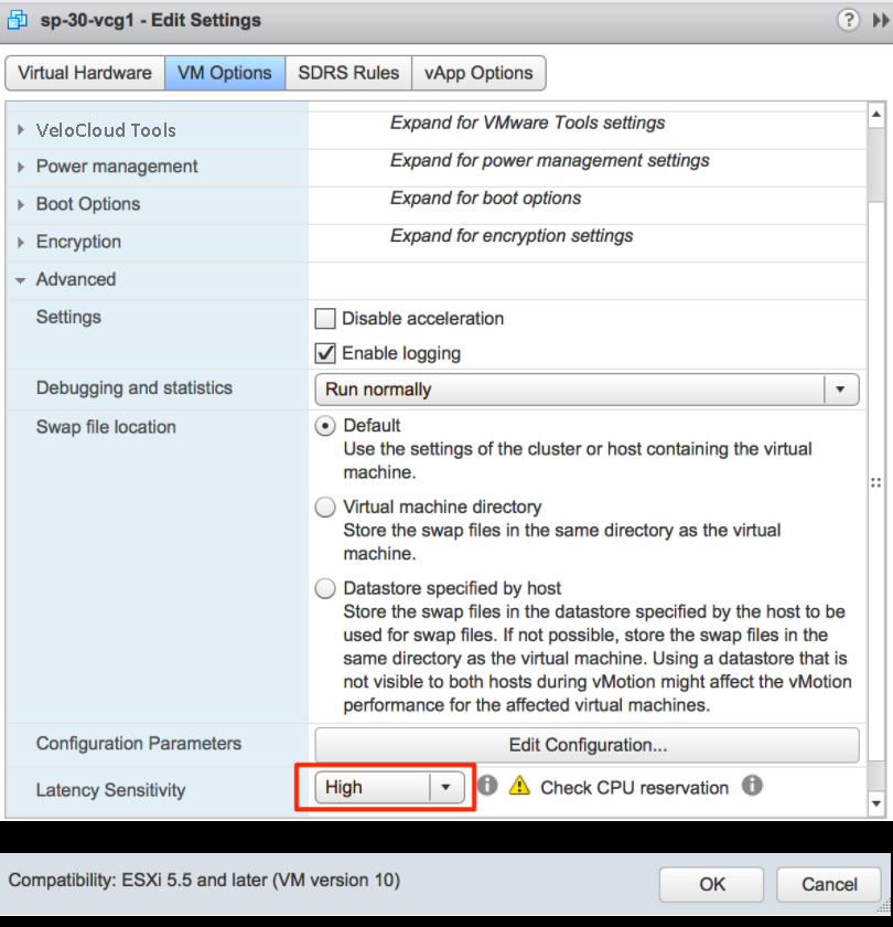
Set the Latency Sensitivity to 'High'.
Procedure to adjust Latency Sensitivity:
Browse to the virtual machine in the vSphere Client.
To find a virtual machine, select a data center, folder, cluster, resource pool, or host.
Select the VMs tab.
Right-click the virtual machine, and then select Edit Settings.
Select VM Options, and then select Advanced.
Select High from the Latency Sensitivity drop-down menu.
Select OK.
Set the CPU reservation to 100%.
Set the CPU shares to high.
Set the CPU Limit to Unlimited.
8 vCPUs (The system supports 4 vCPUs but yields lower performance levels.)
Important: Map all the vCPU cores to the same socket, with the Cores per Socket parameter set to either 8 (8 vCPUs) or 4 (4 vCPUs).
Note: To achieve maximum performance, deactivate hyper-threading.
Procedure to allocate CPU resources:
Select Virtual Machines in the Arista Host Client inventory.
Right-click a virtual machine from the list, and then select Edit settings from the pop-up menu.
On the Virtual Hardware tab, expand CPU, and then allocate CPU capacity for the virtual machine.
Table 5. Virtual Hardware - Options and Descriptions
Option
Description
Reservation
Guaranteed CPU allocation for this virtual machine.
Limit
Upper limit for this virtual machine’s CPU allocation. Select Unlimited to specify no upper limit.
Shares
CPU shares for this virtual machine in relation to the parent’s total. Sibling virtual machines share resources according to their relative share values bounded by the reservation and limit. Select Low, Normal, or High, which specify share values respectively in a 1:2:4 ratio. Select Custom to give each virtual machine a specific number of shares, which expresses a proportional weight.
To activate CPU affinity, perform the following steps:
In the vSphere Web Client, go to the VM Settings tab.
Choose the Options tab, and then select Advanced General > Configuration Parameters.
Add entries for numa.nodeAffinity=0, 1, ..., where 0 and 1 are the processor socket numbers.
vNIC must be of type 'vmxnet3' (or SR-IOV, see SR-IOV section for support details).
Minimum of any one of the following vNICs:
The First vNIC is the public (outside) interface, which must be an untagged interface.
The Second vNIC is optional and acts as the private (inside) interface that can support VLAN tagging dot1q and Q-in-Q. This interface typically faces the PE router or L3 switch.
Optional vNIC (if a separate management/OAM interface is required).
Memory reservation is set to ‘maximum.’
16GB of memory (32GB RAM when enabling certificate-based authentication).
64 GB of virtual disk (96GB disk when enabling certificate- based authentication).
Note: Arista uses the above defined settings to obtain scale and performance numbers. Settings deviating from the specified requirements remain untested and often yield unpredictable performance and scale results.
If using KVM:
vNIC must be of 'Linux Bridge' type. (SR-IOV is required for high performance, see SR-IOV section for support details).
8 vCPUs (The system supports 4 vCPUs but yields lower performance levels).
Important: Map all the vCPU cores to the same socket, with the Cores per Socket parameter set to either 8 (8 vCPUs) or 4 (4 vCPUs).
Note: To achieve maximum performance, deactivate hyper-threading.
16GB of memory (32GB RAM when enabling certificate- based authentication)
Minimum of any one of the following vNICs:
The First vNIC is the public (outside) interface, which must be an untagged interface.
The Second vNIC is optional and acts as the private (inside) interface that can support VLAN tagging dot1q and Q-in-Q. This interface typically faces the PE router or L3 switch.
Optional vNIC (if a separate management/OAM interface is required).
64 GB of virtual disk (96GB disk when enabling certificate- based authentication).
Firewall/NAT Requirements
Note: A firewall or NAT device situated in front of the Gateway triggers these specific configuration requirements.
The firewall must allow outbound traffic from the Gateway to TCP port 443 (for communication with Orchestrator).
The firewall must allow inbound traffic from the Internet to UDP/2426 (VCMP), UDP/4500, and UDP/500. The firewall must allow IP/50 (ESP) whenever the deployment excludes NAT.
The NAT device translates these ports to an externally reachable IP address. The configuration supports both the 1:1 NAT and port translations.
Use of DPDK on Gateways
To improve packet throughput performance, Gateways take advantage of Data Plane Development Kit (DPDK) technology. Intel’s DPDK provides data-plane libraries and drivers that offload TCP packet processing from the OS kernel to user-space processes, thereby increasing packet throughput. For additional details, see https://www.dpdk.org/.
VeloCloud-hosted Gateways and Partner Gateways use DPDK on data-plane interfaces while reserving standard kernel processing for management-plane traffic. On a typical VeloCloud-hosted Gateway, eth0 handles management-plane traffic without DPDK, while eth1, eth2, and eth3 manage data-plane traffic via DPDK.
Gateway Installation Procedures
This section discusses the Gateway installation procedures.
In general, installing the Gateway involves the following steps:
Create Gateway on the Orchestrator and make a note of the activation key.
Configure Gateway on the Orchestrator.
Create the cloud-init file.
Create the VM in ESXi or KVM.
Boot the Gateway VM and ensure the Gateway cloud-init initializes properly. At this stage, the Gateway should already activate itself against the Orchestrator.
Verify connectivity and deactivate cloud-init.
Important: Gateway supports both the virtual switch and SR-IOV. This guide specifies the SR-IOV as an optional configuration step.
Pre-Installation Considerations
The Partner Gateway provides different configuration options. Gateway installation requires preparing a configuration worksheet.
Table 6. Configuration Worksheet
Gateway
Version
OVA/QCOW2 file location
Activation Key
Orchestrator (IP ADDRESS/vco-fqdn-hostname)
Hostname
Hypervisor
Address/Cluster name
Storage
Root volume datastore (>40GB recommended)
CPU Allocation
CPU Allocation for KVM/ESXi.
Installation Selections
DPDK - This is optional and the system enables it by default for higher throughput. To deactivate DPDK, contact https://www.arista.com/en/support.
Version- Should be same or lower than the Orchestrator
OVA/QCOW2 file location- Plan the file location and disk allocation
Activation Key
Orchestrator (IP ADDRESS/vco-fqdn-hostname)
Hostname - Valid Linux Hostname “RFC 1123”
Create a Gateway and Get the Activation Key
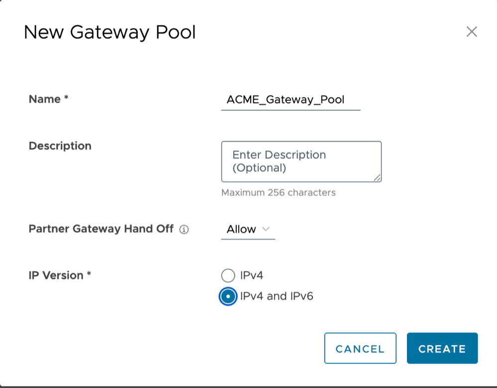
Go to Operator > Gateway Management > Gateway Pools.
Click New Gateway Pool.
Figure 1. New Gateway Pool
Enter a name and description for the new Gateway Pool.
Select Allow from the Partner Gateway Handoff drop-down menu to enable the option to include the Partner Gateway in this Gateway pool.
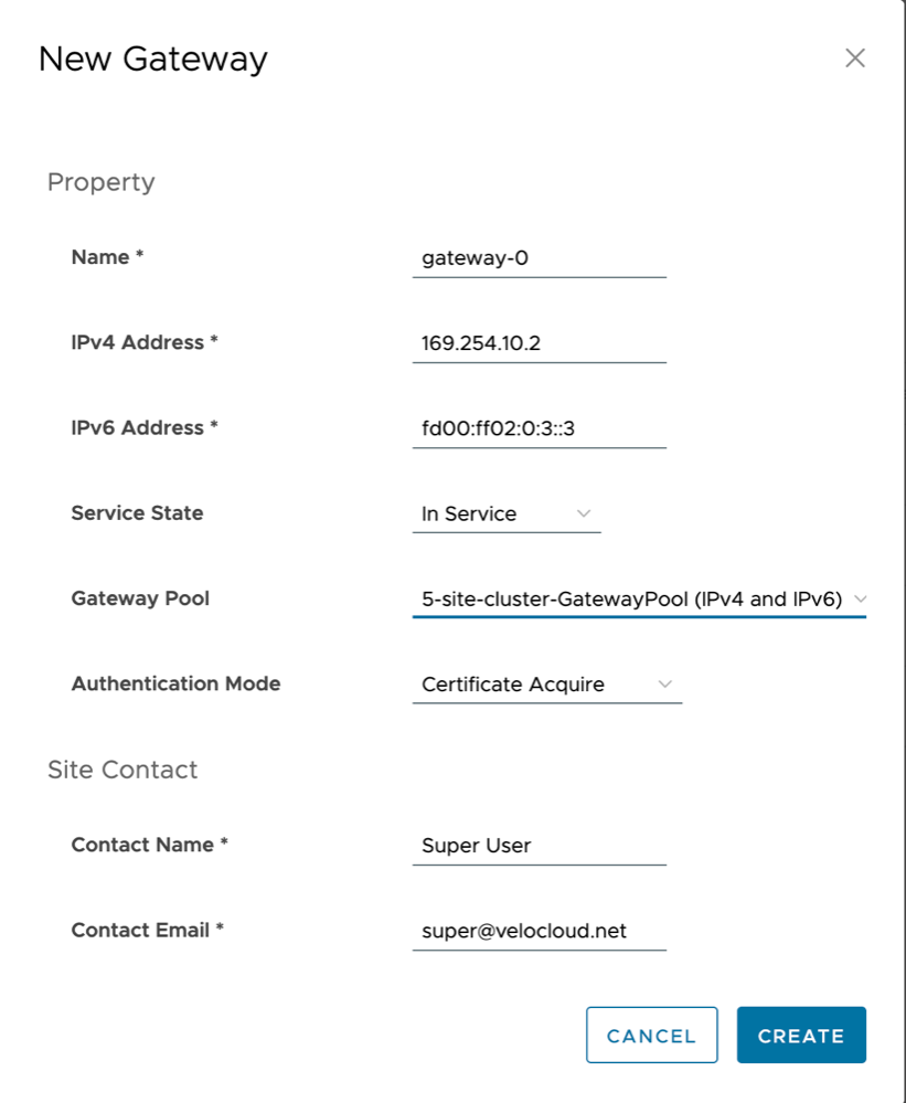
Go to Operator > Gateway Management > Gateway and create a new Gateway. Assign it to the pool. The entered IP address of the Gateway must match the public IP address of the Gateway. To verify, run curl ipinfo.io/ip on the Gateway to return the Gateway's public IP.
Figure 2. New Gateway
Note the activation key and add it to the worksheet.
Enable Partner Gateway Mode
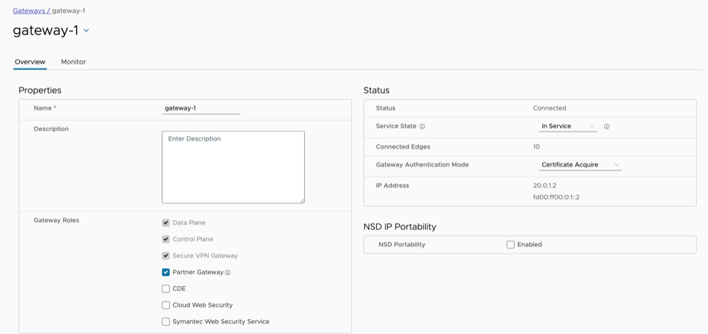
Go to Operator > Gateway Management > Gateways and select the Gateway.
Figure 3. Partner Gateway
Select the Partner Gateway checkbox to enable the Partner Gateway.
The system supports several additional configuration parameters. The most common are the following:
Advertise 0.0.0.0/0 with no encrypt – This option will enable the Partner Gateway to advertise a path to Cloud traffic for the SAAS Application. The business policy configuration determines whether the customer utilizes this path when the Encrypt Flag remains off.
Advertise the Orchestrator IP as a /32 with encrypt.
This will force the traffic that is sent from the Edge to the Orchestrator to take the Gateway Path. This approach ensures predictable behavior as the Edge reaches the Orchestrator.
Networking
Important: The following procedure and screenshots focus on the most common deployment: the 2-ARM Gateway installation. The section OAM Interface and Static Routes details the addition of an OAM network.
Figure 4. Partner Gateway Deployment
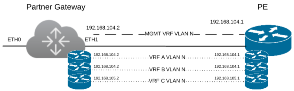
The diagram above is a representation of the Gateway in a 2-ARM deployment. In this example, assume eth0 is the interface facing the public network (Internet) and eth1 is the interface facing the internal network (handoff or VRF interface).
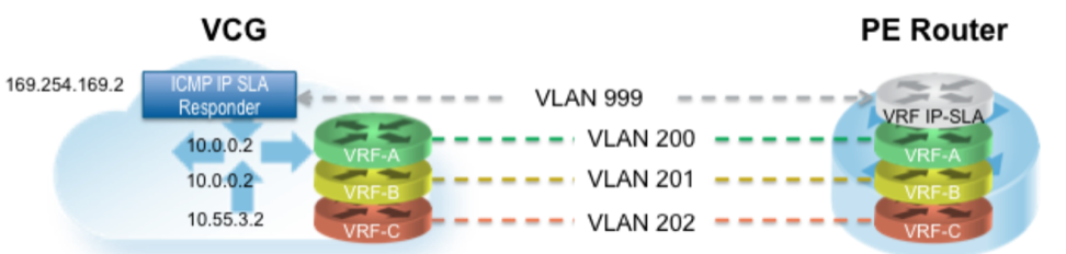
Note: The Management VRF verifies handoff interface connectivity and accelerates failover time by sending periodic ARP refreshes to the default Gateway IP. Best practices suggest a dedicated VRF on the PE router for this specific purpose. Optionally, the PE router can use VRF to send an IP SLA probe to the Gateway to check its status (the Gateway has a stateful ICMP responder that responds to ping only when its service is up). The absence of a dedicated Management VRF allows the use of a customer VRF for management tasks, though this practice remains non-recommended.
The Internet-facing network requires only a basic network configuration.
Table 8. Internet Facing Network
ETH0 – Internet Facing Network
IPv4_Address
IPv4_Netmask
IPv4_Default_gateway
DNS_Server_Primary
DNS_Server_Secondary
Configuration of the handoff interface requires both the selection of a handoff type and the specific settings for the Management VRF.
To access the Gateway, create a console password or an SSH public key.
Cloud-Init Creation
The cloud-init configuration uses the Gateway configuration options defined in the worksheet. The cloud-init configuration consists of two main configuration files: the meta-data file and the user-data file. The meta-data file contains the Gateway's network configuration, and the user-data contains the Gateway Software configuration. This file identifies the specific Gateway instance during installation.
Below are the templates for both meta_data and user_data files. Omitting the network-config file triggers the default DHCP configuration.
Fill the templates with the information in the worksheet. All #_VARIABLE_# must be replaced, and check any #ACTION#
Important: The template assumes users are using a static configuration for the interfaces. It also assumes that users either use SR-IOV for all interfaces or none at all.
network-config file (leading spaces are important!)
Note: The network-config examples below describe configuring the virtual machine with two network interfaces, eth0 and eth1, with static IP addresses. eth0 is the primary interface with a default route and a metric of 1. eth1 is the secondary interface with a default route and a metric of 13. The system utilizes password authentication for the default (vcadmin) account. In addition, the system adds the SSH authorized key for the vcadmin user. The SD-WAN Gateway automatically activates to the SD-WAN Orchestrator with the provided activation_code.
The default username for the password configured in the user-data file is 'vcadmin'. Use this default username to login to the Gateway for the first time.
Important: Always validate user-data and meta-data, using http://www.yamllint.com/ network-config should also be a valid network configuration ( https://docs.cloud-init.io/en/latest/reference/network-config.html (version 25.1.4)) . The Windows and Mac copy-paste features sometimes introduce Smart Quotes, which corrupt files. Executing the command below verifies that the file contains no smart quotes.
sed s/[”“]/'"'/g /tmp/user-data > /tmp/user-data_new
Create ISO File
Finalizing the configuration requires packaging the files into an ISO image. The virtual machine utilizes this ISO image as a virtual configuration CD. The following Linux command generates the ISO image titled vcg01-cidata.iso:
This procedure requires a specific NIC card. Arista certifies the following chip sets to work with the Gateway.
Intel 82599/82599ES
Intel X710/XL710
Note: Before using the Intel X710/XL710 cards in SR-IOV mode, install the supported Firmware and Driver versions.
Enabling SR-IOV on ESXi is an optional configuration. To enable SR-IOV on ESXi:
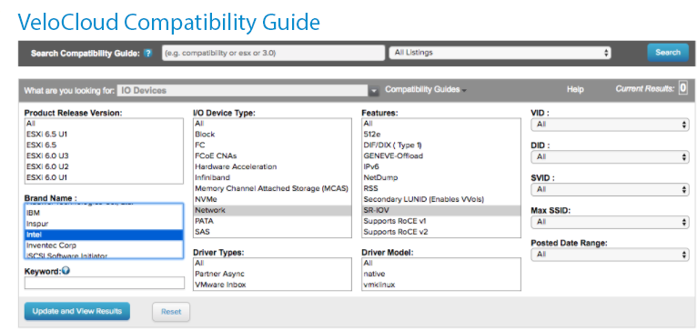
Ensure the NIC supports SR-IOV. Check the Hardware Compatibility List (HCL) at Arista Documentation.
Brand Name: Intel
I/O Device Type: Network
Features: SR-IOV
Figure 5. Compatibility Guide
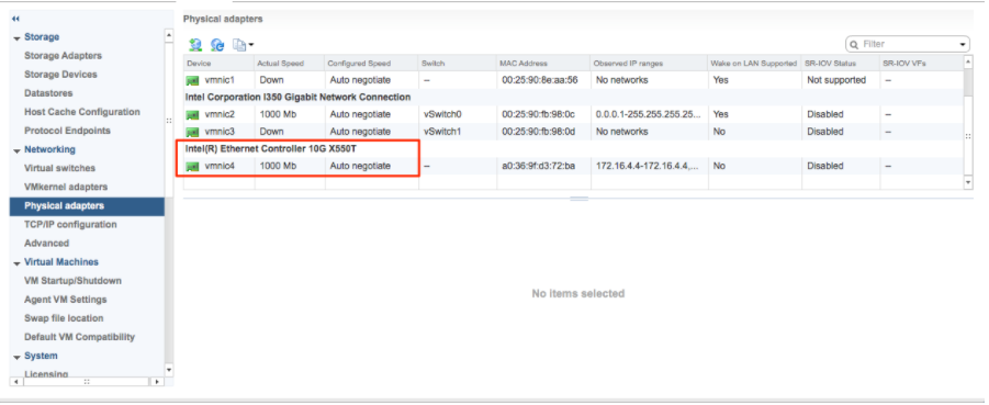
Go to the specific Arista host, select the Configure tab, then choose Physical adapters.
Figure 6. Physical Adapters
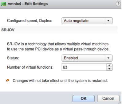
Select Edit Settings. Change Status to Enabled and specify the number of required virtual functions. This number varies by the type of NIC card.
Reboot the hypervisor.
Figure 7. Reboot the hypervisor
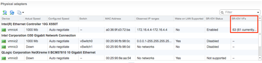
A successful SR-IOV enablement displays the number of Virtual Functions (VFs) under the specified NIC, following an ESXi reboot.
Figure 8. Virtual Functions List
Note: To support VLAN tagging on SR-IOV interfaces, user must configure VLAN ID 4095 (Allow All) on the Port Group connected to the SR-IOV interface. For additional information, see VLAN Configuration.
Install Gateway on ESXi
This topic describes the procedure for installing the Gateway OVA on ESXi.
Note: ESXi versions 6.7, 6.7U3, 7.0, 7.0U3, and 8.0.1 support this specific deployment model.
Important: Completion of the OVA installation requires mounting the cloud-init ISO file as a CD-ROM before the Gateway VM powers on. Failure to do so requires redeploying the VM.
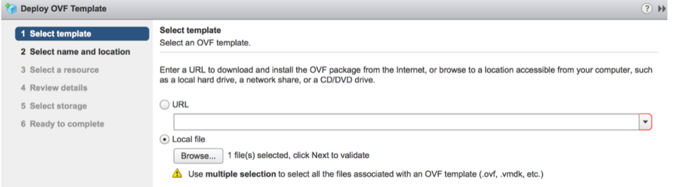
Select the ESXi host, go to Actions, and then select Deploy OVF Template. Select the Gateway OVA file provided by Arista, then select Next.
Figure 9. Deploying OVF Template
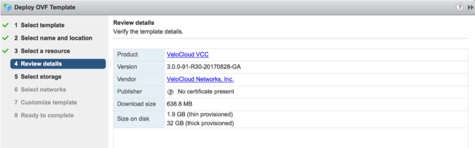
Review the template details in Step 4 (Review details) of the Deploy OVA/OVF Template wizard as shown in the image.
Figure 10. Review details
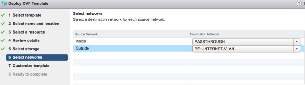
For the Select networks step, the OVA comes with two pre-defined networks (vNICs).
Table 11. Pre-defined Networks
vNIC
Description
Inside
This vNIC faces the PE router and handles traffic handoff to the MPLS PE or L3 switch. This vNIC typically binds to a port group configured for VLAN pass-through (VLAN 4095).
Outside
This is the vNIC facing the Internet. This vNIC requires non-tagged L2 frames and typically binds to a port group distinct from the Inside vNIC.
Figure 11. Select Networks
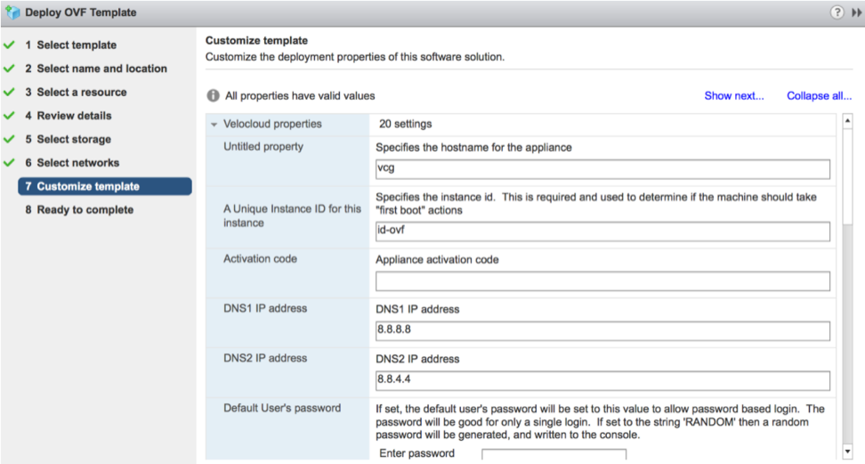
For the Customize template step, do not change anything. Use vApp to configure the VM. This example excludes the use of vApp. Select Next to continue with deploying the OVA.
Figure 12. Customize Template
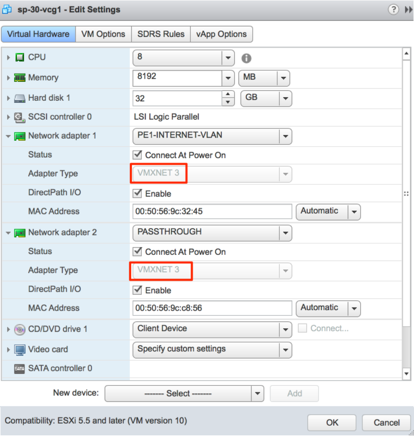
After the successful deployment of the VM, return to the VM and select Edit Settings.
The system creates two vNICs with adapter type = vmxnet3.
Figure 13. Edit Settings
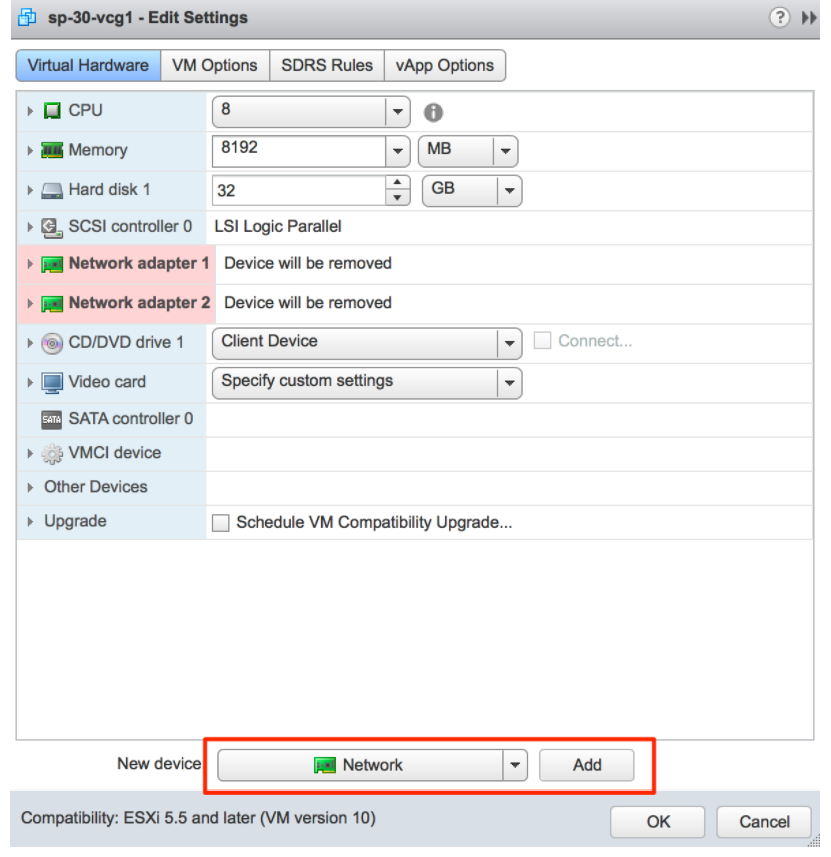
(Optional for SR-IOV) Perform this step only when using SR-IOV. Remove the two default vmxnet3 vNICs, then add SR-IOV interfaces.
Figure 14. Remove default vmxnet3 vNICs
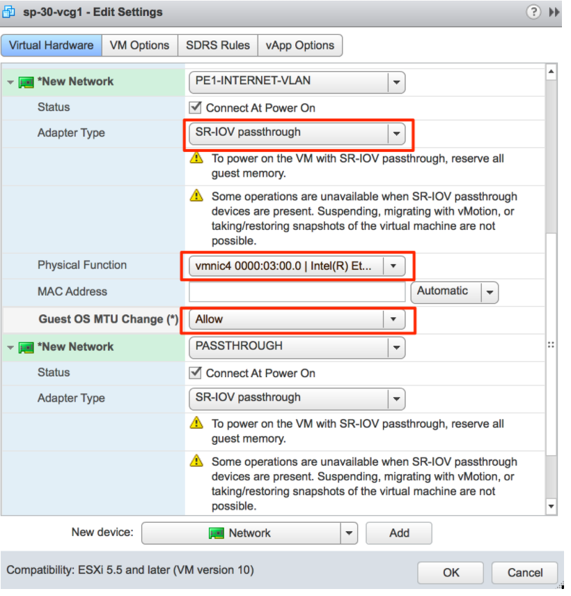
When adding the two new SR-IOV vNICs, use the same port group as the original two vmxnet3 vNICs. Make sure the Adapter Type is SR-IOV passthrough. Select the correct physical port to use and set the Guest OS MTU Change to Allow. After adding the two vNICs, select OK.
Figure 15. Add SR-IOV vNICs
As Gateway is a real-time application, configure the Latency Sensitivity to High.
Figure 16. Latency Sensitivity
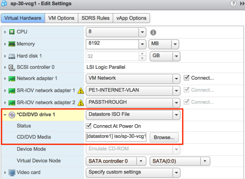
Refer to Cloud-init Creation. Packaging the cloud-init data into an ISO file facilitates its use as a virtual CD-ROM. Mount this file as a CD-ROM.
Note: Upload this file to the datastore.
Figure 17. CD/DVD Drive 1
Start the VM.
Activate SR-IOV on KVM
To activate the SR-IOV mode on KVM, perform the following steps.
This procedure requires a specific NIC card. The Gateway and Edge support the following certified chipsets.
Intel 82599/82599ES
Intel X710/XL710
Note: Before using Intel X710/XL710 cards in SR-IOV mode on KVM, install the supported Firmware and Driver versions correctly.
Note: Deploying the KVM Virtual Edge in a High-Availability topology turns off SR-IOV support. For High-Availability deployments, do not activate SR-IOV for that KVM Edge pair.
To activate SR-IOV on KVM:
Activate SR-IOV in the BIOS, depending on your BIOS. Log in to the BIOS console and look for SR-IOV Support/DMA. Verify support on the prompt by checking that Intel has the correct CPU flag.
cat /proc/cpuinfo | grep vmx
Add the options on boot (in /etc/default/grub).
GRUB_CMDLINE_LINUX="intel_iommu=on"
Run the following commands: update-grub and update-initramfs-u.
Run the update-initramfs-u command and reboot the Server.
Use the modinfo command to verify if the installation is successful.
velocloud@KVMperf1:~$ modinfo ixgbe and ip link
filename: /lib/modules/4.4.0-62-generic/updates/drivers/net/ethernet/intel/ixgbe/ixgbe.ko
version: 5.0.4
license: GPL
description: Intel(R) 10GbE PCI Express Linux Network Driver
author: Intel Corporation, <This email address is being protected from spambots. You need JavaScript enabled to view it.>
srcversion: BA7E024DFE57A92C4F1DC93
For Intel X710/XL710 cards in SR-IOV mode:
Download and install the i40e driver from the Intel website.
This topic discusses how to install the Gateway qcow on KVM.
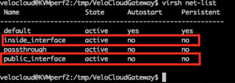
KVM provides multiple ways to provide networking to virtual machines. Configuring the VM requires prior provisioning of the libvirt networking. There are multiple ways to configure networking in KVM. For a full configuration of options on how to configure Networks on libvirt, see the following link:
<network >
<name > inside_interface < /name > <!--This is the network name-->
<model type = 'virtio'/>
<forward mode = "bridge"/>
<bridge name = "insideinterface"/>
<virtualport type = 'openvswitch' > </virtualport >
<vlan trunk = 'yes' > </vlan >
<tag id = '200'/> < !—Define all the VLANS for this Bridge - ->
<tag id = '201'/> < !—Define all the VLANS for this Bridge - ->
<tag id = '202'/> < !—Define all the VLANS for this Bridge - ->
</network >
OpenVSwitch mode requires creating and activating the basic networks before the VM launch.
Note: SR-IOV mode bypasses this validation step because network creation occurs only after the VM launch.
Figure 18. OpenVSwitch Mode
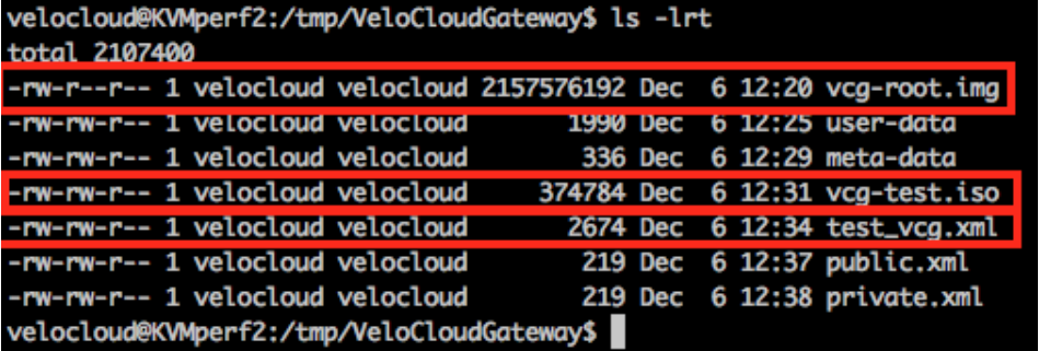
Edit the VM XML file. There are multiple ways to create a Virtual Machine in KVM. Define the VM in an XML file and create it using libvirt, using the sample VM XML template specific to OpenVSwitch mode and SR-IOV mode.
vi my_vm.xml
The following is a sample template of a VM which uses OpenVSwitch interfaces. Use this template by making edits wherever applicable.
When using SR-IOV mode, after launching the VM, set the following on the Virtual Functions (VFs) used:
Set the spoofcheck off.
ip link set eth1 vf 0 spoofchk off
Set the Trusted mode on.
ip link set dev eth1 vf 0 trust on
Set the VLAN, if required.
ip link set eth1 vf 0 vlan 3500
Note: OpenVSwitch (OVS) mode excludes the Virtual Functions configuration step.
Console into the VM.
virsh list
Id Name State
----------------------------------------------------
25 test_vcg running
velocloud@KVMperf2$ virsh console 25
Connected to domain test_vcg
Escape character is ^]
Special Considerations for KVM Host:
Deactivate GRO (Generic Receive Offload) on physical interfaces (to avoid unnecessary re-fragmentation in the Gateway).
ethtool –K <interface> gro off tx off
Deactivate CPU C-states (power states affect real-time performance). Typically, perform this step as part of kernel boot options by appending processor.max_cstate=1 or deactivate in the BIOS.
Production deployments require pinning vCPUs to the instance. Production standards prohibit the over-subscription of cores.
Post-Installation Tasks
This section describes post-installation and installation verification steps.
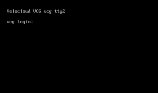
A successful installation enables immediate login access to the VM.
A successful configuration triggers the login prompt on the console. The console displays the prompt name as defined in the cloud-init configuration.
Figure 20. Login Prompt
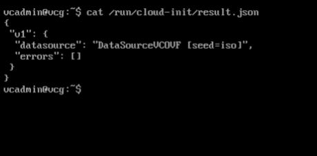
Refer to /run/cloud-init/result.json.
The following output signals a successful cloud-init run.
Figure 21. Successful cloud-init run
Before proceeding, confirm the Gateway's registration with the Orchestrator.
Figure 22. Registered Gateway
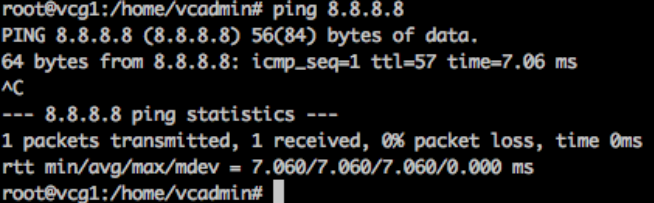
Verify Outside Connectivity.
Figure 23. Verify Connectivity
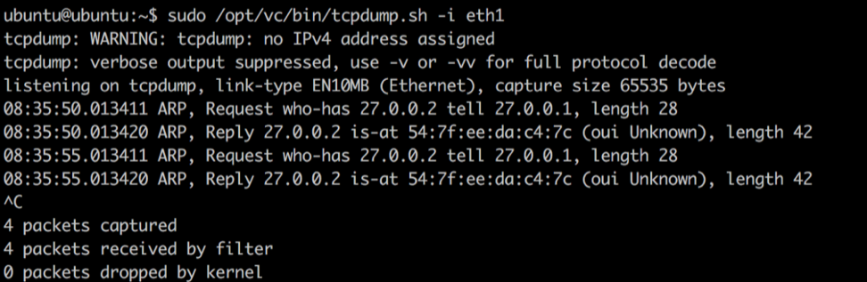
Verify that the MGMT VRF is responding to ARPs.
Figure 24. MGMT VRF
Deactivate cloud-init so it does not run on every boot.
Note: Upgrade to versions 6.1.x or 6.4.x or 7.0.x requires deactivating cloud-init for any OVA deployed on vSphere or QCOW deployed on KVM. This ensures that the upgrade does not erase customization settings, such as network configurations or passwords. The main change in behavior is due to the upgraded cloud-init version in the mentioned releases.
touch /etc/cloud/cloud-init.disabled
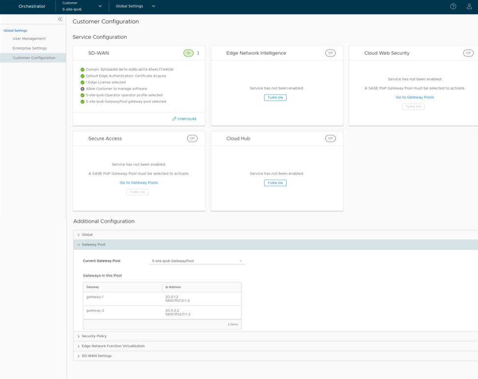
Associate the new Gateway pool with the Customer.
Figure 25. Customer Configuration
Associate the Gateway with an Edge. For additional information, see the Assign Partner Gateway Handoff section in the Arista VeloCloud SD-WAN Administration Guide.
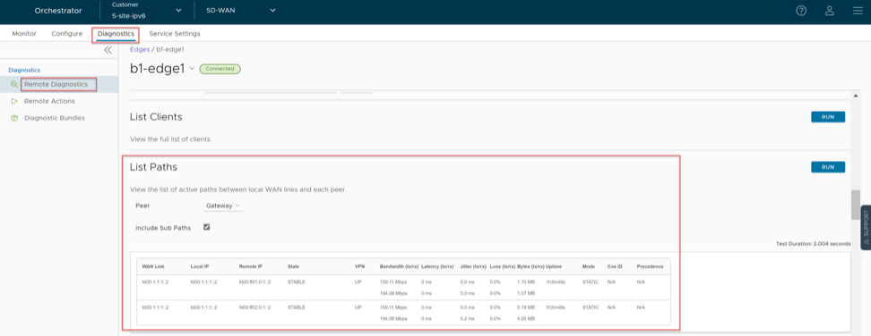
Verify that the Edge is able to establish a tunnel with the Gateway on the Internet side. From the Orchestrator, go to Monitor > Edges > [Edge] > Overview. From the Orchestrator, go to Diagnostics > Remote Diagnostics > [Edge] > List Paths, and then select Run to view the list of active paths.
Figure 26. List Paths
Configure the Handoff interface.
Verify whether the BGP session is up.
Change the network configuration. Network configuration files reside under /etc/netplan.
Example network configuration (white space is important!) - /etc/netplan/50-cloud-init.yaml:
Important: Enabling cloud-init triggers a network configuration regeneration on every boot. To make changes to the location configuration, deactivate cloud-init or deactivate the cloud-init network configuration component:
In the figure below (VRF/VLAN Hand Off to PE), assume eth0 is the interface facing the public network (Internet), and eth1 is the interface facing the internal network (customer VRF via the PE). The Orchestrator manages BGP peering configuration for each customer and VRF under Configure > Customer.
Note: Configuring the IP address for each VRF occurs at the customer level.
The management VRF inherits its IP address directly from the SD-WAN Gateway interface configuration in Linux.
Figure 27. VRF/VLAN Hand Off
The SD-WAN Gateway creates a management VRF to send periodic ARP refreshes to the default gateway IP address to determine the next-hop MAC address. Arista recommends setting up a dedicated VRF on the PE router for this purpose. The PE router can also use the same management VRF to send an IP SLA probe to the SD-WAN Gateway to check for SD-WAN Gateway status (SD-WAN Gateway has a stateful ICMP responder that responds to ping only when its service is up). The Management VRF operates without requiring BGP peering. One of the customer VRFs can function as a Management VRF in the absence of a dedicated management setup, though this practice remains non-recommended.
Edit the /etc/config/gatewayd and specify the correct VCMP and WAN interface. VCMP interface is the public interface that terminates the overlay tunnels. The WAN interface in this context is the handoff interface facing the PE.
Configure the Management VRF. SD-WAN Gateway uses this VRF to ARP for next-hop MAC (PE router). All VRFs on the SD-WAN Gateway share the same next-hop MAC address. Configure the Management VRF parameter in /etc/config/gatewayd.
The Management VRF is the same VRF used by the PE router to send the IP SLA probe to. The SD-WAN Gateway responds to the ICMP probe only when the service remains active, and Edges maintain an established connection. The table below defines each required parameter. This example uses Management VRF on the 802.1q VLAN ID of 1000.
Edit the /etc/config/gatewayd-tunnel to include both interfaces in the wan parameter. Save the change. wan="eth0 eth1"
Remove Blocked Subnets
By default, the SD-WAN Gateway blocks traffic to 10.0.0.0/8 and 172.16.0.0/14. Removing these entries ensures the SD-WAN Gateway properly directs traffic to private subnets. Retaining the default file configuration results in the following messages in /var/log/gwd.log when the system attempts to route traffic to blocked subnets:
2015-12-18T12:49:55.639  ERR     [NET] proto_ip_recv_handler:494 Dropping packet destined for
10.10.150.254, which is a blocked subnet.
2015-12-18T12:52:27.764  ERR     [NET] proto_ip_recv_handler:494 Dropping packet destined for
10.10.150.254, which is a blocked subnet. [message repeated 48 times]
2015-12-18T12:52:27.764  ERR     [NET] proto_ip_recv_handler:494 Dropping packet destined for
10.10.150.10, which is a blocked subnet.
On the SD-WAN Gateway, edit /opt/vc/etc/vc_blocked_subnets.jsonfile.
Remove the two networks. The following example illustrates the file's final state after modification.
[]
Save the change.
Restart the SD-WAN Gateway process by sudo /opt/vc/bin/vc_procmon restart.
Upgrade Gateway
This section discusses how to upgrade a Gateway installation.
Important: This procedure does not work with upgrading a Gateway image version from 3.x to 4.x due to a significant platform changes. Upgrading from a 3.x to 4.x image requires a new Gateway deployment and reactivation. Please refer to the Partner Gateway Upgrade and Migration 3.4 to 4.0 section for upgrade information.
Note: Currently, Arista does not support downgrading for the Edge Cloud Orchestrator and VeloCloud Gateway. So before upgrading the Orchestrator or Gateway, Arista recommends you to back up the system prior to upgrade for easy recovery in the event the upgrade is not successfully completed.
Authenticate Software Update Package Via Digital Signature
The software installer in the Orchestrator version 4.3.0 and higher now has the ability to authenticate the software update package using a digital signature.
Prior to upgrading to a newer version of the software, make sure the public key exists to verify the package. The known public key location to verify signature has the following format, /var/lib/velocloud/software_update/keys/software.key. Alternatively, the key can be provided on the command line using --pubkey- parameter.
The current release public key has the following format:
-----BEGIN PUBLIC KEY-----
MHYwEAYHKoZIzj0CAQYFK4EEACIDYgAEbjZ08w3RNJvuOICBp8fysU/3opLejsrP
pArA1IyKeUzU0U31MU4kPcLdggojobNfs3i1kvyvGvprEmfGYWzc3dXUyT9Tv73C
lVgYPLNd/nOxJsXomROKogfvJdYFuy4/
-----END PUBLIC KEY----
If the key is missing or the signature cannot be verified, The Edge notifiies the Operator that the package is untrusted with an option to proceed or not proceed.
To skip verification, use --untrusted parameter.
If running in batch mode or not on the terminal, the installation aborts unless you specify the "--untrusted" option on the command line.
By default, the installer runs in interactive mode and may issue prompts. For automated scripts, use --batch parameter to suppress prompts.
Upgrade Procedures
To upgrade a Gateway installation:
Download the Gateway update package.
Upload the image to the Gateway system using, for example, the scp command). Copy the image to the following location on the system: /var/lib/velocloud/software_update/vcg_update.tar
Connect to the Gateway console and run:
sudo /opt/vc/bin/vcg_software_update
Activate Replacement Partner Gateway
This section discusses activating a replacement Partner Gateway.
Overview
Gateway activation keys do not have the same default 30 day lifetime as Edges. In fact, a Gateway activation key has an infinite lifespan. If an on-premises Gateway fails and you want to replace it with a new Gateway using the same name and IP address, you can use the same activation key used for the original Gateway.
As a result, for most Gateway issues, creating a new VM provides the quickest method of recovery and register it with the Orchestrator using the failed Gateway activation key. This saves you a lot of time as Orchestrator pushes the existing configuration to this new instance. Most Partners prefer this approach over configuring a new Gateway from scratch.
Prerequisites
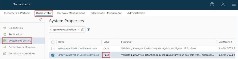
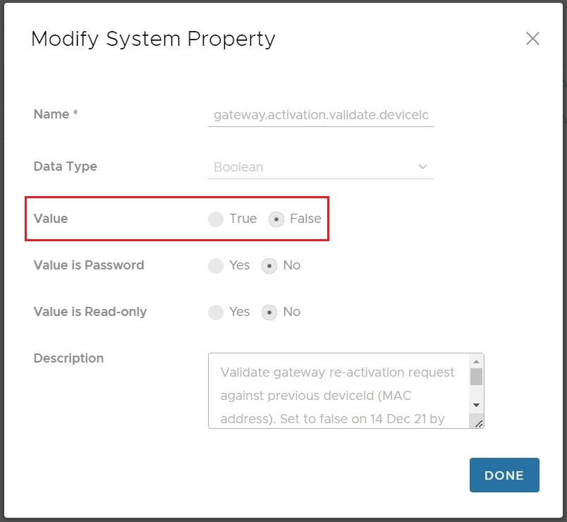
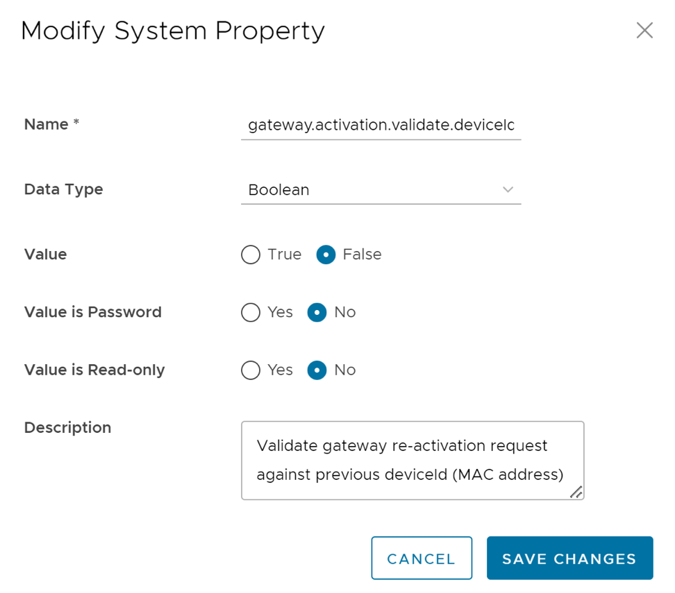
Before you can use this Gateway replacement method, you must adjust the System Property gateway.activation.validate.deviceID and set the value to false. To do this you or another Operator with a Superuser role must go to Orchestrator > System Properties and search for gateway.activation and inspect gateway.activation.validate.deviceID. If the Value is already false, then you are ready for the next steps. If the Value is true, then a Gateway reactivation does not work, and you need to modify this System Property by selecting it.
Figure 28. System Properties
Figure 29. Modify System Property
You must be an Operator with a Superuser role to make this change. By default, the Orchestrator performs a deviceID verification, and with this System Property set to true, activating a replacement Gateway fails because the deviceID is not the same as the original Gateway. Setting this property to false disables the verification process on the Orchestrator.
Note: There are no adverse effects to changing this value. You may leave it as false since the Gateway authentication keys have an indefinite validation.
Replacement Partner Gateway Workflow
Follow these steps to activate a replacement Partner Gateway:
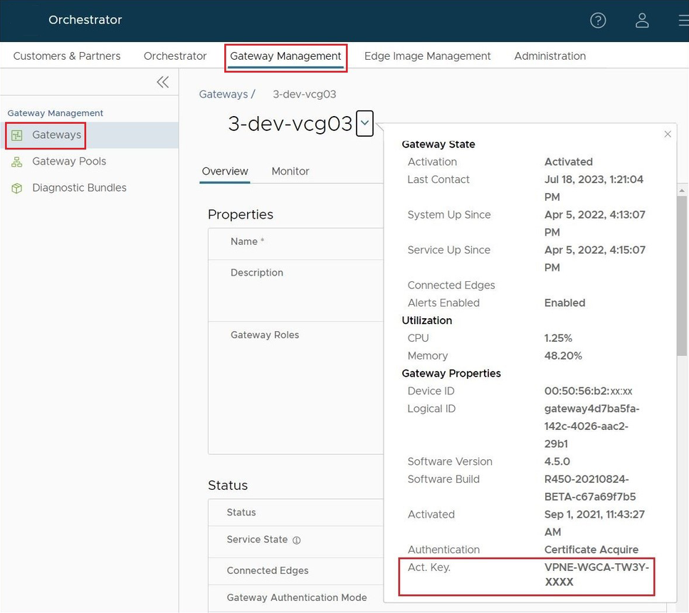
Locate the original activation key by navigating to Gateway Management > Gateways and selecting the name of the Gateway you are replacing. Select the down arrow beside the name and note the activation key.
Figure 30. Gateway Management
Use the activation key to activate the replacement Gateway on your newly spun up VM: /opt/vc/bin/activate.py-s vco_name_or_ip
activation_key.
Edit the /etc/ntpd.conf file to change the NTP configuration.
OAM Interface and Static Routes
If deploying Gateways with an OAM interface, complete the following steps.
Add an additional interface to the VM (ETH2).
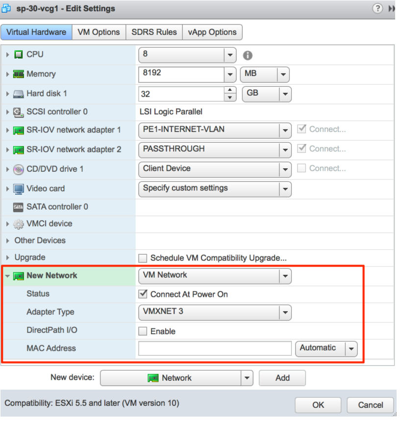
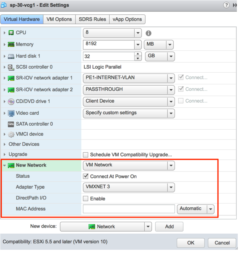
Arista - If configuring a dedicated VNIC for Management/OAM, add another vNIC of the type vmxnet3. Select Edit Settings to copy the vNIC MAC address.
Figure 31. Edit OAM Interface SettingsKVM - If configuring a dedicated VNIC for Management/OAM, make sure you have a libvirt network called oam-network. Then add the following lines to your XML VM structure:
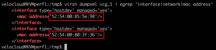
In some installations, a configuration provides the capability to mix and match and provide different interface types for the Gateway. This generally happens if you have an OAM without SR-IOV. This custom configuration requires additional steps since this causes the interfaces to become active out of order.
Record the MAC address of each interface.
Arista - After creating the VM, go to Edit Settings and copy the Mac address.
Figure 32. Edit SR-IOV Settings
KVM - After defining the VM, run the following command:
Figure 33. KVM Commands
Special Consideration When Using 802.1ad Encapsulation
In some instances, the 802.1ad devices do not populate the outer tag EtherType with 0x88A8. It requires a special change for user data to interoperate with these devices.
Assuming a Management VRF has a configuration with the S-Tag, 20, and the C-Tag, 100, edit the vrf_vlan section in / etc/ config/ gatewayd. Also, define resp_mode to 1 and allow the Gateway to relax its check to allow Ethernet frames with the incorrect EtherType of 0x8100 in the outer header.
SNMP Integration
This section discusses configuring SNMP integration.
For additional information on SNMP configuration, see https://www.net-snmp.org/docs/man/ documentation. To configure SNMP integration, use the following steps:
Edit /etc/snmp/snmpd.conf.
Add the following lines to the config file with the source IP address of the systems connecting to SNMP service. You can configure using either SNMPv2c or SNMPv3.
The following example configures access to all counters from the localhost using the community string vc-vcg and from 10.0.0.0/8 with the community string myentprisecommunity using SNMPv2c version.
agentAddress udp:161
# com2sec sec.name source community
com2sec local localhost vc-vcg
com2sec myenterprise 10.0.0.0/8 myentprisecommunity# group access.name sec.model sec.name
group rogroup v2c local
group rogroup v2c myenterpriseview all included .1 80
# access access.name context sec.model sec.level match read write notif
access rogroup "" any noauth exact all none none#sysLocation Sitting on the Dock of the Bay
#sysContact Me <This email address is being protected from spambots. You need JavaScript enabled to view it.>sysServices 72master agentx#
# Process Monitoring
## At least one 'gwd' process
proc gwd
# At least one 'mgd' process
proc mgd#
# Disk Monitoring
#
# 100MBs required on root disk, 5% free on /var, 10% free on all other disks
disk / 100000
disk /var 5%
includeAllDisks 10%#
# System Load
#
# Unacceptable 1-, 5-, and 15-minute load averages
load 12 10 5
Note: In the above example, the process gwd includes the entire Data and Control Plane of the Gateway. The Management Plane Daemon (mgd) has the responsiblity for communication with the Orchestrator. This process keeps it isolated from gwd so that in the incident of a total failure of the gwd process, the Orchestrator accept configuration changes or software updates required to resolve the failure.
The following example shows a configuration using SNMPv3 version.
vcadmin: ~$ cat / etc/snmp/snmpd.conf
###############################################################################
#
# EXAMPLE.conf:
# An example configuration file for configuring the Net-SNMP agent ('snmpd')
# See the 'snmpd.conf(5)' man page for details
#
# Some entries are deliberately commented out, and will need to be explicitly activated
#
###############################################################################
#
# AGENT BEHAVIOUR
#
# Listen for connections from the local system only
# agentAddress udp:127.0.0.1:161
# Listen for connections on all interfaces (both IPv4 *and* IPv6)
agentAddress udp: 161
###############################################################################
#
# SNMPv3 AUTHENTICATION
#
# Note that these particular settings don't actually belong here.
# They should be copied to the file /var/lib/snmp/snmpd.conf
# and the passwords changed, before being uncommented in that file *only*.
# Then restart the agent
# createUser authOnlyUser MD5 "remember to change this password"
# createUser authPrivUser SHA "remember to change this one too" DES
# createUser internalUser MD5 "this is only ever used internally, but still change the password"
# If you also change the usernames (which might be sensible),
# then remember to update the other occurances in this example config file to match.
###############################################################################
#
# ACCESS CONTROL
#
# system + hrSystem groups only
view systemonly included .1.3.6.1.4.1.45346
# Full access from the local host
# rocommunity public localhost
# Default access to basic system info
rocommunity public default - V systemonly
# Full access from an example network
# Adjust this network address to match your local settings, change the community string,
# and check the 'agentAddress' setting above
rocommunity secret 10.0.0.0/16
# Full read-only access for SNMPv3
rouser authOnlyUser
# Full write access for encrypted requests
# Remember to activate the 'createUser' lines above
rwuser authPrivUser priv
# It's no longer typically necessary to use the full 'com2sec/group/access' configuration
# r[ow]user and r[ow]community, together with suitable views, should cover most requirements
###############################################################################
#
# SYSTEM INFORMATION
#
# Note that setting these values here, results in the corresponding MIB objects being 'read-only'
# See snmpd.conf(5) for more details
sysLocation Bay
sysContact This email address is being protected from spambots. You need JavaScript enabled to view it.
# Application + End-to-End layers
sysServices 72
#
# Process Monitoring
#
# At least one 'mountd' process
proc mountd
# No more than 4 'ntalkd' processes - 0 is OK
proc ntalkd 4
# At least one 'sendmail' process, but no more than 10
proc sendmail 10 1
# Walk the UCD-SNMP-MIB::prTable to see the resulting output
# Note that this table will be empty if there are no "proc" entries in the snmpd.conf file
#
# Disk Monitoring
#
# 10MBs required on root disk, 5% free on /var, 10% free on all other disks
disk / 10000
disk / var 5%
includeAllDisks 10%
# Walk the UCD-SNMP-MIB::dskTable to see the resulting output
# Note that this table will be empty if there are no "disk" entries in the snmpd.conf file
#
# System Load
#
# Unacceptable 1-, 5-, and 15-minute load averages
load 12 10 5
# Walk the UCD-SNMP-MIB::laTable to see the resulting output
# Note that this table *will* be populated, even without a "load" entry in the snmpd.conf file
###############################################################################
#
# ACTIVE MONITORING
#
# send SNMPv1 traps
trapsink localhost public
# send SNMPv2c traps
trap2sink localhost public
# send SNMPv2c INFORMs
informsink localhost public
# Note that you typically only want *one* of these three lines
# Uncommenting two (or all three) will result in multiple copies of each notification.
#
# Event MIB - automatically generate alerts
#
# Remember to activate the 'createUser' lines above
iquerySecName internalUser
rouser internalUser
# generate traps on UCD error conditions
defaultMonitors yes
# generate traps on linkUp/Down
linkUpDownNotifications yes
###############################################################################
#
# EXTENDING THE AGENT
#
# Arbitrary extension commands
#
extend test1 / bin/echo Hello, world!
extend-sh test2 echo Hello, world!
echo Hi there
exit 35
# extend-sh test3 /bin/sh /tmp/shtest
# Note that this last entry requires the script '/tmp/shtest' to be created first,
# containing the same three shell commands, before the line is uncommented
# Walk the NET-SNMP-EXTEND-MIB tables (nsExtendConfigTable, nsExtendOutput1Table
# and nsExtendOutput2Table) to see the resulting output
# Note that the "extend" directive supercedes the previous "exec" and "sh" directives
# However, walking the UCD-SNMP-MIB::extTable should still returns the same output,
# as well as the fuller results in the above tables.
#
# "Pass-through" MIB extension command
#
# pass .1.3.6.1.4.1.8072.2.255 /bin/sh PREFIX/local/passtest
# pass .1.3.6.1.4.1.8072.2.255 /usr/bin/perl PREFIX/local/passtest.pl
rocommunity velocloud localhost
# pass .1.3.6.1.4.1.45346 /opt/vc/bin/snmpagent.py veloGateway
pass_persist .1.3.6.1.4.1.45346 / opt/vc/bin/snmpagent.py veloGateway
# Note that this requires one of the two 'passtest' scripts to be installed first,
# before the appropriate line is uncommented.
# These scripts can be found in the 'local' directory of the source distribution,
# and are not installed automatically.
# Walk the NET-SNMP-PASS-MIB::netSnmpPassExamples subtree to see the resulting output
#
# AgentX Sub-agents
#
# Run as an AgentX master agent
master agentx
# Listen for network connections (from localhost)
# rather than the default named socket /var/agentx/master
Edit /etc/iptables/rules.v4. Add the following lines to the config with the source IP of the systems connecting to the SNMP service:
# WARNING: only add targeted rules for addresses and ports
# do not add blanket drop or accept rules since Gateway will append its own rules
# and that may prevent it from functioning properly
*filter
:INPUT ACCEPT [0:0]
-A INPUT -p udp -m udp --source 127.0.0.1 --dport 161 -m comment --comment "allow SNMP port" -j ACCEPT
-A INPUT -p udp -m udp --source 10.0.0.0/8 --dport 161 -m comment --comment "allow SNMP port" -j ACCEPT
:FORWARD ACCEPT [0:0]
:OUTPUT ACCEPT [0:0]
COMMIT
Restart SNMP and iptables services:
/etc/init.d/snmpd restart
/etc/init.d/firewall restart
service vc_process_monitor restart
Custom Firewall Rules
To modify local firewall rules, edit the following file: /etc/iptables/rules.v4.
Important: Add only targeted rules for addresses and ports. Do not add blanket drop or accept rules. The Gateway appends its own rules to the table and, because the rules evaluate in order, it may prevent Gateway software from functioning properly.
The system regenerates network configuration on every boot. To make changes to the location configuration, deactivate the Cloud-init network configuration.
Net-tools utilities such as ifconfig, netstat, route, etc., are considered “deprecated.” The table below lists the suggested replacements for Net-tools. These commands only display information for the Linux Host and not for the SD-WAN Overlay Network.
Note: For additional information, type: man ip.
Table 13. Net-tools - Suggested Replacements
Old Net-tool Utilities
New Corresponding Net-tool Utilities
arp
ip n (ip neighbor)
ifconfig
ip a (ip addr), ip link, ip-s (ip-stats)
nameif
ip link, ifrename
netstat
ss, ip route (for netstat-r), ip-s link (for netstat-i), ip maddr (for netstat-g)
route
ip r (ip route)
Sample Command Output for Net-tool Utilities
The sample output confirms the success of the command. The snippets below provide sample command outputs for ip n (ip neighbor), ip a (ipaddr), and ip link:
ip n (ip neighbor):
root@SS-gateway-1:~# ip n 192.168.0.100 dev eth2 lladdr 00:50:56:84:85:d4 REACHABLE 192.168.0.250 dev eth2 lladdr 00:50:56:84:97:66 REACHABLE 13.1.1.2 dev eth0 lladdr 00:50:56:84:e7:fa REACHABLE root@SS-gateway-1:~#
ip a (ipaddr):
root@SS-gateway-1:~# ip a 1: lo: <LOOPBACK,UP,LOWER_UP> mtu 65536 qdisc noqueue state UNKNOWN group default qlen 1000 link/loopback 00:00:00:00:00:00 brd 00:00:00:00:00:00 inet 127.0.0.1/8 scope host lo valid_lft forever preferred_lft forever inet6 ::1/128 scope host valid_lft forever preferred_lft forever 2: eth0: <BROADCAST,MULTICAST,UP,LOWER_UP> mtu 1500 qdisc mq state UP group default qlen 4096 link/ether 00:50:56:84:a0:09 brd ff:ff:ff:ff:ff:ff inet 13.1.1.1/24 brd 13.1.1.255 scope global eth0 valid_lft forever preferred_lft forever inet6 fe80::250:56ff:fe84:a009/64 scope link valid_lft forever preferred_lft forever 3: eth1: <BROADCAST,MULTICAST,UP,LOWER_UP> mtu 1500 qdisc mq state UP group default qlen 1000 link/ether 00:50:56:84:a6:ab brd ff:ff:ff:ff:ff:ff inet 101.101.101.1/24 brd 101.101.101.255 scope global eth1 valid_lft forever preferred_lft forever inet6 fe80::250:56ff:fe84:a6ab/64 scope link valid_lft forever preferred_lft forever 4: eth2: <BROADCAST,MULTICAST,UP,LOWER_UP> mtu 1500 qdisc mq state UP group default qlen 1000 link/ether 00:50:56:84:bc:75 brd ff:ff:ff:ff:ff:ff inet 192.168.0.201/24 brd 192.168.0.255 scope global eth2 valid_lft forever preferred_lft forever inet6 fe80::250:56ff:fe84:bc75/64 scope link valid_lft forever preferred_lft forever 6: gwd1: <POINTOPOINT,MULTICAST,NOARP,UP,LOWER_UP> mtu 1500 qdisc fq_codel state UNKNOWN group default qlen 4096 link/none inet 169.254.129.1/32 scope global gwd1 valid_lft forever preferred_lft forever inet6 fe80::27d5:9e46:e7f7:7198/64 scope link stable-privacy valid_lft forever preferred_lft forever root@SS-gateway-1:~#
ip link:
root@SS-gateway-1:~# ip link 1: lo: <LOOPBACK,UP,LOWER_UP> mtu 65536 qdisc noqueue state UNKNOWN mode DEFAULT group default qlen 1000 link/loopback 00:00:00:00:00:00 brd 00:00:00:00:00:00 2: eth0: <BROADCAST,MULTICAST,UP,LOWER_UP> mtu 1500 qdisc mq state UP mode DEFAULT group default qlen 4096 link/ether 00:50:56:84:a0:09 brd ff:ff:ff:ff:ff:ff 3: eth1: <BROADCAST,MULTICAST,UP,LOWER_UP> mtu 1500 qdisc mq state UP mode DEFAULT group default qlen 1000 link/ether 00:50:56:84:a6:ab brd ff:ff:ff:ff:ff:ff 4: eth2: <BROADCAST,MULTICAST,UP,LOWER_UP> mtu 1500 qdisc mq state UP mode DEFAULT group default qlen 1000 link/ether 00:50:56:84:bc:75 brd ff:ff:ff:ff:ff:ff 6: gwd1: <POINTOPOINT,MULTICAST,NOARP,UP,LOWER_UP> mtu 1500 qdisc fq_codel state UNKNOWN mode DEFAULT group default qlen 4096 link/none root@SS-gateway-1:~#
Upgrade Considerations
Note: The following steps maintain the existing IP address and Gateway name during the transition to the 7.0 release. Creating a new Gateway with a unique IP address requires following the standard new-gateway procedures.
Preserving the public IP of a VPN or NAT Gateway necessitates the following specific procedure.
Procedure: (VNP or NAT Gateways with well-known Public IP Addresses)
Launch the new Gateway system based on the 7.0 release image. Refer to the deployment guide for the platform for additional information (Gateway Installation Procedures).
Shutdown the old Gateway system. (Bring down the old Gateway VM (either by running the “sudo poweroff” command on the CLI console, or by powering off from the available Hypervisor options.)
Migrate the public IP to the new system: update the NAT record to point to the new Gateway system, or configure the public IP on the new Gateway network interface. Deploy the new Gateway with the previously mentioned Cloud-int examples using the same IP address as the previous Gateway.
Obtain the activation key from the existing Gateway record in the Orchestrator by performing the following steps:
From the Orchestrator, go to Gateway Management > Gateways.
In the Gateways screen, select the Gateway requiring the activation key, and then select the right arrow before the Gateway name.
An information box expands, which displays the activation key at the bottom.
Figure 34. Activation Key for Gateways
Set the system property gateway.activation.validate.deviceId to False. Refer to the System Properties section in the Arista VeloCloud SD-WAN Operator Guide.
Figure 35. Modify System Property
Re-activate the new Gateway system: from the CLI console run:
Restore the system property gateway.activation.validate.deviceId to the original value (if necessary).
The Gateway now holds an active registration and awaits incoming connections from the Edges.
Note: The User Data section describes how Cloud-init performs the Gateway reactivation.
Activation Example Output
root@gateway/opt/vc# /opt/vc/bin/activate.py FLM6-CSV6-REJS-XFR5-i-s 169.254.8.2
                                Activation successful, VCO overridden back to 169.254.8.2 root@SS1-gateway-2:/opt/vc#
Gateways Without Well-known Public IPs
This section is only for Gateways without a well-known public IP, such as VPN Gateways. If this scenario applies, perform the following procedure:
Launch a new Gateway system. Refer to the Gateway Installation Procedures for the platform if necessary.
Activate a new Gateway system.
Add new Gateway to the Orchestrator Gateway pool. Refer to the Gateway Management section in the Arista VeloCloud SD-WAN Operator Guide for additional details.
The Gateway now holds an active registration and awaits incoming connections from the Edges.
Remove the old Gateway from the Orchestrator Gateway pool. Refer to the Gateway Management section in the Arista VeloCloud SD-WAN Operator Guide for additional information.
Decommission the old Gateway VM. (Remove the Gateway record from the Orchestrator and decommission the VM instance).
Obtaining Gateway Activation Key Via API
To deploy using the API Method, use the following: network/getNetworkGateways

 A successful SR-IOV enablement displays the number of Virtual Functions (VFs) under the specified NIC, following an ESXi reboot.
 Note: To support VLAN tagging on SR-IOV interfaces, user must configure VLAN ID 4095 (Allow All) on the Port Group connected to the SR-IOV interface. For additional information, see VLAN Configuration.