
Maintenance and Field Replacement
This section discusses the process for replacing switch components.
You must ensure that at least one of the secondary grounding pads on the chassis's front panel is connected to the data center ground. While working on the switches, use grounded, anti-static wrist straps connected to one of the attach points on the switch to ground yourself and prevent ESD damage to the switch.
Inspect the connectors for damage before installing components into the chassis.
Linecard and Supervisor Extraction Tools
Assemble and tether the extraction tools to remove and insert linecards and supervisor modules into the chassis.
Assembling and Storing the Extraction Tools
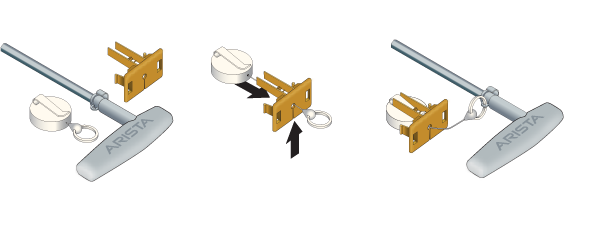
Use the following steps to attach the tethering mechanism to the extraction tool.
- Extend and slip the lanyard thread through the slot in the plastic tether.
- Attach the ring to the extraction tool.
- Plug the plastic tether into one of the slots.
- Repeat for the other tools as appropriate.
Power Supplies
Removing AC Power Supply
- Put on a grounded, anti-static ESD strap.
- Unplug the cable(s) by squeezing the cable release. Up to two cables could be powering each PSU.
- Squeeze the latch release.
- Remove the power supply from the switch using the power supply latch release and handle.
Installing AC Power Supply
- Put on a grounded, anti-static ESD strap.
- Unpack the new power supply.
- Insert the new power supply into the empty power supply slot.
- After you insert the power supply, push gently on the power supply until the power supply is fully seated.
- Connect the power cord(s) to the power supply. Up to two cables can power each PSU.
- Connect to the power source.
- Verify normal operation using the LED indicators for your switch Table 13 - AC Power Supply Status LED States.
Removing DC Power Supply
- Remove power from DC circuits by turning off the power line servicing the circuits.
- Make sure to remove the ground connection last when removing power.
- Put on a grounded, anti-static ESD strap.
- Disconnect the power cable from the DC power source.
- Squeeze the latch release.
- Remove the power supply from the switch using the power supply latch release and handle.
- Remove each power cable lug to the terminal studs with the flange locking nuts.
- Remove the flange locking nuts to each of the terminal studs.
- Disconnect the power cable lug from the terminal studs.
Installing DC Power Supply
Removing Power Supply Blank
Fabric and Fan Module (Fabric Module)
The fabric and fan modules are hot-swappable and accessible from the switch's rear panel (Rear Panel). You must consider that the module you are inserting is compatible with the switch and the module you are replacing. Perform the following steps to remove and replace a fabric and fan module or a fan-only module if your switch supports one.
Removing Fabric Module
- Pull out the ejector levers on the fabric module.
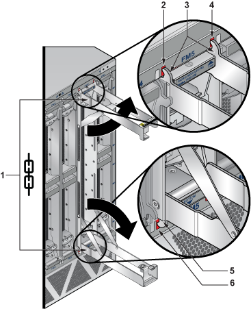
1 Fabric module ejector levers 3 Fabric module ejector claws 5 Fabric module ejector claw 2 Claw position on chassis 4 Claw position on chassis 6 Claw position on chassis
Installing Fabric Module
- Slide the module into the open slot until the injector claw touches the chassis's rear face.
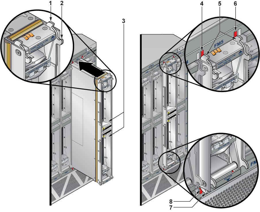
1 Fabric module top right injector claw 4 Claw position on chassis 7 Fabric module bottom left injector claw 2 Fabric module top right ejector claw 5 Fabric module top injector claws 8 Claw position on chassis 3 Fabric module ejector levers 6 Claw position on chassis - Fully open the ejector levers at 90 degrees and seat the module.
Note: The ejector claws should be touching the rear face of the chassis.
1 Fabric module ejector levers 3 Fabric module seating claws 5 Fabric module seating claw 2 Claw position on chassis 4 Claw position on chassis 6 Claw position on chassis - Close the ejector levers in unison.
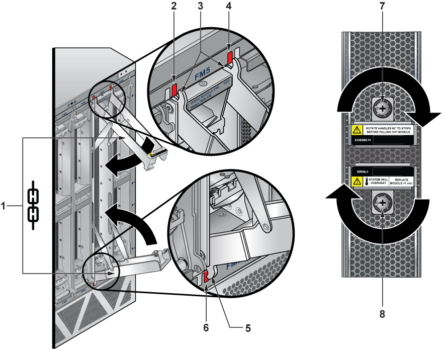
1 Fabric module ejector levers 4 Claw position on chassis 7 Screw 2 Claw position on chassis 5 Fabric module ejector claw 8 Screw 3 Fabric module ejector claws 6 Claw position on chassis CAUTION: Ensure that the claws engage correctly on the chassis.
Fan Module (within Fabric Module)
The fabric and fan modules are hot-swappable and accessible from the switch's rear panel (Rear Panel). You must ensure that the module you insert is compatible with the switch and the module you are replacing. Perform the following steps to remove and replace a fan module that is part of the fabric module.
- Remove the fabric module with the fan to be replaced (Removing Fabric Module).
- Place the fabric module on a flat work surface. A cart or table designated for such tasks is typically appropriate.
- Locate the failed fan and
- Push the green latch, then
- Rotate the fan lever to the open position.
Note: See figure below.
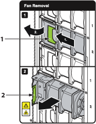
1 Release latch 2 Fan lever - Lift the fan straight up and out of the fabric module.
- Insert the replacement fan straight down and into the fabric module.
- Rotate the fan lever to the closed position.
- Ensure that the green latch has securely slid into the latched and locked position.
- Reinstall the fabric module into the chassis (Installing Fabric Module).
Supervisor Module
The supervisor modules are hot-swappable and accessible from the front of the switch. You must consider that the module you are inserting is compatible with the switch and the module you are replacing. Use the following procedure to remove and replace a supervisor module. For the supervisor module locations for your device, refer to the Front Panel.
Removing Supervisor Module
Installing Supervisor Module
- Put on a grounded, anti-static ESD strap.
- Unpack the supervisor module to be installed.
- Slide the supervisor module into the slot.
- Lock the supervisor module using the tool supplied (Front Panel).
- Verify that the module is operating normally (Table 1 - Supervisor Status LED States).
Removing Supervisor Module Blank
Linecards
The linecards are hot-swappable and accessible from the front of the switch. You must consider that the linecard you are inserting is compatible with the switch and the linecard you are replacing. Use the following procedure to remove and replace a linecard. If you are adding a new linecard, remove the blank from the linecard slot and install the new linecard. For the linecard locations on your switch, refer to the Front Panel.