External Antenna Ports on C-130E
Make sure theantennas are connected to the respective RP-SMA type of connector ports as shown below:
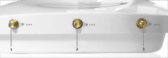
Make sure theantennas are connected to the respective RP-SMA type of connector ports as shown below:
Describes the supported AC power supplies and lists the power cables you can use to connect the supply to a power source.
| Label | Description |
|---|---|
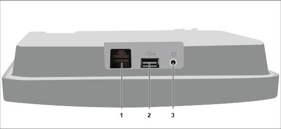
| 1 | Console (Ethernet) |
| 2 | USB |
| 3 | Reset |
|
Port |
Description |
Connector Type |
Speed/Protocol |
|---|---|---|---|
|
Ethernet |
To establish 'Config Shell' terminal session via serial connection. |
RJ45 |
|
|
USB |
USB 2.0 port |
Not in use |
Not in use |
|
Reset Pinhole |
Reset to factory default settings |
Pin hole push button |
Hold down and power cycle the device to reset |
The Reset Pin Hole and the USB port are on the top side of the device as shown in the figure above. The Reset Pinhole resets the C-130E device to factory defaults. To reset the device, press and hold the Reset Pin Hole for 10 sec until all LEDs go off which indicates that the device has rebooted. Pressing the Reset Pin Hole while the device is booting up will not have any effect. You should perform this operation only when the device is running.
When you reset the device, the following settings are reset:
The USB port on the C-130E is currently not in use.
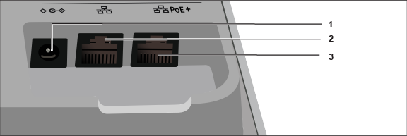
The rear panel of the C-130E provides an PoE+ Ethernet port that enables you to connect the device to a wired LAN through a switch or a hub and power the device by using the 802.3af/802.3at standard.
| Label | Description |
|---|---|
| 1 | Power (DC IN) |
| 2 | LAN2 |
| 3 | LAN1 |
|
Port |
Description |
Connector Type |
Speed/Protocol |
|---|---|---|---|
|
DC IN |
Enables you to connect to and power on device using 12V DC power with 2.0 ampere. |
6.3 mm barrel |
-- |
|
Ethernet (LAN2) |
Gigabit Ethernet port that can be used for wired extension for an SSID. |
RJ45 |
10/100/1000 Mbps Gigabit Ethernet |
|
Ethernet (LAN1/PoE+) |
Gigabit Ethernet port used to connect to the wired LAN and communicate with the Mojo Cloud or Server. This port can also be used to power the device using the 802.3af Power over Ethernet (PoE+) standard. |
RJ45 |
If using PoE (802.3af) some features will be disabled |
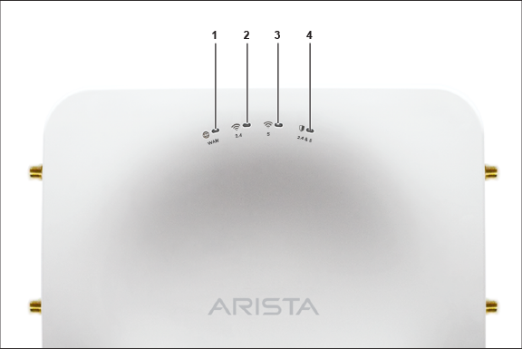
The front panel of the C-130E has 4 functional LEDs that indicate the working of the device.
| Label | Description |
|---|---|
| 1 | Power |
| 2 | 2.4 GHz Radio |
| 3 | 5 GHz Radio |
| 4 | Third Radio |
Power LED: The following table describes the Power LED states.
| Green | Orange | |
| Solid | Running at full capability | Running at reduced capability |
| Blinking | Received IP address, but not connected to the server | Did not receive an IP address |
Reduced capability indicates that the AP is getting lower than the required maximum power from the PoE switch, i.e., 802.3af instead of 802.3at.
Radio LEDs: ON when the corresponding radio is operational.
C-130E is a 4x4 802.11a/b/g/n/ac access point with three radios.
This chapter provides an overview of the C-130E and describes:
The access point (AP) package must contain the components shown in the following figure.
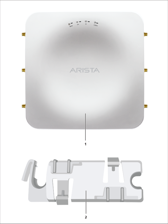
| Label | Description |
|---|---|
| 1 | C-130E Access Point |
| 2 | 15/16" (24 mm) Mounting Bracket |
If the package is not complete, please contact Arista Networks Technical Support Team at support-wifi@arista.com, or return the package to the vendor or dealer where you purchased the product.
This installation guide explains how to deploy the C-130E access point (AP).
Installing the AP constitutes your acceptance of the terms and conditions of the EULA mentioned above in this document.
This guide can be referred by anyone who wants to install and configure the C-130E access point.
This guide contains the following chapters:
To receive important news on product updates, please visit our website at https://www.arista.com/en/support/product-documentation. We continuously enhance our product documentation based on customer feedback.
www.arista.com
DOC-03484-02
|
Headquarters
5453 Great America Parkway
Santa Clara, CA 95054, USA +1-408 547-5500 www.arista.com
|