Front View of the System
This section contains the following topics:
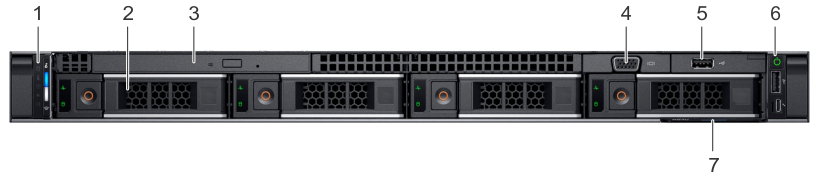
This front view displays the features available on the front of the CloudVision Appliance.
| Item | Ports, panels, and slots | Icon | Description |
| 1 | Left control panel | N/A | Contains the system health and system ID, status LED, and the iDRAC Quick Sync 2 (wireless) indicator.
Note: The iDRAC Quick Sync 2 indicator is available only on certain configurations.
|
| 2 | Drive slots | N/A | Enables you to install drives that are supported on your system. |
| 3 | Optical drive (optional) | N/A | One optional slim SATA DVD-ROM drive or DVD+/-RW drive. |
| 4 | VGA port | Enables you to connect a display device to the system. | |
| 5 | USB port (optional) | The USB port is USB 2.0 compliant. | |
| 6 | Right control panel | N/A | Contains the power button, USB port, iDRAC Direct micro port, and the iDRAC Direct status LED. |
| 7 | Information Tag | N/A | The Information Tag is a slide-out label panel that contains system information such as Service Tag, NIC, MAC address, and so on. If you have opted for the secure default access to iDRAC, the Information tag also contains the iDRAC secure default password. |
| Icon | Description | Condition | Corrective Action |
| Drive Indicator | The indicator turns solid amber if there is a drive error. |
|
|
| Temperature Indicator | The indicator turns solid amber if the system experiences a thermal error (for example, the ambient temperature is out of range, or there is a fan failure). | Ensure that none of the following conditions exist:
|
|
| Electrical Indicator | The indicator turns solid amber if the system experiences an electrical error (for example, voltage out of range, or a failed power supply unit (PSU) or voltage regulator). | Check the System Event Log or system messages for the specific issue. If it is due to a problem with the PSU, check the LED on the PSU. Reseat the PSU. | |
| Memory Indicator | The indicator turns solid amber if a memory error occurs. | Check the System Event Log or system messages for the location of the failed memory. Reseat the memory module. | |
| PCIe Indicator | The indicator turns solid amber if a PCIe card experiences an error. | Restart the system. Update any required drivers for the PCIe card. Reinstall the card. |
The iDRAC Direct LED indicator lights up to indicate that the port is connected and is being used as a part of the iDRAC subsystem.
You can configure iDRAC Direct by using a USB to micro USB (type AB) cable, which you can connect to your laptop or tablet. The following table describes iDRAC Direct activity when the iDRAC Direct port is active:
| iDRAC Direct LED Indicator Code | Condition |
| Solid green for two seconds. | Indicates that the laptop or tablet is connected. |
| Flashing green (on for two seconds and off for two seconds). | Indicates that the laptop or tablet connected is recognized. |
| Turns off. | Indicates that the laptop or tablet is unplugged. |
iDRAC Quick Sync 2 module (optional) is located on the left control panel of your system.

| iDRAC Quick Sync 2 indicator code | Condition | Corrective action |
|---|---|---|
| Off (default state) | Indicates that the iDRAC Quick Sync 2 feature is turned off. Press the iDRAC Quick Sync 2 button to turn on the iDRAC Quick Sync 2 feature. | If the LED fails to turn on, reseat the left control panel flex cable and check. |
| Solid white | Indicates that iDRAC Quick Sync 2 is ready to communicate. Press the iDRAC Quick Sync 2 button to turn off. | If the LED fails to turn off, restart the system. |
| Blinks white rapidly | Indicates data transfer activity. | |
| Blinks white slowly | Indicates that firmware update is in progress. | |
| Blinks white five times rapidly and then turns off | Indicates that the iDRAC Quick Sync 2 feature is disabled. | Check if iDRAC Quick Sync 2 feature is configured to be disabled by iDRAC. |
| Solid amber | Indicates that the system is in fail-safe mode. | Restart the system. |
| Blinking amber | Indicates that the iDRAC Quick Sync 2 hardware is not responding properly. | Restart the system. |
Pre-installation Checklist
To set up single node CVP, complete the following steps.
Assign to each of the three CVP VMs a role (primary, secondary or tertiary).
To assign the roles, complete the following steps.
After CVP is running on the multi-node appliance cluster, enter the CVP Web Interface of the primary node via its CVP IP/Hostname with default username/password of cvpadmin/cvpadmin to set the password.
For Multi-node clusters, setting the password only has to be done on one node, and is synced to other nodes so subsequently any node can be accessed via its web interface. Refer to the CloudVision Configuration Guide for instructions on using CVP.
The system's LCD panel provides system information and status and error messages to indicate if the system is operating correctly or if the system needs attention.
The LCD back-light lights blue during normal operating conditions.
When the system needs attention, the LCD lights amber and displays an error code followed by descriptive text.
The LCD back-light turns OFF when the system is in standby mode and can be turned on by pressing either the Select, Left, or Right button on the LCD panel.
The LCD back-light remains OFF if LCD messaging is turned off through the iDRAC utility, the LCD panel, or other tools.
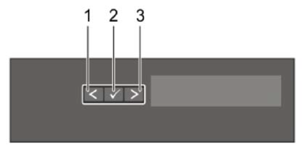
| Item | Button | Description |
|---|---|---|
| 1 | Left | Moves the cursor back in one-step increments. |
| 2 | Select | Selects the menu item highlighted by the cursor. |
| 3 | Right | Moves the cursor forward in one-step increments.
During message scrolling:
|
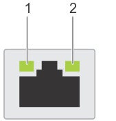
Each NIC on the back of the system has indicators that provide information about the activity and link status. The activity LED indicator indicates if data is flowing through the NIC, and the link LED indicator indicates the speed of the connected network.
| Status | Condition |
| Link and activity indicators are off. | The NIC is not connected to the network. |
| Link indicator is green, and activity indicator is blinking green. | The NIC is connected to a valid network at its maximum port speed and data is being sent or received. |
| Link indicator is amber and activity indicator is blinking green. | The NIC is connected to a valid network at less than its maximum port speed and data is being sent or received. |
| Link indicator is green, and activity indicator is off. | The NIC is connected to a valid network at its maximum port speed and data is not being sent or received. |
| Link indicator is amber and activity indicator is off. | The NIC is connected to a valid network at less than its maximum port speed and data is not being sent or received. |
| Link indicator is blinking green and activity is off. | NIC identify is enabled through the NIC configuration utility. |
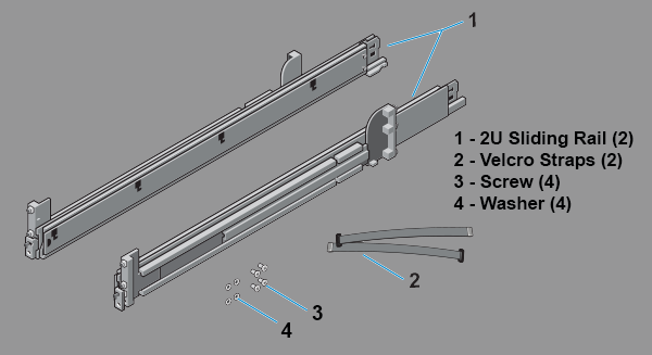
The two-post rack mount kit includes:
AC power supply units (PSUs) have an illuminated translucent handle that serves as an indicator. The indicator shows whether power is present or if a power fault has occurred.
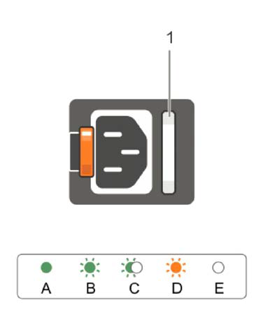
| Power Indicator Codes | Condition |
| Green | A valid power source is connected to the PSU, and the PSU is operational. |
| Blinking amber | Indicates a problem with the PSU. |
| Not illuminated | Power is not connected to the PSU. |
| Blinking green | When the firmware of the PSU is being updated, the PSU handle blinks green.
CAUTION: Do not disconnect the power cord or unplug the PSU when updating the firmware. If the firmware update is interrupted; the PSUs do not function.
|
| Blinking green and turns off | When hot-plugging a PSU, the PSU handle blinks green five times at a rate of 4 Hz and turns off. This indicates a PSU mismatch concerning efficiency, feature set, health status, or supported voltage.
CAUTION: If two PSUs are installed, both the PSUs must have the same type of label; for example, Extended Power Performance (EPP) label. Mixing PSUs from previous generations of PowerEdge servers is not supported, even if the PSUs have the same power rating. This results in a PSU mismatch condition or failure to turn the system on.
CAUTION: When correcting a PSU mismatch, replace only the PSU with the blinking indicator. Swapping the PSU to make a matched pair can result in an error condition and unexpected system shutdown. To change from a high output configuration to a low output configuration or vice versa, you must turn off the system.
CAUTION: AC PSUs support both 240 V and 120 V input voltages except for Titanium PSUs, which support only 240 V. When two identical PSUs receive different input voltages, they can output different wattage, and trigger a mismatch.
CAUTION: If two PSUs are used, they must be of the same type and have the same maximum output power.
|
This section reviews the following topics: