RoHS Declaration Statements
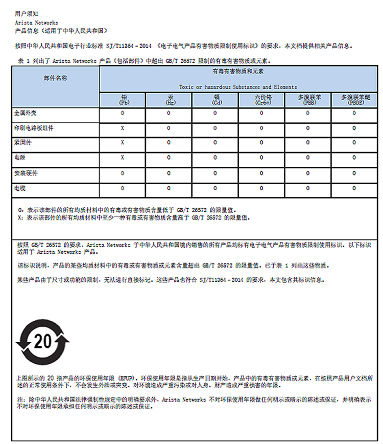
For Taiwan BSMI RoHS Table, go to https://www.arista.com/assets/data/pdf/AristaBSMIRoHS.pdf.
For Taiwan BSMI RoHS Table, go to https://www.arista.com/assets/data/pdf/AristaBSMIRoHS.pdf.
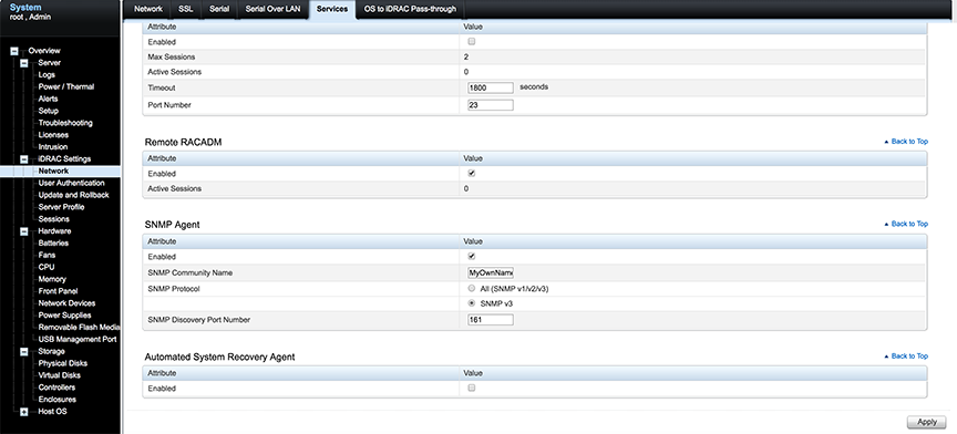
To locate the SNMP support page, go to iDRAC Settings > Network > Services.
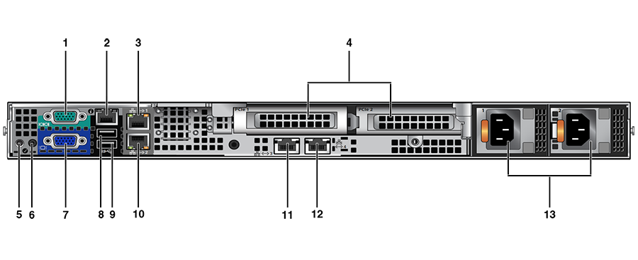
This section displays the back panel of the CloudVision Appliance.
| Number | Indicator, Button, or Connector | Description |
| 1 | Serial connector | Allows you to connect a serial device to the system. |
| 2 | iDRAC port (optional) | Dedicated management port on the iDRAC ports card. |
| 3 | Ethernet connector 1 | Integrated 10/100/1000 Mbps NIC connector. |
| 4 | PCIe expansion card slots (2) | Allows you to connect a PCI Express expansion card. |
| 5 | System identification button | The identification buttons on the front and back panels can be used to locate a particular system within a rack. When one of these buttons is pressed, the system status indicator on the back flashes until one of the buttons is pressed again.
Press to toggle the system ID on and off. If the system stops responding during POST, press and hold the system ID button for more than five seconds to enter BIOS progress mode. To reset the iDRAC (if not disabled in F2 iDRAC setup) press and hold the button for more than 15 seconds. |
| 6 | System identification connector | Connects the optional system status indicator assembly through the optional cable management arm. |
| 7 | Video connector | Allows you to connect a VGA display to the system. |
| 8 | USB connector | Allows you to connect USB devices to the system. The port is USB 2.0-compliant. |
| 9 | USB connector | Allows you to connect USB devices to the system. The port is USB 3.0-compliant. |
| 10 | Ethernet connector 2 | Integrated 10/100/1000 Mbps NIC connector. |
| 11 | Ethernet connector 3 | Integrated 10/100/1000 Mbps NIC connector. |
| 12 | Ethernet connector 4 | Integrated 10/100/1000 Mbps NIC connector. |
| 13 | Power supplies (PSU1 and PSU2) | One supplied 550 W redundant Platinum AC power supply. (Option of one additional power supply available.) |
A number of tools are available to help manage and update images and insert ISO to the Virtual Machine (VM).
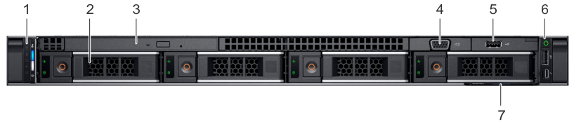
This front view displays the features available on the front of the CloudVision Appliance.
| Item | Ports, panels, and slots | Icon | Description |
| 1 | Left control panel | N/A | Contains the system health and system ID, status LED, and the iDRAC Quick Sync 2 (wireless) indicator.
Note: The iDRAC Quick Sync 2 indicator is available only on certain configurations.
|
| 2 | Drive slots | N/A | Enables you to install drives that are supported on your system. |
| 3 | Optical drive (optional) | N/A | One optional slim SATA DVD-ROM drive or DVD+/-RW drive. |
| 4 | VGA port | Enables you to connect a display device to the system. | |
| 5 | USB port (optional) | The USB port is USB 2.0 compliant. | |
| 6 | Right control panel | N/A | Contains the power button, USB port, iDRAC Direct micro port, and the iDRAC Direct status LED. |
| 7 | Information Tag | N/A | The Information Tag is a slide-out label panel that contains system information such as Service Tag, NIC, MAC address, and so on. If you have opted for the secure default access to iDRAC, the Information tag also contains the iDRAC secure default password. |
Arista provides an executable that will update all packages in the CVA.
To upgrade a single node CVA, perform all the steps listed in Steps to Upgrade the CVA. After the CVA host comes up, and after rebooting the system from the last step of upgrade, allow 20 minutes for the CVP application to be accessible again.
Perform a rolling upgrade to update the CVA systems in multi-node configuration. Perform all the steps listed in section Steps to Upgrade the CVA from the start to finish on only one of the CVAs at a time. After the upgrade, wait for all the VMs, (CVP and CVX) to be fully up and running (CVP takes 20 minutes to be up from reboot). Verify that the CVP is accessible. After the verification, proceed to upgrade the second CVA host in a similar fashion and then the third CVA.
Complete the following steps:
CloudVision VMs virtual disks are shipped in qcow2 format with by default, a data disk size of 1TB. For better scale and performance, it is recommended that the virtual disks be converted to raw format, and data disk expanded to a size more appropriate to the expected cale. At max scale supported today we recommend a 4.5TB /data disk.
Example
/cva/scripts/cvaDiskUtil.py[status]
Example
/cva/scripts/cvaDiskUtil.py makeraw [--quiet]
/cva/scripts/cvaDiskUtil.py expand [--disk-size DISK_SIZE] DISK_SIZE can be in KB, MB, GB or TB