Status Indicators
This section discusses the following topics:
Each AC power supply has an illuminated translucent handle that indicates whether power is present or whether a power fault has occurred.
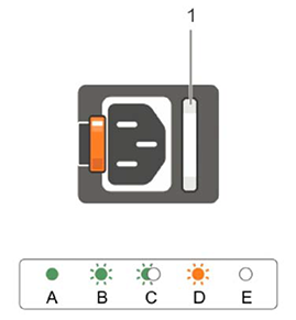
| OK LED | Status |
| Green | A valid power source is connected to the power supply and the power supply is operational. |
| Flashing green | When updating the firmware of the power supply unit is being updated, the power supply handle flashes green. |
| Flashing green and turns off | When hot-adding a power supply, the power supply handle flashes green five times at 4 Hz rate and turns off. This indicates that there is a power supply mismatch with respect to efficiency, feature set, health status, and supported voltage. Replace the power supply with a power supply that matches the capacity of the other power supply. |
| Flashing amber | Indicates a problem with the power supply. |
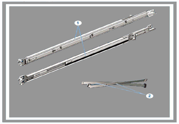
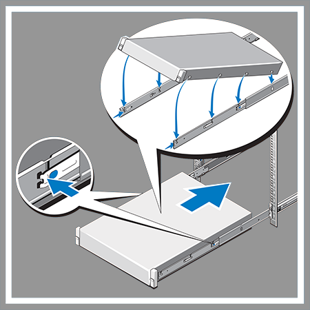
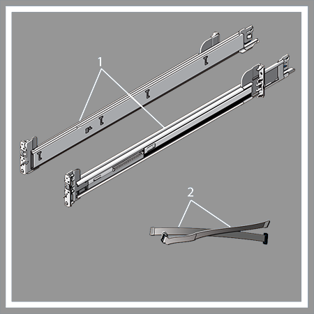
Each appliance provides an accessory kit that contains parts that are required to install the appliance.
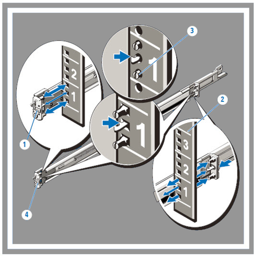
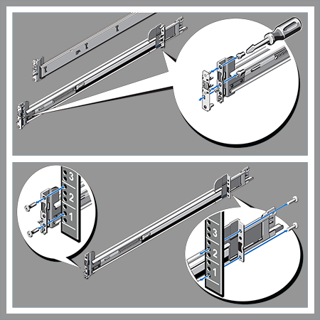
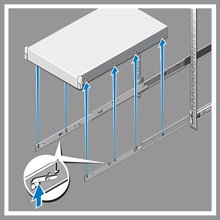
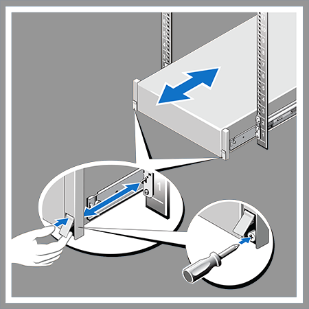
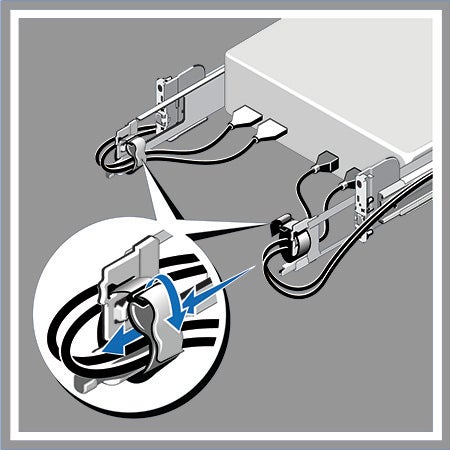
Use the following steps to assemble the racking rails and attaching the components to the system.
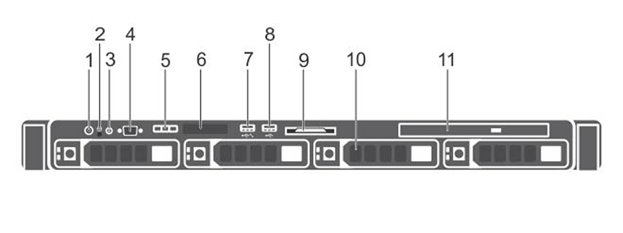
This section displays the front panel of the DCA-CV-100 CloudVision Appliance.
| Number | Indicator, Button, or Connector | Description |
| 1 | Power-on Indicator, Power button. | The power-on indicator lights when the system power is on. The power button controls the power supply output to the system. Note: On ACPI-compliant operating systems, turning off the system using the power button causes the system to perform a graceful shutdown before power to the system is turned off. |
| 2 | NMI button | Used to troubleshoot software and device driver errors when running certain operating systems. This button can be pressed using the end of a paper clip. Note: Important! Use this button only if directed to do so by qualified support personnel. |
| 3 | System Identification button | The identification buttons on the front and back panels can be used to locate a particular system within a rack. When one of these buttons is pressed, the system status indicator on the back flashes until one of the buttons is pressed again. Press to toggle the system ID on and off. If the system stops responding during POST, press and hold the system ID button for more than five seconds to enter BIOS progress mode. To reset the iDRAC (if not disabled in F2 iDRAC setup) press and hold the button for more than 15 seconds. |
| 4 | Video Connector | Allows you to connect a display to the system. |
| 5 | Diagnostic Indicators | The diagnostic indicator lights up to display error status. |
| 6 | LCD Panel | Displays system ID, status information, and system error messages. |
| 7 | USB Management Port/iDRAC Managed USB Port | The USB Management Port can function as a regular USB port or provide access to the iDRAC features. |
| 8 | USB Connector | Allows you to connect USB devices to the system. The port is USB 2.0-compliant. |
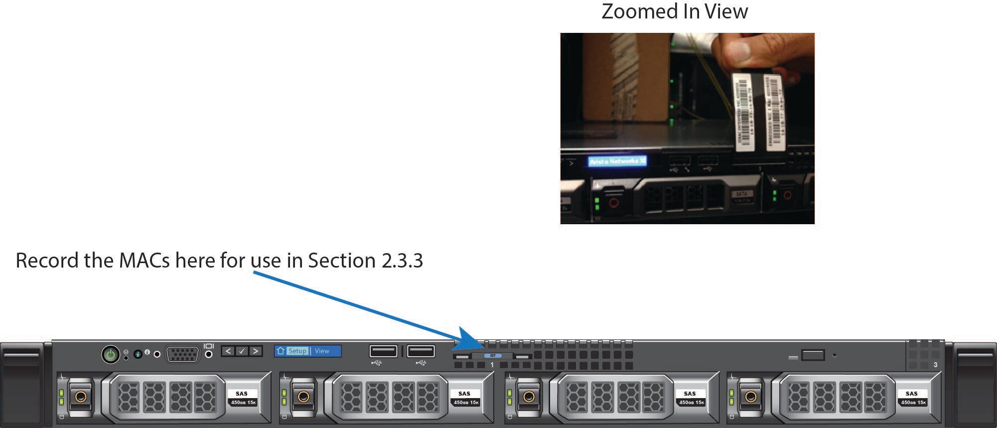
| 9 | Information Tag | A slide-out label panel which contains system information such as Service Tag, NIC, MAC address, and so on for your reference. |
| 10 | Hard Drives | Up to four 3.5 inch hot-swappable hard drives/SSDs. |
| 11 | Optical Drive (optional) | One optional slim SATA DVD-ROM drive or DVD+/-RW drive. |
Arista provides an ISO with all updated packages and a tool to mount the images ISO and upgrade the system.
Use the following procedure to upgrade a single-node CV Appliance configuration.
Complete the following steps to upgrade single-node CV Appliance configurations.
A rolling upgrade should be done when upgrading multi-node CV Appliance configurations.
The steps you use are exactly the same as the steps used for single-node configurations, except that you must repeat the procedure for each node.
CVP takes approximately 20 minutes to be fully accessible after the system reboot (running the upgrade script, which is done near the end of the procedure, automatically reboots the system). Verify that CVP is accessible before you begin to upgrade the next CV Appliance host in your multi-node cluster configuration.
Complete the following steps to upgrade multi-node CV Appliance configurations.
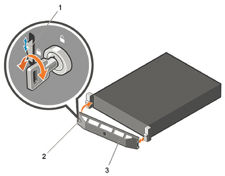
Removing the front bezel:
| Legend | |
| 1 | Release Latch |
| 2 | Key-lock |
| 3 | Front Bezel |
The information tag is a slide-out label which contains system information such as Service Tag, NIC, MAC address for your reference. Record the MAC addresses in the CloudVision Worksheet.
On the back panel of the DCA-CV-100 CloudVision appliance, locate the Ethernet Integrated 10/100/1000 Mbps NIC connectors.
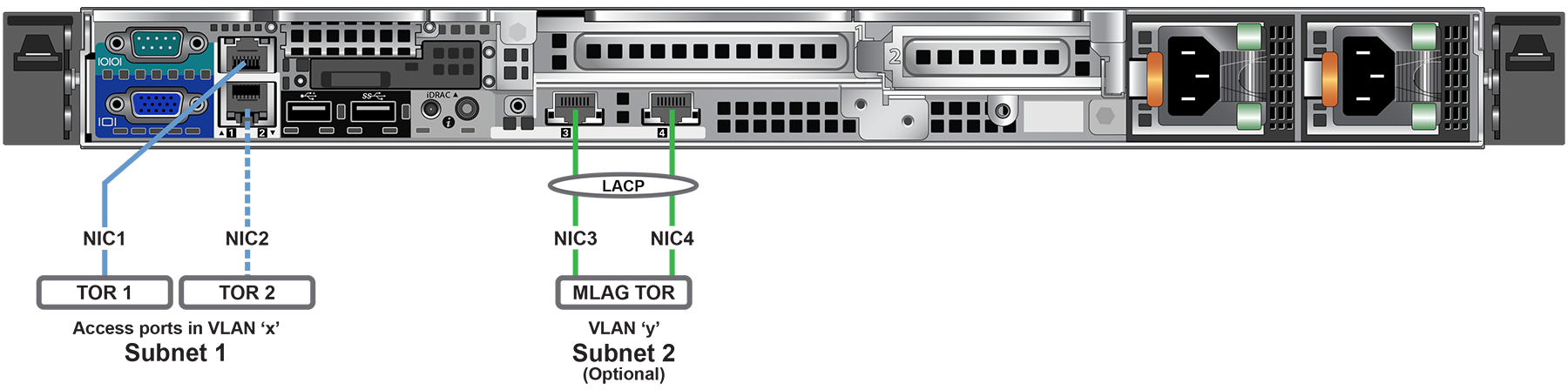
iDRAC is an Intelligent Platform Management Interface (IPMI) that provides a GUI-based out-of-band interface for monitoring the hardware appliance. iDRAC uses NIC1 (see Figure 2-4) for its network connectivity using a unique MAC address.
Record the IP address and Hostname information in CloudVision Worksheet (see Appendix H).
Contact your DNS zone administrator for assistance.
The CloudVision Appliance Host and iDRAC IP addresses can be allocated in either of two ways:
Using the iDRAC MAC from Locate the MAC Addresses for the CloudVision Appliance (see Figure 2), input an entry into the DHCP Server for the corresponding iDRAC IP address mapping to that MAC.
Using the HOST NIC1 MAC from Locate the MAC Addresses for the CloudVision Appliance (see Figure 2), input an entry into the DHCP Server for the corresponding HOST IP address mapping to that MAC.
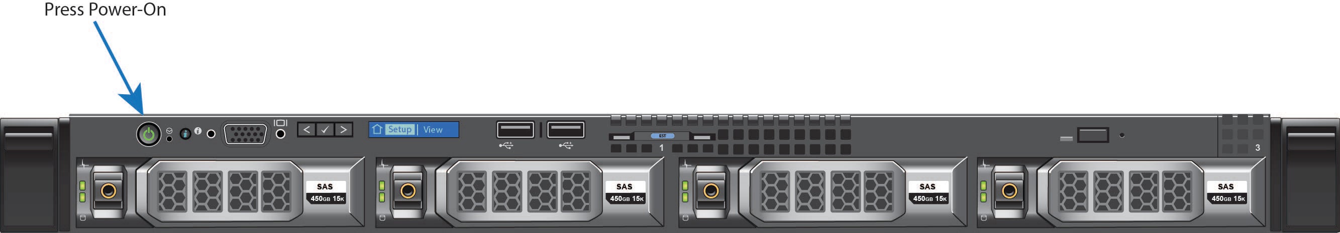
Turn the system on by pressing the power button located on the front of the system.
The iDRAC IP address can be manually configured via the host's bash shell using the racadm tool. The racadm commands below are sequence dependent and must be entered in the following order.
The host IP address can be manually configured via the host's bash shell. In order for the settings to be persistent, the following configuration must be completed.