Cabling the Switch
Connecting Power Cables
Important! Installation of this equipment must comply with local and national electrical codes. If necessary, consult with the appropriate regulatory agencies and inspection authorities to ensure compliance.
The switch operates with two installed power supplies. At least one power supply must connect to a circuit that provides 100-240 VAC, 50 or 60 Hz, and 5.29 A. Two circuits provide redundancy protection. The switch uses power cables that comply with IEC-320 and have a C13 plug. The accessory kit provides two IEC-320 C13 to C14 power cables, each two meters long.
Figure 4-1 displays the power socket in the power supply modules that are located on the rear panel. Appendix E displays the location of the power supplies on the panel.
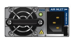
Figure 4-1: Power Supply Socket
Important! Read all installation instructions before connecting the system to the power source.
• Non-Redundant Configuration: Connect a power cord to either of the two power supply inputs.
• Redundant Power Supply Configuration: Connect power cords to both power supply inputs.
• Power down the Switch: Remove all power cords from the power supply inputs.
Important! This equipment must be grounded. Never defeat the ground conductor.
Important! This unit requires overcurrent protection.
Connecting Serial and Management Cables
The accessory kit includes the following cables:
• RJ-45 to DB-9 serial adapter cable.
• RJ-45 Ethernet cable.
The front panel contains the console, management, and USB ports. Figure 4-2 displays the ports on the 7124SX switch. Appendix D displays the front panel of all switches covered by this guide.
Use the provided cables to connect the front panel ports:
• Console (Serial) Port: Use the RJ-45 to DB-9 serial adapter cable to connect the console (serial) port to a PC. The switch uses the following default settings:
• 9600 baud
• No flow control
• 1 stop bit
• No parity bits
• 8 data bits
• Ethernet Management Port: Use the RJ-45 Ethernet cable to connect the Ethernet management port to a 10/100/1000 management network.
• USB Port: The USB port may be used for software or configuration updates.
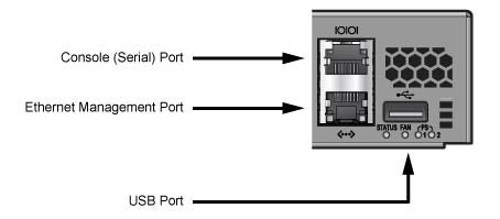
Figure 4-2: Front Panel Ports
Caution Excessive bending can damage interface cables, especially optical cables.