Mounting the Switch
Important! The rack mounting procedure is identical for all switches covered by this guide. Illustrations in this chapter depict the mounting of a DCS-7124SX switch.
The accessory kit provides components for installing the switch in two-post and four-post racks.
• Section 3.1 provides instructions for mounting the switch in a two-post rack.
• Section 3.2 provides instructions for mounting the switch in a four-post rack.
Both options require the attachment of mounting brackets to the switch chassis. Each chassis side contains six pairs of holes that align with bracket holes. Bracket hole orientation is symmetric, allowing bracket placements where the flange is flush with the front or rear switch panel (Figure 3-1).
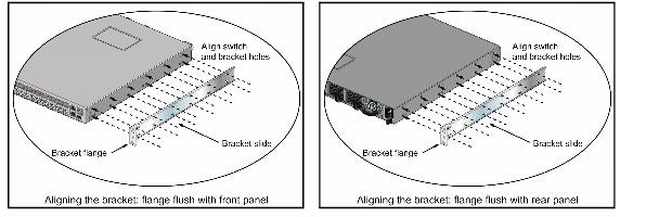
Figure 3-1: Chassis and Mounting Bracket Alignment for Front and Rear Rack Mounts
Bracket holes are horizontally equidistant, allowing bracket placements where the flange is not flush with either panel (Figure 3-2). This placement supports a center-rack mount.
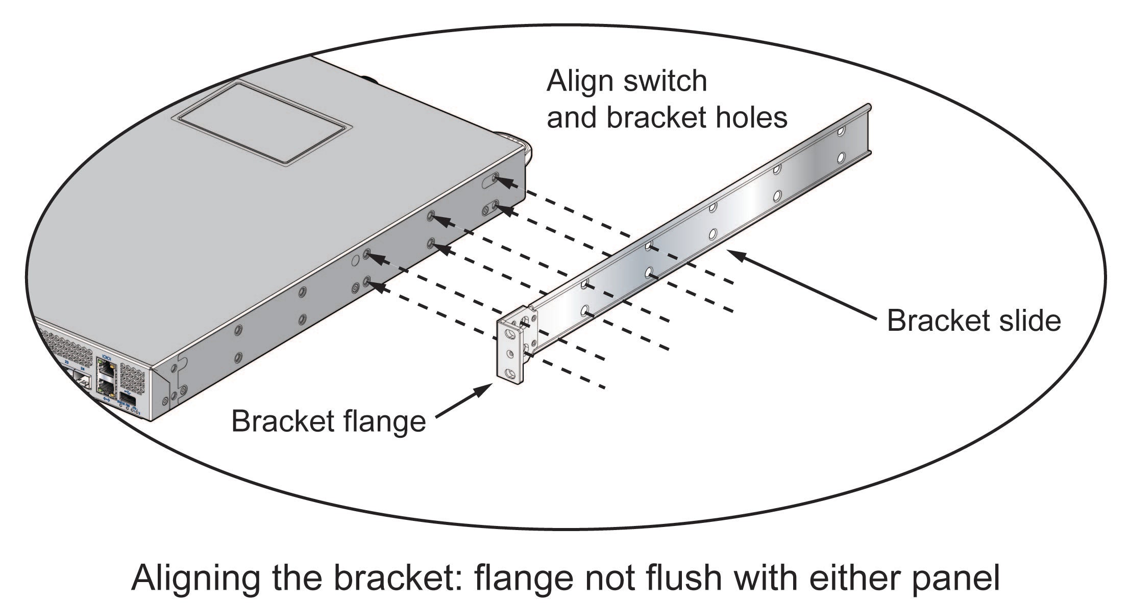
Figure 3-2: Chassis and Mounting Bracket Alignment for Center Rack Mount
After completing the instructions for your rack type, proceed to Chapter 4.
Two-Post Rack Mount
To mount the switch onto a two-post rack, assemble the mounting brackets to the chassis, then attach the brackets to the rack posts. The accessory kit includes the following two-post mounting parts:
• 2 mounting brackets
• 12 M4x5 flat head Phillips screws
Refer to Figure 3-1 and Figure 3-2 for a description of the mounting brackets.
The switch supports any mounting position into a two-post rack that meets the following conditions:
• The bracket flanges do not extend beyond the switch chassis.
• Three sets of screws attach each mounting bracket to the chassis.
Figure 3-3 displays proper bracket mount configuration examples. Figure 3-4 displays improper bracket mount configuration examples.
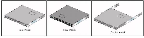
Figure 3-3: Bracket Mount Examples for Two-Post Rack Mount
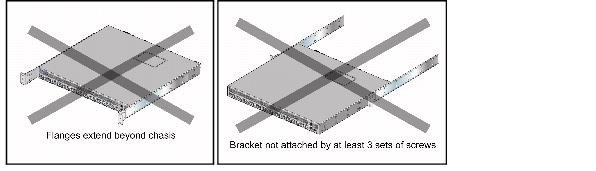
Figure 3-4: Improper Bracket Mount Examples for Two-Post Rack Mount
Attaching Mounting Brackets to the Chassis
To attach mounting brackets to the switch chassis, perform this procedure:
Step 1 Align the mounting brackets with the chassis to obtain the desired mounting position.
Step 2 Attach the brackets with six M4x5 flat head Phillips screws per bracket, using a #1 Phillips screwdriver.
Space the screws evenly, separating them with the widest possible distance. Figure 3-5 displays screw placement for the front and center mount positions.

Figure 3-5: Attaching the Mounting Brackets to the Switch Chassis
Inserting the Switch into the Rack
Step 1 Lift the chassis into the rack. Position the flanges against the rack posts.
Figure 3-6 displays the front-mount switch installation.
Step 2 Select mounting screws that fit your equipment rack.
Step 3 Attach the bracket flanges to the rack posts.
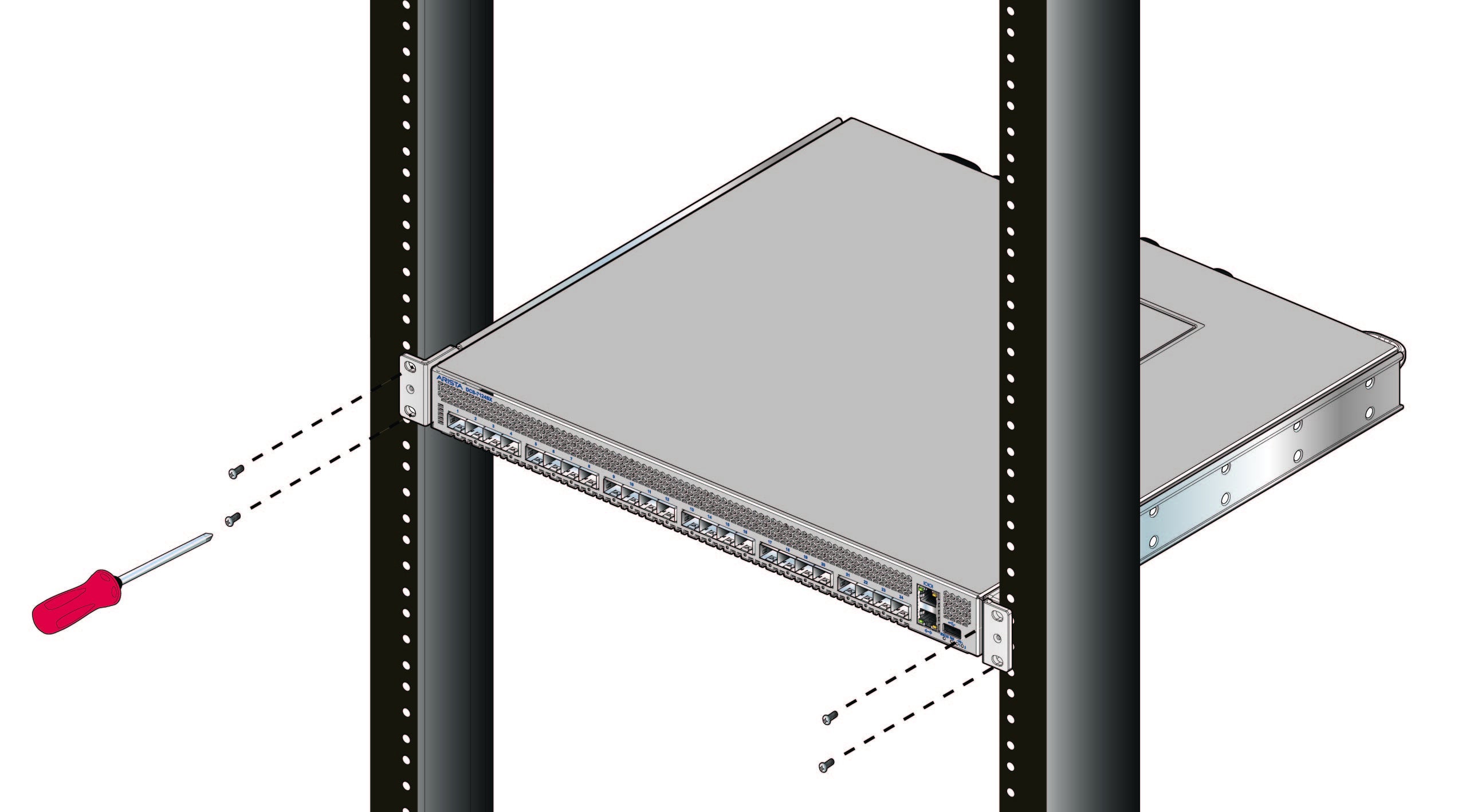
Figure 3-6: Inserting the Switch into the Rack
After completing the two-post rack mount, proceed to Chapter 4.
Four-Post Rack Mount
The switch is mounted onto a four-post rack by assembling two rails onto the rear posts, sliding the switch onto the rails, then securing the switch to the front post.
The installation kit provides the following four-post mounting parts:
• 2 mounting brackets
• 2 rails
• 12 M4x5 flat head Phillips screws
Refer to Figure 3-1 and Figure 3-2 for a description of the mounting brackets.
The switch supports any mounting position where at least three sets of screws attach each mounting bracket to the switch chassis.
Figure 3-7 displays proper bracket mount configuration examples. Figure 3-8 displays an improper bracket mount configuration example.
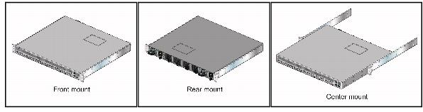
Figure 3-7: Bracket Mount Examples for Four-Post Rack Mount
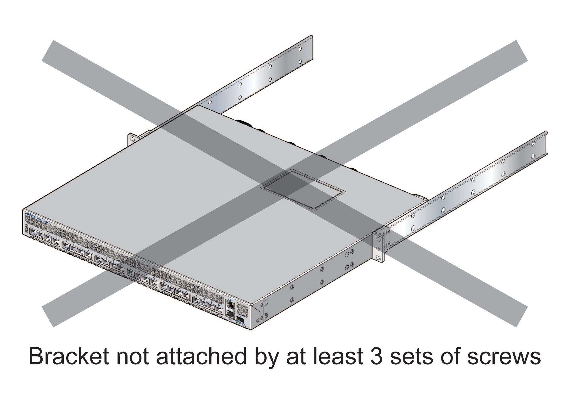
Figure 3-8: Improper Bracket Mount Example for Four-Post Rack Mount
Attaching Mounting Brackets to the Chassis
To attach mounting brackets to the switch chassis, perform this procedure:
Step 1 Align the mounting brackets with the chassis to obtain the desired mounting position.
Step 2 Attach the brackets with six M4x5 flat head Phillips screws per bracket, using a #1 Phillips screwdriver.
Space the screws evenly, separating them with the widest possible distance. Figure 3-9 displays screw placement for the front mount and center mount positions.
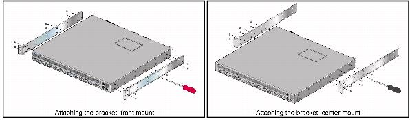
Figure 3-9: Attaching the Mounting Brackets to the Switch Chassis
Assembling the Rails onto the Equipment Rack
The rails attach to the rear rack posts to support the switch. Before attaching the rails to the rack posts, verify that, when the switch is mounted, the distance between the bracket flanges and rail flanges does not exceed 30 inches, as shown in Figure 3-10.

Figure 3-10: Maximum Bracket-Rail Span
To attach the rails to the rear rack post, perform this procedure:
Step 1 Select mounting screws that fit your equipment rack. Each rail requires two screws.
Step 2 Attach the rails to the rear rack posts, as shown in Figure 3-11.
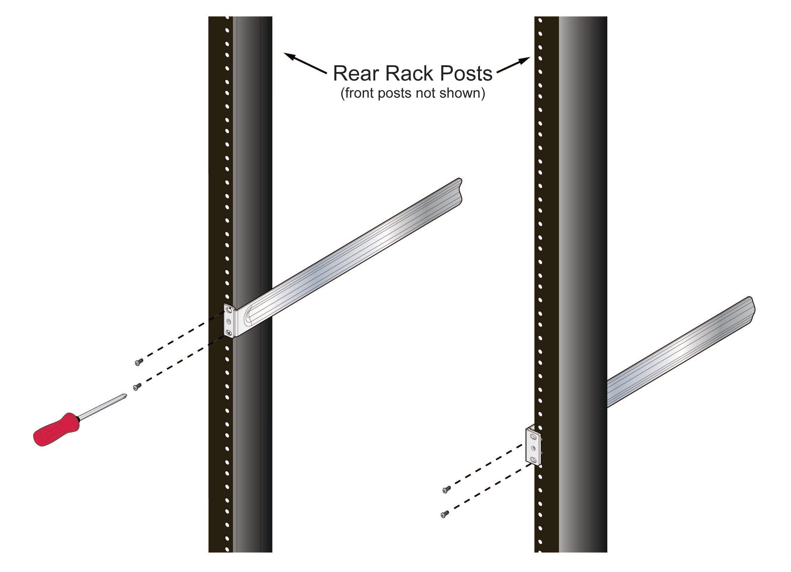
Figure 3-11: Attaching the Rails, as viewed from Rear of Rack
Attaching the Switch to the Rack
Step 1 Lift the switch into the rack and insert the mounting brackets onto the rails.
Step 2 Slide the switch on the rails, toward the rear posts, until the mounting bracket flanges are positioned on the rail posts (Figure 3-12).
Step 3 Select mounting screws that fit the equipment rack. Each chassis side requires two screws.
Step 4 Verify the distance between the mounting bracket flanges and rail flanges does not exceed 30 inches (see Figure 3-10).
Step 5 Attach the bracket flanges to the rack posts (Figure 3-13).
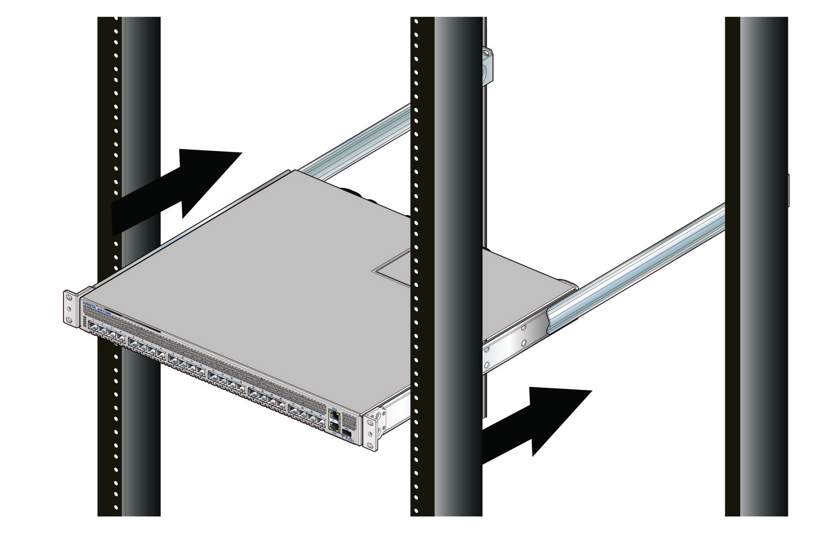
Figure 3-12: Inserting the Switch onto the Rails
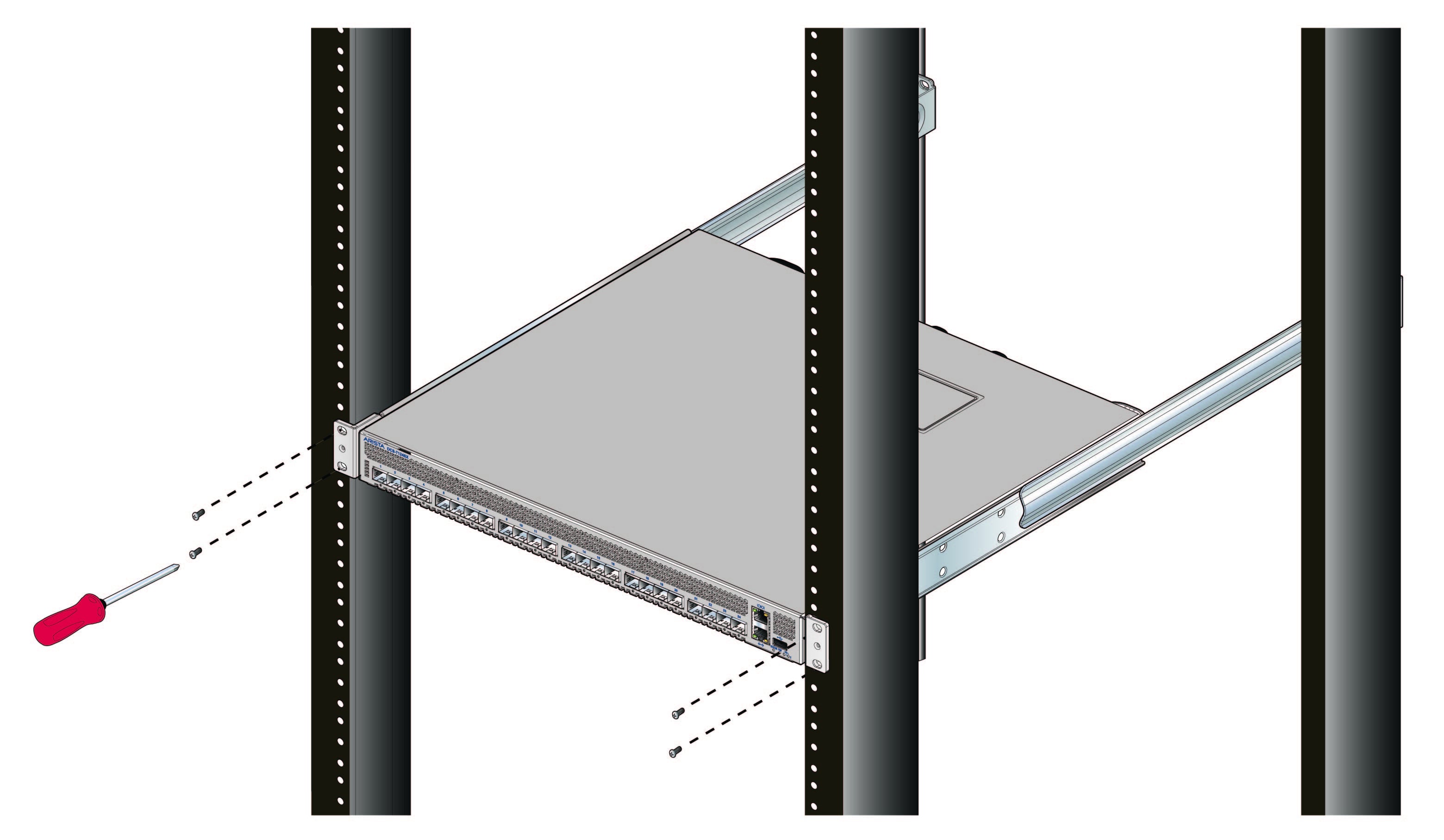
Figure 3-13: Attaching the Switch to the Rack Posts
After completing the four-post rack mount, proceed to Chapter 4.