Overview
Scope
This guide intends for properly trained service personnel and technicians who need to install the DMF Service Node Appliance.
Supplemental Documentation
Refer to the Arista EOS User manual or additional configuration requirements at https://www.arista.com/en/support/product-documentation.
Obtaining Technical Assistance
All customers, partners, resellers, or distributors holding a valid Arista Service Contract can obtain technical support in any of the following ways:
-
Email: This email address is being protected from spambots. You need JavaScript enabled to view it.
Include a detailed problem description and the “show tech-support” output.
-
Web: https://www.arista.com/en/support
Create a support case through the support portal on our website. You may also download the most current software and documentation and view FAQs, Knowledge Base articles, Security Advisories, and Field Notices.
-
Phone: +1 866-476-0000 or +1 408-547-5502
Safety Information
Refer to the Arista Networks document Safety Information and Translated Safety Warnings at: https://www.arista.com/en/support/product-documentation.
Specifications
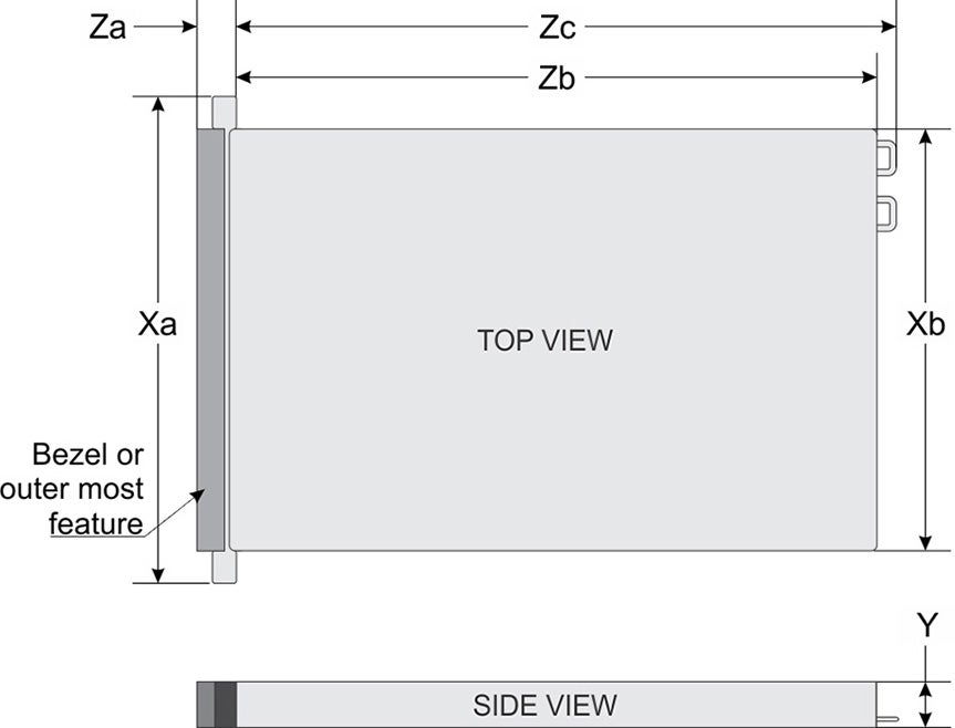
| System | Dimensions |
|---|---|
| Xa | 482.0 mm (18.97 inches) |
| Xb | 434.0 mm (17.08 inches) |
| Y | 42.8 mm (1.685 inches) |
| Za | 35.84 mm (1.41 inches) (with bezel)
22 mm (0.87 inches) (without bezel) |
| Zb | 677.1 mm (26.65 inches) (Ear to rear wall) |
| Zc | 712.95 mm (28.05 inches) (Ear to PSU handle without velcro strap) |
| System Configuration | Maximum weight (with all drives/SSDs) |
|---|---|
| 4 x 3.5-inch | 19.45 kg |
| No backplane configuration | 15.38 kg |
| Power Draw | Specifications |
|---|---|
| Power Draw (Typical) 550 W AC | Platinum 50/60 Hz 100 240 V AC, auto-arranging |
| Power Draw (Typical) 450 W AC | Bronze 50/60 Hz 100 240 V AC, auto-arranging |
| Temperature | Specifications |
|---|---|
| Non-operational | -40°C to 65°C (-40°F to 149°F) |
| Temperature ranges (For Altitude <900 meters or 2953 feet) | 5°C to 45°C (41°F to 113°F) with no direct sunlight on the equipment. |
| Maximum temperature gradient (operating and non-operational) | 20°C in an hour* (36°F in an hour) and 5°C in 15 minutes (9°F in 15 minutes), 5°C in an hour* (9°F in an hour) for tape hardware. |
| Relative Humidity | Specifications |
|---|---|
| Non-operational | 5% to 95% RH with 27°C (80.6°F) maximum dew point. The atmosphere must be non-condensing at all times. |
| Operational | 8% RH with -12°C (10.4°F) minimum dew point to 90% RH with 24°C (75.2°F) maximum dew point. Non-condensing at all times. |
| Maximum Vibration | Specifications |
|---|---|
| Operating | 0.21 Grms at 5 Hz to 500 Hz for 10 minutes (all operational orientation) |
| Storage | 1.88 Grms at 10 Hz to 500 Hz for 15 min (all six sides tested) |
| Maximum Shock | Specifications |
|---|---|
| Operating | 6 G six consecutively shock pulses in the positive and negative x, y, and z axes up to 11 ms. |
| Storage | 71 G six consecutively shock pulses in the positive and negative x, y, and z axes (one pulse on each side of the system) up to 2 ms. |
| Maximum Altitude | Specifications |
|---|---|
| Operational | 3050 m (10,006 ft) |
| Non-operational | 12,000 m (39,370 ft) |
| Standard Operating Temperature | Specifications |
|---|---|
| Continuous operation (for altitude less than 950 m or 3117 ft). | 10°C to 35°C (50°F to 95°F) with no direct sunlight on the equipment. |