DMF GUI REST API Inspector

Overview

DANZ Monitoring Fabric (DMF) 8.6 introduces a newly designed API Inspector available on all DMF UI pages. Previously, the former API Inspector was accessible by selecting the Dragonfly icon, and it was only available on some pages.

Launch the API Inspector

  1. Hover over and select the User icon to see the drop-down menu.
  2. Select API Inspector to open the API Inspector table.
  3. The REST API Inspector table appears between the page content and the navigation bar. It will remain open when switching between pages.
  4. To close it, select API Inspector or the × icon.
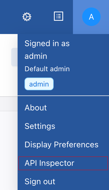
Figure 1. Menu > API Inspector

Figure 2. REST API Inspector

API Requests Tab

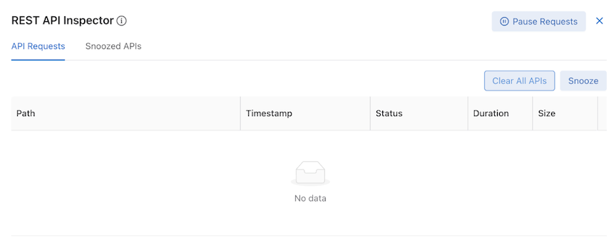
API Requests contains a table displaying all recent API requests and several utility buttons.
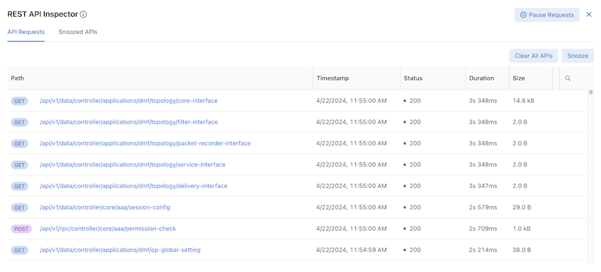
Figure 3. API Requests Tab

API Requests Table

Each row contains specific API request information:

  • Path – HTTP request method and URL
  • Timestamp – date and approximate time
  • Status – HTTP response codes
  • Duration – time taken to receive a response
  • Size – response body size

The table logs the latest 500 API requests and automatically updates when new API calls are received.

Search

The table's results are searchable. Selecting the magnifying glass icon displays a Type to Search line in the first row.

Figure 4. Search by Column

The table supports search by Path, HTTP Method, and Status column contexts.


Interaction

Selecting a URL expands specific API requests and enters the Detailed API Request View.

Pause Requests Button

Use Pause Requests to stop tracking new API requests. An alert message appears next to the REST API Inspector title.

During the pause, the button changes to Resume Requests. To resume tracking API requests, select Resume Requests. The table updates accordingly.

Note: Any requests made during the pausing state are not retrieved.
Figure 5. Paused Requests

Clear All APIs Button

To clear the entire table, select Clear All APIs.
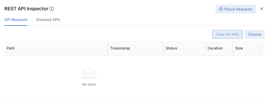
Figure 6. Cleared Table

The Snoozed API table is not affected. API Inspector continues receiving and displaying new requests in the table.

Snooze Button

Using Snooze makes the table rows selectable, and the Snooze button changes to Snooze Selected APIs. Clicking Cancel or Snooze Selected APIs returns the table entries to an unselected state.

Figure 7. API Requests

During the selectable state, select specific API Requests and select Snooze Selected APIs to prevent them from appearing in the table.

Snoozed APIs Tab

Snoozed APIs display all snoozed API requests.

Snoozed APIs Table

The snoozed APIs table is empty by default.
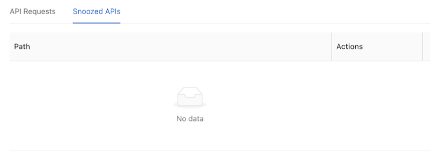
Figure 8. Snoozed APIs Default Table

The table displays snoozed APIs. However, unlike the API Requests table, the Snoozed API table only distinguishes API requests by URL and HTTP Method. Requests with the same URL only appear once in the Snoozed API Table.
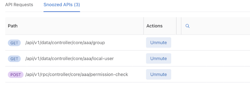
Figure 9. Snoozed APIs

Search

The table's results are searchable. Selecting the magnifying glass icon displays a Type to Search line in the first row.

Figure 10. Type to Search

The Snoozed APIs table supports search by Path columns contexts only.

Unmute Button

Unmute resumes tracking the API request and updates the table. Any requests with the same URL that occur going forward are added to the API requests table.

Detail API Requests View

Selecting a URL in the API Requests table expands that specific API request and enters the Detail API Requests view.
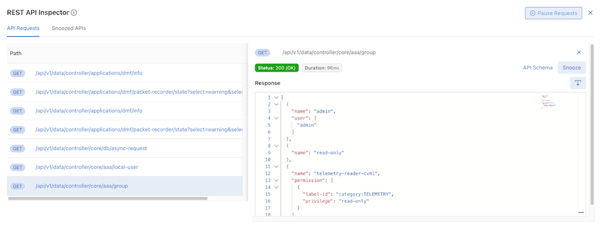
Figure 11. Detailed API Requests View

The UI displays a truncated API Requests table and a detailed view; selecting another URL changes the detailed information in the detailed view.

Information on the selected API request includes:

  • HTTP methods – show the HTTP methods

  • Response status – show the response status and response text

  • Duration – show the duration of the API request

  • API Schema link button – Open a new tab to the API Schema Browser Page

  • Snooze – Snooze this selected API request (same as Snooze Button )

  • Response – Show all the response information of this selected API request

  • Download Icon – Download response information into a .json file.

Note: For PATCH / POST / PUT requests, another field, Request Body, shows the request body information.
  • Use the download icon to download the request body information into a .json file.
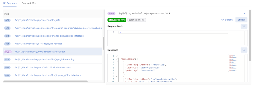
Figure 12. Download JSON File
  • API Inspector obfuscates sensitive values such as password, hash ID, hash password, auth session, encode result, and secret by replacing them with ********.
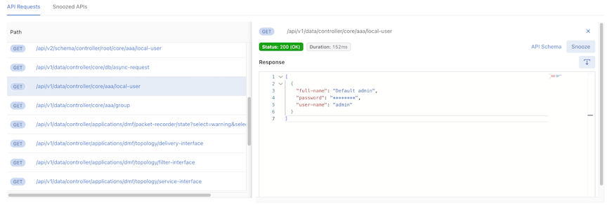
Figure 13. Obfuscated Sensitive Data
 

DMF Controllers in Google Cloud VMware Engine

The DANZ Monitoring Fabric (DMF) Controller in Google Cloud VMware Engine (GCVE) supports the operation of the Arista Networks DMF Controller on the GCVE platform and uses the vCenter portal to launch the Virtual Machine (VM) running the DMF Controller.

The DMF Controller in GCVE enables the registration of VM deployments in the vCenter environment and supports auto-firstboot when deployed using the Deploy OVF Template wizard in the vCenter.

Configuration

GCVE portal provides the vCenter server IP address with the credential details. Log in to the vCenter using these credentials to deploy the Controller VM using the Deploy OVF Template wizard in the vCenter.

The following describes using the wizard to deploy the Controller VM.

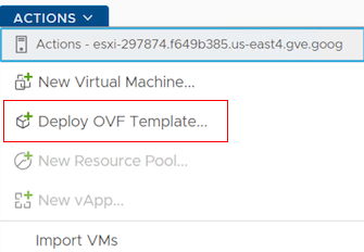
  1. In VMware vCenter, navigate to the Actions menu and select Deploy OVF Template.
    Figure 1. Deploy OVF Template
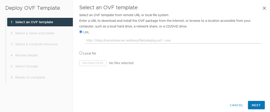
  2. The Deploy OVF Template wizard appears.
    Figure 2. Deploy OVF Template Wizard
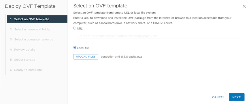
  3. Enter the URL for the OVA file. If the OVA file is available locally on the machine, choose the Local file option and select Upload Files.
    Figure 3. Enter URL or Local File
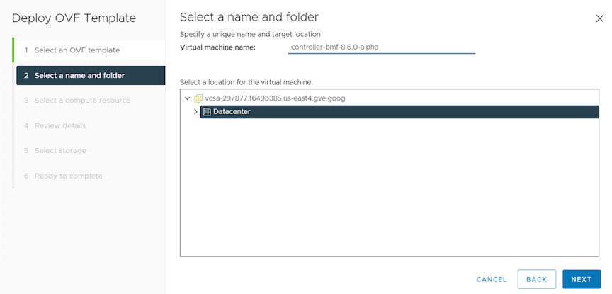
  4. Provide the Virtual machine name and select its location.
    Figure 4. Virtual Machine Name
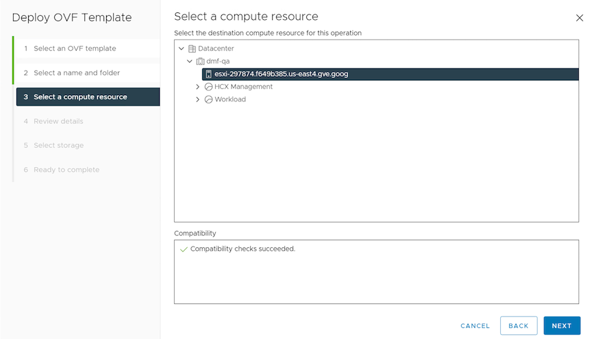
  5. Select the destination compute resource.
    Figure 5. Compute Resource
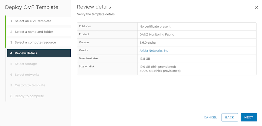
  6. Review details summarize the OVA file details.
    Figure 6. Review Details
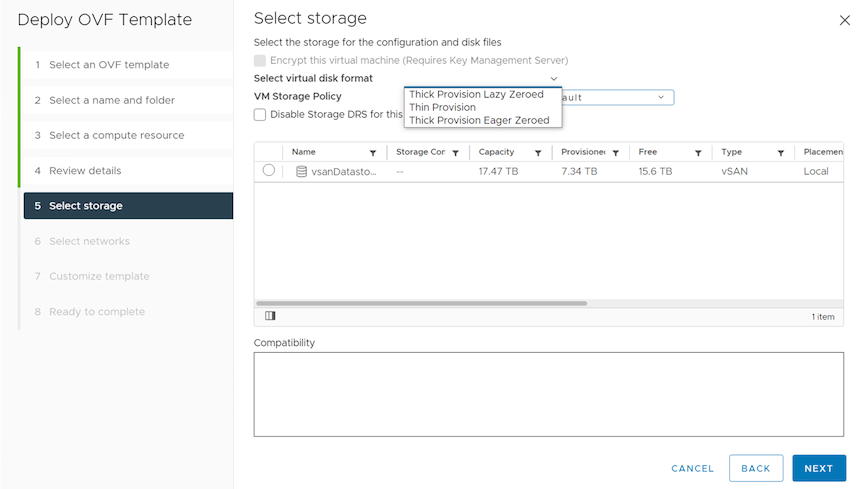
  7. Provide the storage details for the VM.
    Figure 7. Storage Details
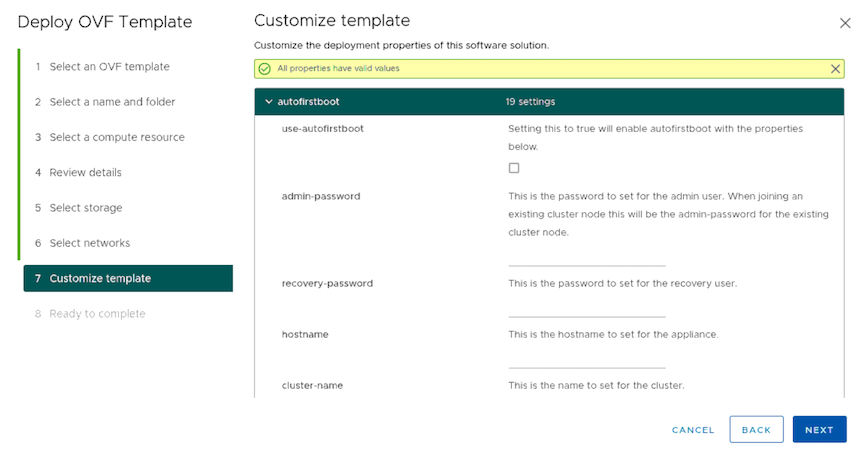
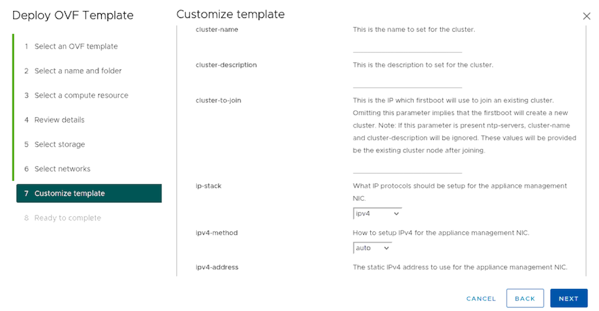
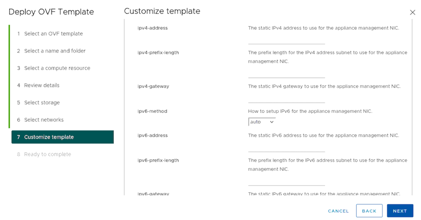
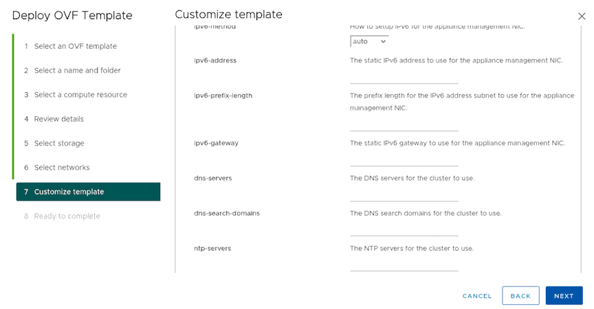
  8. As illustrated in the following Customize template sections, autofirstboot parameters appear. Use these parameters to configure the VM to make it ready after the OVF deployment. There are 19 settings; however, some are mandatory, while others are optional.
    Figure 8. Customize Template Auto First Boot – 19 Settings


    Figure 9. Customize Template Auto First Boot


    Figure 10. Customize Template Auto First Boot


    Figure 11. Customize Template Auto First Boot
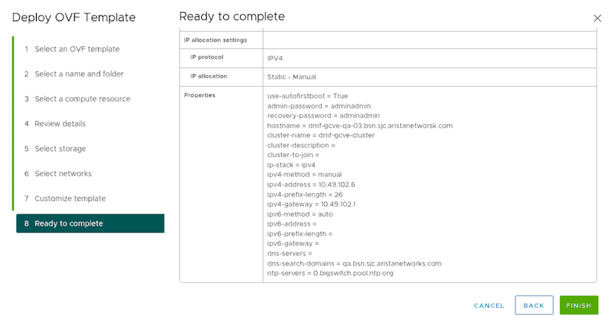
  9. Review the Ready to complete firstboot parameters and select Finish to enter the configuration. If changes are required, select Back and make those changes.
    Figure 12. Ready To Complete

Firstboot Parameters

The following table lists the firstboot parameters for the auto-firstboot configuration.

Required Parameters

Key Description Valid Values
admin_password This is the password to set for the admin user. When joining an existing cluster node this will be the admin-password for the existing cluster node. string
recovery_password This is the password to set for the recovery user. string

Additional Parameters

Key Description Required Valid Values Default Value
hostname This is the hostname to set for the appliance. no string  
cluster_name This is the name to set for the cluster. no string  
cluster_to_join This is the IP which firstboot will use to join an existing cluster. Omitting this parameter implies that the firstboot will create a new cluster. Note: If this parameter is present ntp-servers, cluster-name, and cluster-description will be ignored. The existing cluster node will provide these values after joining. no IP Address String  
cluster_description This is the description to set for the cluster. no string  

Networking Parameters

Key Description Required? Valid Values Default Value
ip_stack What IP protocols should be set up for the appliance management NIC. no enum: ipv4, ipv6, dual-stack ipv4
ipv4_method How to setup IPv4 for the appliance management NIC. no enum: auto, manual auto
ipv4_address The static IPv4 address used for the appliance management NIC. only if ipv4-method is set to manual IPv4 Address String  
ipv4_prefix_length The prefix length for the IPv4 address subnet to use for the appliance management NIC. only if ipv4-method is set to manual 0..32  
ipv4_gateway The static IPv4 gateway to use for the appliance management NIC. no IPv4 Address String  
ipv6_method How to set up IPv6 for the appliance management NIC. no enum: auto, manual auto
ipv6_address The static IPv6 address to use for the appliance management NIC. only if ipv6-method is set to manual IPv6 Address String  
ipv6_prefix_length The prefix length for the IPv6 address subnet to use for the appliance management NIC. only if ipv6-method is set to manual 0..128  
ipv6_gateway The static IPv6 gateway to use for the appliance management NIC. no IPv6 Address String  
dns_servers The DNS servers for the cluster to use no List of IP address strings  
dns_search_domains The DNS search domains for the cluster to use. no List of the hostnames or FQDN strings  
ntp_servers The NTP servers for the cluster to use. no List of the hostnames of FQDN strings:

0.bigswitch.pool.ntp.org

1.bigswitch.pool.ntp.org

2.bigswitch.pool.ntp.org

3.bigswitch.pool.ntp.org

Post Installation Verification

  1. Access a DMF Controller VM using an SSH login session.
  2. Verify the Controller clusters have formed using the show controller command.
    GCVE-DMF-860-1# ​​show controller
    Cluster Name : GCVE-DMF-860-1
    Cluster Description: GCVE DMF CONTROLLER
    Cluster Virtual IP : 10.100.189.231
    Redundancy Status: redundant
    Last Role Change Time: 2024-05-21 14:23:38.917000 PDT
    Failover Reason: Changed connection state: connected to node 21773
    Device deployment mode : pre-configured
    Cluster Uptime : 1 day, 3 hours
    # Hostname @ State Uptime
    -|--------------|-|-------|-------------------|
    1 GCVE-DMF-860-1 * active5 hours, 6 minutes
    2 GCVE-DMF-860-2 standby 15 minutes, 11 secs
    GCVE-DMF-860-1#
  3. Use the show version command to verify the installed version is correct.
    GCVE-DMF-860-1# show version
    Controller Version : DANZ Monitoring Fabric 8.6.0 (bmf/dmf-8.6.0 #10)
    GCVE-DMF-860-1#

Troubleshooting

The following are possible failure modes:
  • auto-firstboot fails due to a transient error or bug.
  • auto-firstboot parameter validation fails.
To debug these failures, connect to the VM using the console, log in as user recovery, and use the following command to review the firstboot logs.
recovery@dmf-controller-0-vm:~$ less /var/log/floodlight/firstboot/firstboot.log
To debug parameter validation errors, access the parameter validation results using the following command.
recovery@dmf-controller-0-vm:~$ less /var/lib/floodlight/firstboot/validation-results.json

Limitations

  • There is no support for capture interfaces in GCVE.

CloudVision DMF Integration

This chapter describes integrating CloudVision with the DANZ Monitoring Fabric (DMF).

Overview

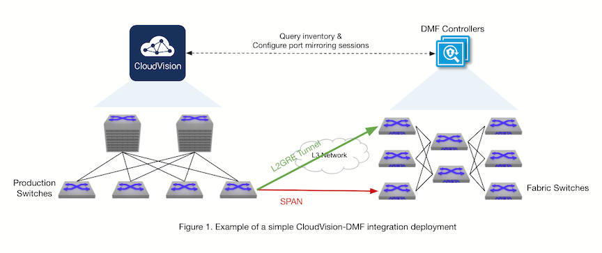
In a typical CloudVision-DMF integration deployment, CloudVision Portal (CVP) deploys alongside the DANZ Monitoring Fabric (DMF). The DMF Controller communicates with CVP to retrieve its managed device inventory and configures port mirroring sessions on any CVP-managed production devices that are Arista Extensible Operating System (EOS) switches.

Configuration on the DMF Controller provides the information necessary to communicate with CVP: the CVP hostname or IP address and user credentials.

Policy configuration on the DMF Controller specifies what to monitor in the production network managed by CVP, such as the production switches, the switch interfaces to monitor traffic from, and the direction of mirrored traffic (bidirectional, ingress, or egress). In addition, the configuration on the DMF Controller can define whether to use a Switch Port Analyzer (SPAN) session or a Layer-2 Generic Routing Encapsulation (L2GRE) tunnel session on a CVP-managed device. When using SPAN, the DMF configuration includes the switch interface to monitor traffic. When using L2GRE, the DMF configuration includes monitoring traffic to the Tunnel End Point (TEP).

Figure 1. Simple CloudVision-DMF Integration Deployment

The preceding figure illustrates a simple CloudVision-DMF integration configuration where CloudVision Portal and DMF can communicate with each other. DMF monitors traffic from CVP directly to one of its fabric switches (a filter switch), as indicated by the red arrow labeled “SPAN.” DMF also monitors traffic from CVP to a TEP configured on the fabric using an L2GRE tunnel, as indicated by the green arrow labeled “L2GRE Tunnel". Since DMF initiates monitoring using policy configuration, the policies monitoring CVP will handle the traffic according to their configuration, for example, forwarding it to a delivery interface. This feature enables the automation of the creation, modification, and deletion of filter interfaces and tunnel interfaces in DMF and mirroring sessions on CVP-managed devices.

Compatibility Requirements

EOS Platform Compatibility CloudVision Compatibility
  • On-premise 2024.2.0 and newer is recommended.
CloudVision Requirements
  • The user configured in DMF for CVP integration must have sufficient permissions in CVP. The minimum permissions required are:
    • Devices: Read access to inventory management.
    • gNMI: Read and write access to the gNMI service.
  • Register the devices that DMF will monitor for use in Studios using the Inventory and Topology Studio.

CloudVision DMF Integration using the CLI

To integrate with CloudVision Portal, configure a CVP instance in the DMF Controller, enabling communication between CVP and DMF. The CVP hostname or IP address must be reachable from the DMF Controller. If CVP is a multi-node system, using a hostname that will resolve to the primary node is recommended to maintain the connection in case of a primary node failure. The user in the CVP integration configuration must have at least the permissions in CloudVision as outlined in CloudVision Requirements.

Configure using the CLI

Configure a CVP instance on the DMF Controller using the following series of commands:
dmf-controller(config)# cvp cvp_instance_name
dmf-controller(config-cvp)# host-name cvp_hostname_or_ip
dmf-controller(config-cvp)# username username
dmf-controller(config-cvp)# password password
Add a description to the CVP instance using the description command, as required.
dmf-controller(config-cvp)# description description_of_cvp_instance
Refresh the connection between DMF and CVP with the sync command, which sends a request to CVP to re-authenticate the connection and to re-fetch the inventory:
dmf-controller(config)# sync cvp cvp_instance_name

To use L2GRE tunnels in the integration, enable tunneling in the DMF Controller and set the match mode to one of the following that is compatible with tunneling: full-match or l3-l4-offset-match. Configure tunnel endpoints to allow monitoring from CVP to DMF using an L2GRE tunnel; add a tunnel endpoint to a policy configuration or to a CVP integration instance's configuration to optionally define a default tunnel endpoint for this instance.

Before the DMF 8.5 release, the following command string was mandatory:
dmf-controller(config)# tunnel-endpoint tep_name switch fabric_switch fabric_switch_interface ip-address tep_ip mask subnet_mask gateway gateway_ip
However, starting with DMF 8.5.0, the mask and gateway parameters in the tunnel-endpoint command are now optional. Thus, configure a tunnel endpoint using the following command:
dmf-controller(config)# tunnel-endpoint tep_name switch fabric_switch fabric_switch_interface ip-address tep_ip
To set a default tunnel endpoint for a CVP integration instance, use the following commands:
dmf-controller(config)# cvp cvp_instance_name
dmf-controller(config-cvp)# default-tunnel-endpoint tep_name
To remove a default tunnel endpoint for a CVP integration instance, use the following commands:
dmf-controller(config)# cvp cvp_instance_name
dmf-controller(config-cvp)# no default-tunnel-endpoint tep_name

Starting with the DMF 8.6.0 release, a configuration flag called preserve-mirror-sessions per CVP instance indicates whether mirroring sessions will be preserved for the CVP instance when uninstalling DMF policies configured with it. By default, the flag is false, meaning existing mirroring sessions are automatically removed if the relevant DMF policies are uninstalled.

Enable preserving mirroring sessions using the preserve-mirror-sessions command.
dmf-controller(config-cvp)# preserve-mirror-sessions
Conversely, disable preserving mirroring sessions (default behavior) using the no preserve-mirror-sessions command.
dmf-controller(config-cvp)# no preserve-mirror-sessions

Monitoring Configuration in Policies

DMF uses policies to create, update, or remove the monitoring of CVP-managed devices. DMF supports monitoring multiple CVP instances, switches, and interfaces as mirroring sources in a single policy or across policies. Configure the mirrored traffic direction to one of the following settings:

  • bidirectional (default)
  • ingress
  • egress
After enabling CVP integration in a DMF policy (i.e., adding a CVP instance as a traffic source), the DMF Controller will automatically create filter interfaces and tunnel interfaces, with origination "auto-generated." A mirroring session is automatically created on the CVP-managed switch; DMF does this via the mirroring Studio and the change control process on CVP.
Note: If a DMF-managed mirroring session exists on a switch for one DMF policy with identical sources and the same destination as needed for another DMF policy, both policies use the same mirroring session.
Add a CVP instance as a traffic source in a DMF policy using the following series of commands:
dmf-controller(config)# policy policy_name
dmf-controller(config-policy)# filter-cvp cvp_instance_name 
dmf-controller(config-policy-cvp)#

To monitor traffic using SPAN, configure a SPAN interface (on the CVP-managed device) as the destination in a DMF policy, along with the source interfaces (on the CVP-managed device) and optionally the direction for each source interface.

Select the switch interfaces on CVP-managed devices individually as source interfaces to a SPAN interface on that switch using the following series of commands where including the direction is optional :
dmf-controller(config-policy-cvp)# device device_hostname
dmf-controller(config-policy-cvp-device)# src-interface source_interface 
span-interface span_interface direction ingress | egress | bidirectional
Select the switch interfaces on CVP-managed devices as source interfaces using an interface range to a SPAN interface on that switch using the following series of commands where including the direction is optional:
dmf-controller(config-policy-cvp)# device device_hostname
dmf-controller(config-policy-cvp-device)# src-interface-range start start_of_range 
end end_of_range span-interface span_interface direction ingress | egress | bidirectional

To monitor traffic using L2GRE tunneling, choose from two options: (1) configure a tunnel endpoint (in DMF) as the destination in a DMF policy along with the source interfaces (on the CVP-managed device) and optionally the direction for each source interface, or (2) omit the destination in a DMF policy along with configuring the source interfaces (on the CVP-managed device) and optionally the direction for each source interface.

A GRE tunnel source IP can be optionally configured on DMF as the tunnel source IP on the CVP-managed device to overcome reachability issues due to possible Reverse Path Forwarding (RPF) checks between the CVP and DMF deployment. By default, the tunnel source IP is the switch’s management IP.

Select the switch interfaces on CVP-managed devices individually as source interfaces to a tunnel endpoint configured in DMF using the following series of commands where the direction is optional:
dmf-controller(config-policy-cvp)# device device_hostname
dmf-controller(config-policy-cvp-device)# src-interface source_interface gre-tunnel-src src_ip
gre-tunnel-endpoint tep_name direction ingress | egress | bidirectional

The src-interface-range command is also supported for GRE tunnel configuration in a policy.

The following example illustrates two DMF policies’ configuration, where testPolicy1 is monitoring traffic from Ethernet1 on the CVP-managed device (production switch) called dev1 in the CVP instance, test, to Ethernet2 on the same device, using SPAN, and forwarding the traffic to the delivery interface called tool1; testPolicy2 is monitoring traffic from Ethernet5 on the CVP-managed device called dev2 in the same CVP instance, test, to the default tunnel endpoint called TEP1 defined in the CVP integration instance configuration, using L2GRE tunneling, and forwarding the traffic to the delivery interface called tool2.
! cvp
cvp test
default-tunnel-endpoint TEP1
hashed-password abc123
host-name test.arista.com
user-name cvpadmin

! policy
policy testPolicy1
 action forward
 delivery-interface tool1
 1 match any
 filter-cvp test
 !
 device dev1
 src-interface Ethernet1 span-interface Ethernet2

policy testPolicy2
action forward
delivery-interface tool2
1 match any
filter-cvp test
!
device dev2
src-interface Ethernet5

Suppose you remove the configuration to monitor CVP-managed devices from the DMF Controller. In that case, the system removes the corresponding auto-generated filter interfaces and tunnel interfaces from DMF and deletes the auto-created mirroring sessions on the switch.

To stop monitoring a source interface or a range of source interfaces on a CVP-managed device, remove its configuration from a DMF policy using the following series of commands:
dmf-controller(config-policy-cvp-device)# no src-interface source_interface
dmf-controller(config-policy-cvp-device)# no src-interface-range start start_of_range end end_of_range
Stop monitoring a device in a CVP instance in a DMF policy.
dmf-controller(config-policy-cvp)# no device device_hostname
Stop monitoring a CVP instance in a DMF policy and all its devices.
dmf-controller(config)# policy policy_name
dmf-controller(config-policy)# no filter-cvp cvp_instance_name
To disable integration with a CVP instance, remove its CVP integration instance configuration and remove it from all DMF policies using the following series of commands:
dmf-controller(config)# no cvp cvp_instance_name
dmf-controller(config)# policy policy_name
dmf-controller(config-policy)# no filter-cvp cvp_instance_name

Show Commands

After configuring a CVP instance, the show cvp cvp_instance_name command displays the configuration and connection status information.
dmf-controller(config)# show cvp test
# CVPHostnameState Last Update Time Detail State Version
-|----|---------------|---------|------------------------------|------------|--------|
1 test test.arista.com connected 2023-12-13 05:17:28.512000 UTC connected2024.1.0
The show cvp cvp_instance_name detail command displays detailed status information about the integration.
dmf-controller(config)# show cvp test detail
CVP: test
Hostname : test.arista.com
State: connected
Last Update Time : 2023-12-13 05:17:54.072000 UTC
Detail State : connected
Version: 2024.1.0
The show cvp cvp_instance_name alert and show cvp cvp_instance_name error commands display runtime warnings and alerts, and errors, if any.
dmf-controller(config)# show cvp cvp_instance_name alert
dmf-controller(config)# show cvp cvp_instance_name error
Note: It is possible to specify all in the above show cvp commands to see the information for all CVP integration instances on the DMF Controller; for example, show cvp all alert.
The show cvp cvp_instance_name device device_hostname command displays the device inventory in the CVP deployment; only EOS devices are supported. Using all is possible for the CVP instance name and the device hostname in the show cvp cvp_instance_name device device_hostname command.
dmf-controller(config)# show cvp test device all
~~~~~~~~~~~~~~~~~~~~~~~~~~~~~~~~~~~~~~~~~~~~~~ Device Inventory ~~~~~~~~~~~~~~~~~~~~~~~~~~~~~~~~~~~~~~~~~~~~~~
# CVPDevice FQDNStreaming Model Software IP Address MAC AddressDevice ID
-|----|------|-----------------|---------|-------|--------|------------|--------------------------|-----------|
1 test dev123 dev123.arista.com activeABC-123 4.31.2F10.10.10.10aa:bb:cc:dd:ee:ff (Arista) DEV123
The show cvp cvp_instance_name device device_hostname interface command includes a list of all the device interfaces.
dmf-controller(config)# show cvp test device all
~~~~~~~~~~~~~~~~~~~~~~~~~~~~~~~~~~~~~~~~~~~~~~ Device Inventory ~~~~~~~~~~~~~~~~~~~~~~~~~~~~~~~~~~~~~~~~~~~~~~
# CVPDevice FQDNStreaming Model Software IP Address MAC AddressDevice ID
-|----|------|-----------------|---------|-------|--------|------------|--------------------------|-----------|
1 test dev123 dev123.arista.com activeABC-123 4.31.2F10.10.10.10aa:bb:cc:dd:ee:ff (Arista) DEV123

~~~~ Device Interfaces ~~~~
#CVPDevice Interface
--|----|------|-----------|
1test dev123 Ethernet1
2test dev123 Ethernet2
3test dev123 Ethernet3
After configuring a DMF policy to take a CVP instance as a traffic source, the show fabric errors command displays any errors with the integration relating to monitoring, if any.
dmf-controller(config)# show fabric errors

In addition, the DMF Controller can show the current mirroring sessions configured on a CVP-managed device used to confirm the current state of a mirroring session created by DMF (thus, managed by DMF) or otherwise (non-DMF-managed sessions are only displayed in the detail command). There are three commands to display the mirroring state on a CVP-managed device in varying levels of detail, as follows:

1) The show cvp cvp_instance_name device device_hostname session command displays only the mirroring sessions managed by DMF.

dmf-controller(config)# show cvp test device dev123 session
~~~~~~~~~~~~~~~~~~~~~~~~~~~~~~~~~~~~~~~~~~~~~~~~ L2-GRE Mirroring Sessions ~~~~~~~~~~~~~~~~~~~~~~~~~~~~~~~~~~~~~~~~~~~~~~~~
# CVPHostname Tunnel Endpoint Programmed in hardware Tunnel Src Tunnel Dst Src Interface Src Link Status Src Direction
-|----|--------|---------------|----------------------|----------|----------|-------------|---------------|-------------|
1 test dev123 unknown3.3.3.34.4.4.4Ethernet2 unspecified bidirectional

~~~~~~~~~~~~~~~~~~~~~~~~~~~~~~~~~~~~~ SPAN Mirroring Sessions~~~~~~~~~~~~~~~~~~~~~~~~~~~~~~~~~~~~~
# CVPHostname SPAN Interface SPAN Status Programmed Src Interface Src Link Status Src Direction
-|----|--------|--------------|-----------|----------|-------------|---------------|-------------|
1 test dev123 Ethernet5uptrue Ethernet4 upbidirectional
2) The show cvp cvp_instance_name device device_hostname session brief command displays a summary of the state of the mirroring sessions managed by DMF.
dmf-controller(config)# show cvp cvp_instance_name device device_hostname session brief
3) The show cvp cvp_instance_name device device_hostname session detail command displays all the mirroring sessions on the device, both managed by DMF and otherwise, as well as the name of each session.
dmf-controller(config)# show cvp cvp_instance_name device device_hostname session detail

CloudVision DMF Integration using the GUI

To integrate with CloudVision Portal, configure a CVP instance in the DMF Controller, enabling communication between CVP and DMF. The CVP hostname or IP address must be reachable from the DMF Controller. If CVP is a multi-node system, using a hostname that will resolve to the primary node is recommended to maintain the connection in case of a primary node failure. The user in the CVP integration configuration must have at least the permissions in CloudVision as outlined in CloudVision Requirements.

Using the GUI

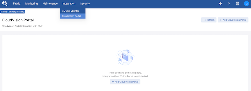
Navigate to Integration > CloudVision Portal.

Select Add CloudVision Portal to create a new CVP integration instance.

Figure 2. DMF Integration CloudVision Portal

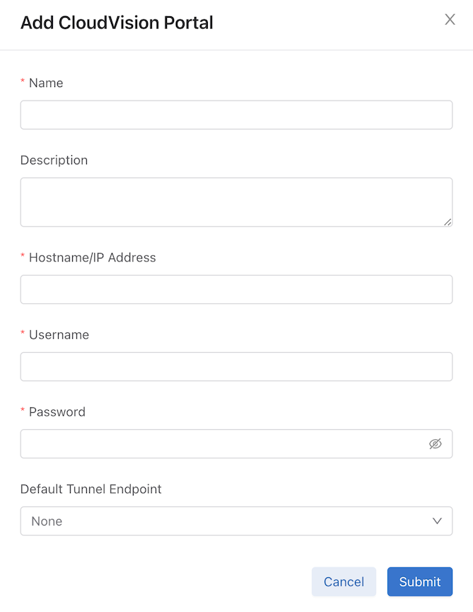
Enter the CVP integration instance configuration details and click Submit.

Figure 3. Add CloudVision Portal

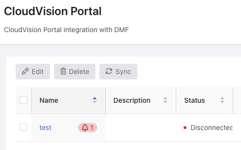
If there are any warnings or errors with the CVP integration instance, click the alarm bell icon to view more details.

Figure 4. CloudVision Portal
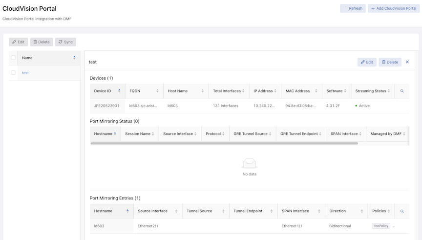
Select the CVP instance name to view its details, including the device inventory, port mirroring status, and port mirroring entries in DMF policies.
Note: The Port Mirroring Entries table will not be visible if no policies using this CVP instance as a traffic source have been configured.
Figure 5. CloudVision Portal Dashboard

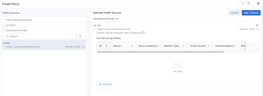
To start monitoring traffic from the production network:

  1. Navigate to Monitoring > Policies.

  2. Select Create Policy and add CVP instances as traffic sources.

  3. Select Add Row to configure monitoring, such as the device interfaces to monitor, the monitor type (e.g., SPAN or L2GRE), the mirrored traffic direction, and the destination.

Figure 6. Create DMF Policy

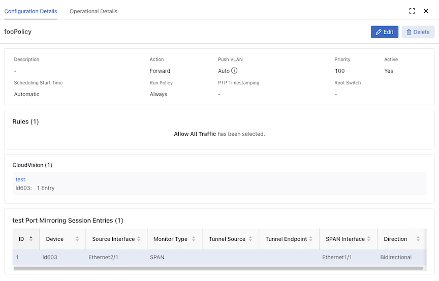
Policy configuration details related to CVP integration appear in the policy’s Configuration Details page.

Figure 7. Configuration Details

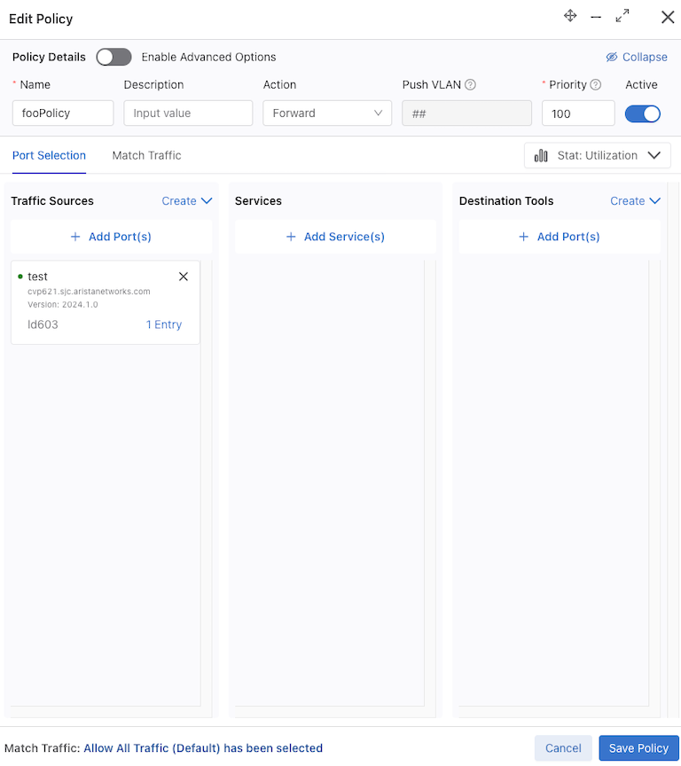
To edit the CVP monitoring configuration in a policy, click Edit and select 1 Entry on the Edit Policy page, make the required changes, and click Save Policy.

Figure 8. Edit Policy

Limitations

The following limitations apply to the DANZ Monitoring Fabric (DMF) Controller and CloudVision integration.

  • Modifying or deleting auto-generated filter interfaces for CVP integration or adding them manually to non-CloudVision policies will result in unexpected behavior.

  • If two or more DMF policies have overlapping CVP monitoring configurations with the same destination, the configuration should be the same in these policies if unexpected traffic is undesired. For example, if a policy has source interfaces A and B on a device in a CVP instance with a SPAN interface as the destination, and if another policy has one source interface, A, on the same device in the same CVP instance with the same SPAN interface as the former policy, then the latter policy will unexpectedly receive traffic from B as well as the expected source A. This is because the mirroring session in the production switch is reused for both policies.

  • An error state in the CVP deployment may prevent DMF from configuring mirroring sessions on the production switches. If DMF encounters such a failure, a fabric error will be displayed, and user action in CVP is required. Examples of such a state include the production switch not being in compliance in CVP, in which case it needs to be brought into compliance, or if there are any pending change controls in CVP, they must be addressed. After taking the appropriate corrective action in CVP, deactivate and reactivate the DMF policy with the error (or delete and recreate it) to retry configuring mirroring.

Troubleshooting

  • If there are any fabric errors in creating a mirroring session on a CVP-managed device that specify that user action in CVP is required, take the appropriate corrective action in CVP. Next, delete the CVP monitoring config from the policy and reconfigure it, or delete the policy and then recreate it.
  • If there is a message in the show cvp alert command output stating a session failed to be updated and an authentication error message in /var/log/vsphere-extension/vsphere-extension.log containing GNMI7001…Status unauthenticated, run the sync cvp command, and then deactivate and reactivate the relevant DMF policy.
  • If there is a fabric error containing No change controls to approve and execute, a possible cause is that the device had not been registered for use in Studios in CVP using the Inventory and Topology studio. If so, register the device in CVP and delete and recreate the DMF policy.

Telemetry Collector

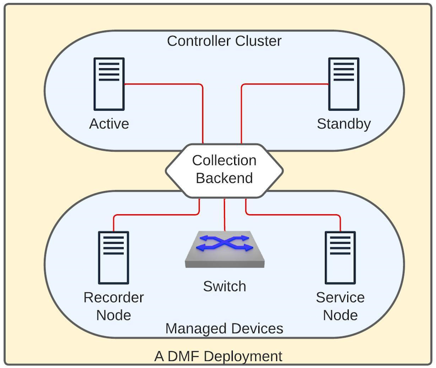
A DANZ Monitoring Fabric (DMF) consists of a pair of Controllers, switches, and managed appliances. The Telemetry Collector feature centrally retrieves the infrastructure metrics (interface counters, CPU usage, etc.) affiliated with all these devices from the controllers using its REST API.

Deployment

Figure 1. DMF Deployment

The diagram above shows a DMF deployment with an Active/Standby Controller cluster. In this environment, each Controller collects metrics from all the devices it manages and the controller nodes. Each Controller establishes a gNMI connection to all the devices and the other Controller in a fabric to collect telemetry streams. gNMI is a gRPC-based protocol to configure and access states on network devices. The REST API exposes this information in the /api/v1/data/controller/telemetry/data subtree. The Controller exposes several metrics about CPU, memory, disk utilization, interface counters, and sensor states of all devices in a fabric. All metrics are fetched at a 10-second frequency except those associated with the sensors, which are collected every minute.

Configuration

No additional configuration is necessary on the DMF Controller to enable the metric collection. However, to read these metrics, the user must be an admin user or configured with the privilege, category:TELEMETRY. To set the telemetry permission for a custom group and associate the user with this group, use the following commands:

dmf-controller(config)# group group_name
dmf-controller(config)# permission category:TELEMETRY privilege read-only
dmf-controller(config)# associate user username 

Connection Status

The Controller uses the gNMI protocol to collect telemetry data from all devices. DMF reports the status of these connections in both the REST API and the CLI.

REST API

The REST API subtree /api/v1/data/controller/telemetry/connection reports the telemetry connection state. The API Schema browser of the GUI provides more details.

CLI

The following show commands display the connection details. All these commands support filtering the output with a device name.

show telemetry connection device-name | all 
show telemetry connection device-name | all details
show telemetry connection device-name | all last-failure

The show telemetry connection device-name all command shows the state and the latest state change of the connection between the Controller and the devices.

dmf-controller# show telemetry connection all
# Name State Last state change
-|----------------------------|-----|------------------------------|
1 c2 ready 2023-11-10 13:10:02.718000 UTC
2 core2ready 2023-11-10 13:22:56.311000 UTC
<snip>

The show telemetry connection device-name all command displays the state and the latest state change of the connection between the Controller and the devices.

dmf-controller# show telemetry connection all details 
# NameState Last state changeTargetConnection type Last message time
-|-----|-----|------------------------------|-------------------|---------------|------------------------------|
1 core2 ready 2023-11-10 13:22:56.311000 UTC 10.243.255.102:6030 clear-text2023-11-10 13:59:35.437000 UTC
<snip>

The show telemetry connection device-nameall last-failure command displays more details about a connection failure. The time of the latest failure and the potential reason appear in the output. If the connection is still in the failed state, this output also shows when the next reconnection will be attempted.

dmf-controller# show telemetry connection all last-failure 
# NameFail timeFail type Root causeNext retry in 
-|-----|------------------------------|---------------|-------------------------|-------------|
1 core2 2023-11-10 13:19:34.237000 UTC unavailable UNAVAILABLE: io exception 0
<snip>

Limitations

  • Software interfaces (for example, loopback, bond, and management) do not report counters for broadcast and unicast packets.
  • The reported interface names are the raw physical interface name (e.g., et1) rather than the user-configured name associated with the role of an interface (e.g., filter1).
  • Resetting the interface counter does not affect the counter values stored at the /telemetry/data path. The value monotonically increases and corresponds to the total count since the device was last powered up. This value only gets reset when rebooting the device.

Usage Notes

  • DMF uses the configured name of a managed device (e.g., switch, recorder node, etc.) on the Controller as the value of the key name for the node device for all the metrics corresponding to it. In the case of a Controller, DMF uses the configured hostname as the key. Thus, these names must be unique in a specific DMF deployment.
  • The possibility exists that metrics are not collected from a device for a short period. This data gap may happen when rebooting the device or when the Controllers experience a failover event.
  • If the gNMI connection between the Controller and the device is interrupted, the Controller attempts a new connection after 2 minutes. The retry timeout for a subsequent connection attempt increases exponentially and can go up to 120 minutes. Upon a successful reconnection, this timeout value resets to 2 minutes.
  • There might be gNMI warning messages in the floodlight log during certain events, e.g., when first adding a device or it is reloading. Ignore these messages.
  • This feature enables an OpenConfig agent on switches running EOS to collect telemetry.

Telemetry Availability

As a DMF fabric consists of different types of devices, the metrics of each vary. The following outlines the metrics collected from each device type by the Controller and typically made available over its REST API. However, some specific platforms or hardware might not report a particular metric. For brevity, the following list mentions the leaves that can correspond to a metric. For more details, use the API Schema browser of the GUI.

telemetry
+-- data
 +-- device
 +-- interface
 |+-- oper-statusCtrl, SWL, EOS, SN, RN
 |+-- counters
 | +-- in-octets Ctrl, SWL, EOS, SN, RN
 | +-- in-pkts Ctrl, SWL, EOS, SN, RN
 | +-- in-unicast-pkts Ctrl, SWL, EOS, SN, RN
 | +-- in-broadcast-pkts Ctrl, SWL, EOS, SN, RN
 | +-- in-multicast-pkts Ctrl, SWL, EOS, SN, RN
 | +-- in-discards Ctrl, SWL, EOS, SN, RN
 | +-- in-errors Ctrl, SWL, EOS, SN, RN
 | +-- in-fcs-errors Ctrl, SWL, EOS, SN, RN
 | +-- out-octetsCtrl, SWL, EOS, SN, RN
 | +-- out-pktsCtrl, SWL, EOS, SN, RN
 | +-- out-unicast-pktsCtrl, SWL, EOS, SN, RN
 | +-- out-broadcast-pktsCtrl, SWL, EOS, SN, RN
 | +-- out-multicast-pktsCtrl, SWL, EOS, SN, RN
 | +-- out-discardsCtrl, SWL, EOS, SN, RN
 | +-- out-errorsCtrl, SWL, EOS, SN, RN
 +-- cpu
 |+-- utilizationCtrl, SWL, EOS, SN, RN
 +-- memory
 |+-- totalCtrl, SWL, SN, RN
 |+-- availableCtrl, SWL, EOS, SN, RN
 |+-- utilized Ctrl, SWL, EOS, SN, RN
 +-- sensor
 |+-- fan
 ||+-- oper-status Ctrl, SWL, EOS, SN, RN
 ||+-- rpm Ctrl, SWL, EOS, SN, RN
 ||+-- speed SWL
 |+-- power-supply
 ||+-- oper-status Ctrl, SWL, EOS, SN, RN
 ||+-- capacityEOS
 ||+-- input-current Ctrl, SWL, EOS, SN, RN
 ||+-- output-currentSWL, EOS
 ||+-- input-voltage Ctrl, SWL, EOS, SN, RN
 ||+-- output-voltageSWL, EOS
 ||+-- input-power Ctrl, SWL, SN, RN
 ||+-- output-powerSWL, EOS
 |+-- thermal
 | +-- oper-status Ctrl, SWL, SN, RN
 | +-- temperature Ctrl, SWL, EOS, SN, RN
 +-- mount-point
 |+-- size Ctrl, SWL, SN, RN
 |+-- availableCtrl, SWL, SN, RN
 |+-- utilized Ctrl, SWL, SN, RN
 |+-- usage-percentage Ctrl, SWL, SN, RN
 +-- control-group
 +-- memory Ctrl, SWL, SN, RN
 +-- cpuCtrl, SWL, SN, RN

* Ctrl = Controller, SWL = A switch running SwichLight OS, 
EOS = A switch running Arista EOS, SN = Service Node, RN = Recorder Node

DMF Controller in Microsoft Azure

The DANZ Monitoring Fabric (DMF) Controller in Azure feature supports the operation of the Arista Networks DMF Controller on the Microsoft Azure platform and uses the Azure CLI or the Azure portal to launch the Virtual Machine (VM) running the DMF Controller.

The DMF Controller in Azure feature enables the registration of VM deployments in Azure and supports auto-firstboot using Azure userData or customData.

Configuration

Configure Azure VMs auto-firstboot using customData or userData. There is no data merging from these sources, so provide the data via customData or userData, but not both.

Arista Networks recommends using customData as it provides a better security posture because it is available only during VM provisioning and requires sudo access to mount the virtual CDROM.

userData is less secure because it is available via Instance MetaData Service (IMDS) after provisioning and can be queried from the VM without any authorization restrictions.

If sshKey is configured for the admin account during Azure VM provisioning along with auto-firstboot parameters, then it is also configured for the admin user of DMF controllers.

The following table lists details of the firstboot parameters for the auto-firstboot configuration.

Firstboot Parameters - Required Parameters

Key Description Valid Values
admin_password This is the password to set for the admin user. When joining an existing cluster node this will be the admin-password for the existing cluster node. string
recovery_password This is the password to set for the recovery user. string

Additional Parameters

Key Description Required Valid Values Default Value
hostname This is the hostname to set for the appliance. no string Configured from Azure Instance Metadata Service
cluster_name This is the name to set for the cluster. no string Azure-DMF-Cluster
cluster_to_join This is the IP which firstboot will use to join an existing cluster. Omitting this parameter implies that the firstboot will create a new cluster.
Note: If this parameter is present ntp-servers, cluster-name, and cluster-description will be ignored. The existing cluster node will provide these values after joining.
no IP Address String  
cluster_description This is the description to set for the cluster. no string  

Networking Parameters

Key Description Required Valid Values Default Value
ip_stack What IP protocols to set up for the appliance management NIC. no enum: ipv4, ipv6, dual-stack ipv4
ipv4_method Setup IPv4 for the appliance management NIC. no enum: auto, manual auto
ipv4_address The static IPv4 address used for the appliance management NIC. only if ipv4-method is set to manual IPv4 Address String  
ipv4_prefix_length The prefix length for the IPv4 address subnet to use for the appliance management NIC. only if ipv4-method is set to manual 0..32  
ipv4_gateway The static IPv4 gateway to use for the appliance management NIC. no IPv4 Address String  
ipv6_method Set up IPv6 for the appliance management NIC. no enum: auto, manual auto
ipv6_address The static IPv6 address to use for the appliance management NIC. only if ipv6-method is set to manual IPv6 Address String  
ipv6_prefix_length The prefix length for the IPv6 address subnet to use for the appliance management NIC. only if ipv6-method is set to manual 0..128  
ipv6_gateway The static IPv6 gateway to use for the appliance management NIC. no IPv6 Address String  
dns_servers The DNS servers for the cluster to use no List of IP address strings  
dns_search_domains The DNS search domains for the cluster to use. no List of the host names or FQDN strings  
ntp_servers The NTP servers for the cluster to use. no List of the host names of FQDN strings

0.bigswitch.pool.ntp.org

1.bigswitch.pool.ntp.org

2.bigswitch.pool.ntp.org

3.bigswitch.pool.ntp.org

Examples

{
"admin_password": "admin_user_password",
"recovery_password": "recovery_user_password"
}

Full List of Parameters

{
"admin-password": "admin_user_password",
"recovery_password": "recovery_user_password",
"hostname": "hostname",
"cluster_name": "cluster name",
"cluster_description": "cluster description",
"ip_stack": "dual-stack",
"ipv4_method": "manual",
"ipv4_address": "10.0.0.3",
"ipv4_prefix-length": "24",
"ipv4_gateway": "10.0.0.1",
"ipv6_method": "manual",
"ipv6_address": "be:ee::1",
"ipv6_prefix-length": "64",
"ipv6_gateway": "be:ee::100",
"dns_servers": [
"10.0.0.101",
"10.0.0.102"
],
"dns_search_domains": [
"dns-search1.com",
"dns-search2.com"
],
"ntp_servers": [
"1.ntp.server.com",
"2.ntp.server.com"
]
}

Syslog Messages

  • There are three possible failure modes:
    • VM fails Azure registration.
    • auto-firstboot fails due to a transient error or bug.
    • auto-firstboot parameter validation fails.
  • These failures can be debugged by accessing the firstboot logs after manually booting the VM or logging via the recovery user on Azure serial console:
    • Azure DMF Controller VMs can be accessed via ssh login after successful firstboot:
      dmf-controller-0-vm> enable; configure;
      dmf-controller-0-vm> show logging syslog | grep 'floodlight-autofirstboot'
    • For debugging parameter validation errors, access the parameter validation results:
      dmf-controller-0-vm> show firstboot parameter-validation
  • Accessing logs via the recovery user on Azure serial console. The following output is an example log for missing a required firstboot parameter – admin_password:
    Log in as 'admin' to configure
    
    controller login: recovery
    recovery@controller:~$ cat /var/log/floodlight/firstboot/firstboot.log 
    ...
    2024-06-17 17:09:09,982 autofirstboot: CRITICAL [main] Uncaught exception
    Traceback (most recent call last):
    File "/usr/bin/floodlight-autofirstboot", line 11, in <module>
    load_entry_point('firstboot==0.1.0', 'console_scripts', 'floodlight-autofirstboot')()
    File "/usr/share/floodlight/firstboot/firstboot/autofirstboot.py", line 93, in main
    params, plugin = get_params(plugins)
    File "/usr/share/floodlight/firstboot/firstboot/autofirstboot.py", line 44, in get_params
    params = plugin.get_firstboot_params()
    File "/usr/share/floodlight/firstboot/firstboot/cloud_plugins/azure.py", line 75, in get_firstboot_params
    return FirstbootParams(**firstboot_param_dict)
    TypeError: __init__() missing 1 required positional argument: 'admin_password'

Troubleshooting

  • If a DMF Controller VM cannot be accessed via ssh login, the auto-firstboot has probably failed.
  • The DMF Controller VMs must be recreated on Azure for any transient failure for VM registration with Azure or for auto-firstboot to occur.
  • The DMF Controller VMs can also be configured manually for firstboot via the Azure serial console.

Limitations

The following limitations apply to the DANZ Monitoring Fabric (DMF) Controller in Microsoft Azure.

  • There is no support for any features specific to Azure-optimized Ubuntu Linux, including Accelerated Networking.
  • The DMF Controllers in Azure are only supported on Gen-1 VMs.
  • The DMF Controllers in Azure do not support adding the virtual IP address for the cluster.
  • There is no support for capture interfaces in Azure.
  • DMF ignores the Azure username and password fields.
  • There is no support for static IP address assignment that differs from what is configured on the Azure NIC.
  • The DMF Controllers are rebooted if the static IP on the NIC is updated.
  • Switches are supported in L3 ZTN mode only.

Resources

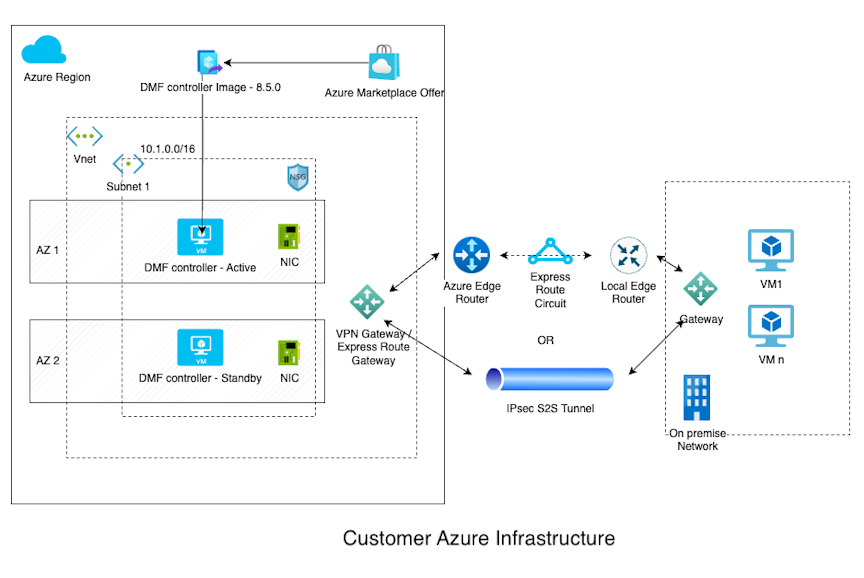
Diagrams

Figure 1. Customer Azure Infrastructure

Configuring Third-party Services

Services in the DANZ Monitoring Fabric

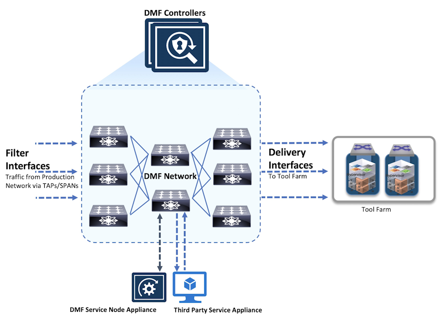
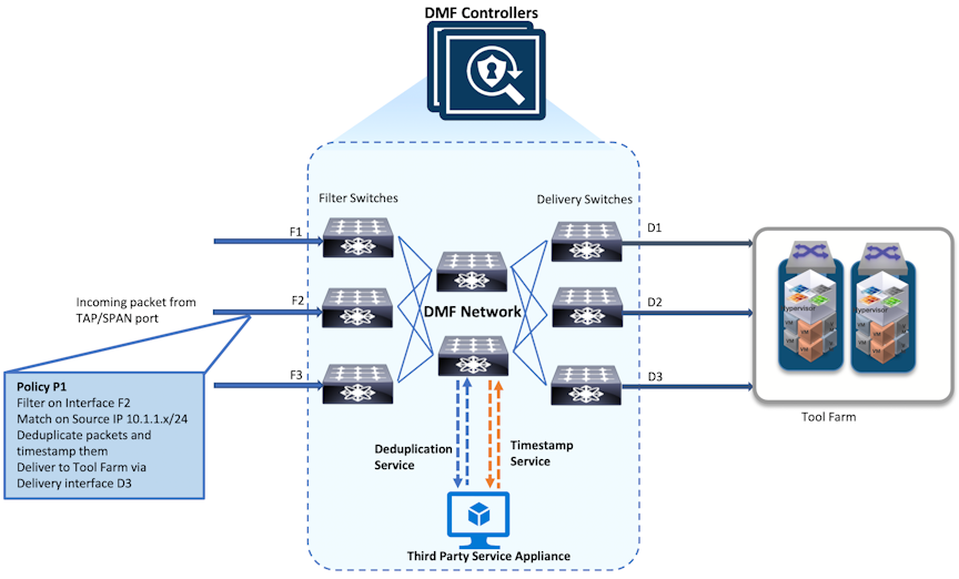
Services in the DANZ Monitoring Fabric (DMF) refer to packet modification operations provided by third-party network packet brokers (NPBs), referred to as service nodes. Services can include operations that refine or modify the data stream delivered to analysis tools.

Each service instance is assigned a numeric identifier because multiple services can be specified for a given policy. Services are applied sequentially, applying a service with a lower sequence number first.

Service nodes are optional devices that process interesting traffic before forwarding it to the delivery ports specified by the policy. Example services include time-stamping packets, packet slicing, or payload obfuscation. To configure a service node:

  • Create all the pre-service and post-service interfaces used with the service.
  • Use the DMF interface names to create a service node and add pre-service and post-service interfaces.
Figure 1. Using Services with a Policy
In the figure above, the time-stamping service is applied first, followed by the packet-slicing service. The illustration shows the CLI commands that associate the service with a specific policy. For the illustrated policy, the packet path is as follows:
  1. Filter interface (F3)
  2. Time-stamping service node (pre-service and post-service interfaces)
  3. (optional) Packet-slicing service node (pre-service and post-service interfaces)
  4. Delivery-interface (D2)

Once a policy includes a service, it is only optional if defined explicitly as optional. If not defined as optional in the policy, packet forwarding does not occur when the service is unavailable. For example, configuring the packet-slicing service as optional and a pre-service or post-service interface assigned to that service node is down, the service is skipped, and the packets are delivered to the D2 delivery interface after the time-stamping service is completed. However, if at least one pre-service and post-service interface is unavailable for the time-stamping service, this policy does not forward packets to the delivery interfaces.

Configure all the service interfaces before creating a service definition that uses them.
Note: Before defining a service, first create the service interface names. Otherwise, the service might enter an inconsistent state. If that happens, delete the service definition, create the interfaces, and then re-create the service definition. Alternatively, re-create the service definition without the nonexistent interfaces.
A DMF service can have multiple pre-service and post-service interfaces. Use a Link Access Group (LAG) as a pre-service or a post-service interface.
Note: Arista Networks strongly recommends configuring the post-service and pre-service interfaces on the same switch for any DMF service.

Using the GUI to Configure a DMF Unmanaged Service

To create a DANZ Monitoring Fabric (DMF) unmanaged service, perform the following steps:

  1. Select Monitoring > Services.
    The system displays the following table:
    Figure 2. DMF Unmanaged Service

    This table lists the services configured for the DMF. Add, delete, or modify existing services as required.

  2. To create a new service, click the provision control (+) in the table.
    The system displays the following dialog:
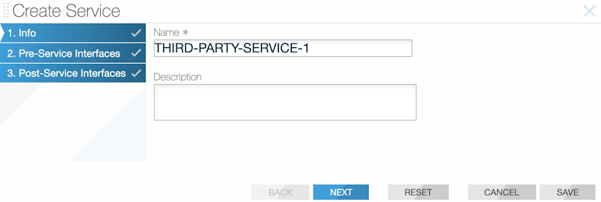
    Figure 3. Create Service Dialog: Info
  3. Type a unique name for the service and optional text description, then click Next.
    The system displays the following dialog:
    Figure 4. Create Service Dialog: Pre-service Interfaces

    This table lists the interfaces assigned as pre-service interfaces for the current service.

  4. To add a pre-service interface, click the provision control (+) in the table.
    The system displays the following dialog:
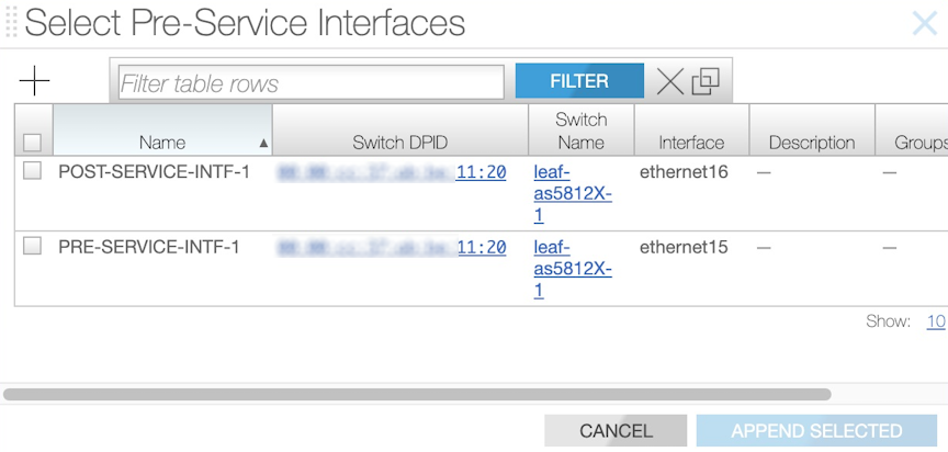
    Figure 5. Select Pre-service Interfaces

    This table lists the interfaces available for assignment as pre-service interfaces. To configure a new interface, click the provision control (+) in the table. The system displays a dialog for adding a service interface.

  5. Enable the checkbox for one or more interfaces to assign as a pre-service interface for the current service and click Append Selected.
  6. On page two of the Create Service Interface dialog, click Next.
    The system displays the following dialog:
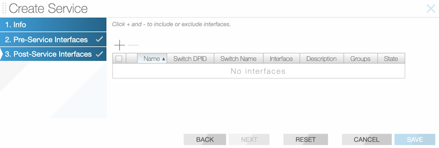
    Figure 6. Create Service Dialog: Post-service Interfaces

    This table lists the interfaces assigned as post-service interfaces for the current service.

  7. To add a post-service interface, click the provision control (+) in the table.
    The system displays the following dialog.
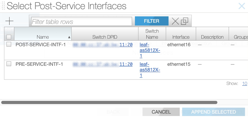
    Figure 7. Select Post-service Interfaces

    This table lists the interfaces available for assignment as post-service interfaces.

    To configure a new interface, click the provision control (+) in the table. The system displays a dialog for adding a service interface, as described in the Configuring DMF Unmanaged Services section.

  8. Enable the checkbox for one or more interfaces to assign as a post-service interface for the current service and click Append Selected.
  9. Click Save on page three of the Create Service Dialog.

Using the CLI to Configure a DMF Unmanaged Service

In the DANZ Monitoring Fabric (DMF), third-party tools that provide packet manipulation services, such as time stamping and packet slicing, are called DMF Unmanaged Services. These optional devices process traffic from filter interfaces before being forwarded to delivery interfaces.
Note: After adding a service to a policy, it is no longer optional unless specifically defining it as optional. If not defined as optional, the policy does not forward packets if the service is unavailable.

To configure an unmanaged service using the CLI, perform the following steps:

  1. Create one or more pre-service interfaces for delivering traffic to the NPB, as in the following example.
    controller-1(config-switch-if)# switch DMF-CORE-SWITCH
    controller-1(config-switch-if)# interface s9-eth1
    controller-1(config-switch-if)# role service interface-name pre-serv-intf-1
  2. Create one or more post-service interfaces for receiving traffic from the NPB, as in the following example:
    controller-1(config-switch-if)# interface s9-eth2
    controller-1(config-switch-if)# role service interface-name post-serv-intf-1
  3. Create a service node and add at least one pre-service and at least one post-service interface using the DMF interface names, as in the following example:
    controller-1(config)#controller-1(config)# unmanaged-service THIRD-PARTY-SERVICE-1
    controller-1(config-unmanaged-srv)# description "this is a third-party unmanaged service"
    controller-1(config-unmanaged-srv)# pre-service PRE-SERVICE-INTF-1
    controller-1(config-unmanaged-srv)# post-service POST-SERVICE-INTF-1
To list the configured services in the DMF fabric, enter the show unmanaged-services command, as in the following example:
controller-1# show unmanaged-service
~~~~~~~~~~~~~~~~~~~~~~~~~~~~~~~~~~~~~~~~~~~~~~~~~~~~~~~~~~~ Services ~~~~~~~~~~~~~~~~~~~~~~~~~~~~~~~~~~~~~~~~~~~~~~~~~~~~~~~~~~~
# Service NameMax from service bandwidth bps Max to service bandwidth bps Total from service bps Total to service bps
-|---------------------|------------------------------|----------------------------|----------------------|--------------------|
1 THIRD-PARTY-SERVICE-1 10Gbps 10Gbps --
~~~~~~~ Post-groups of Service Names ~~~~~~~
# Service NameDmf name
-|---------------------|-------------------|
1 THIRD-PARTY-SERVICE-1 POST-SERVICE-INTF-1
~~~~~~~ Pre-groups of Service Names ~~~~~~~
# Service NameDmf name
-|---------------------|------------------|
1 THIRD-PARTY-SERVICE-1 PRE-SERVICE-INTF-1
To display information about a service, specify the service name, as in the following example:
controller-1 # show unmanaged-service THIRD-PARTY-SERVICE-1
~~~~~~~~~~~~~~~~~~~~~~~~~~~~~~~~~~~~~~~~~~~~~~~~~~~~~~~~~~~ Services ~~~~~~~~~~~~~~~~~~~~~~~~~~~~~~~~~~~~~~~~~~~~~~~~~~~~~~~~~~~
# Service NameMax from service bandwidth bps Max to service bandwidth bps Total from service bps Total to service bps
-|---------------------|------------------------------|----------------------------|----------------------|--------------------|
1 THIRD-PARTY-SERVICE-1 10Gbps 10Gbps --
~~~~~~~ Post-groups of Service Names ~~~~~~~
# Service NameDmf name
-|---------------------|-------------------|
1 THIRD-PARTY-SERVICE-1 POST-SERVICE-INTF-1
~~~~~~~ Pre-groups of Service Names ~~~~~~~
# Service Name SERVICE-1 PRE-SERVICE-INTF-1

Service Insertion and Chaining in a DMF Policy

To configure a DANZ Monitoring Fabric (DMF) policy that uses services provided by an NPB, add the use-service command to the policy. Services can be configured in series, called chaining, as shown below:
Figure 8. Service Insertion and Chaining

Because a given policy can specify multiple services, set a sequence number for each service instance so the services are applied in order for the policy traffic. A lower sequence number applies the service first.

To configure a DMF out-of-band policy that uses services provided by an NPB, use the use-service command from the config-policy submode to add the service to the policy.

The following are the configuration commands for implementing the illustrated example:
controller-1(config)# policy DMF-POLICY-1
controller-1(config-policy)# use-service UMS-DEDUPLICATE-1 sequence 100
controller-1(config-policy)# use-service UMS-TIMESTAMP-1 sequence 101
In this example, the packet deduplication service is applied first, followed by time stamping. If all the pre-service or post-service interfaces for the packet-slicing service nodes are down, then this service is skipped if configured as optional. In this example, the time-stamping service is applied before the packet deduplication service, and the packet deduplication service is configured as optional.
controller-1(config)# policy DMF-POLICY-1
controller-1(config-policy)# use-service UMS-TIMESTAMP-1 sequence 100
controller-1(config-policy)# use-service UMS-DEDUPLICATE-1 sequence 101 optional
.. note::
If a service is inserted, the policy can only become active and begin forwarding when at
least one delivery port is reachable from all the post-service interfaces defined for the service.

Enter the show policy command from any mode to display the run time services being applied.

DMF Recorder Node REST API

The REST server is available over HTTPS on the default port (443) using either of the two authentication methods supported:
  • HTTP basic: The client presents a valid username and password for the Controller connected with the Recorder. The DANZ Monitoring Fabric (DMF) Recorder Node verifies at the DMF Controller if the provided username and password are valid and have sufficient privileges to use the Recorder REST API.
  • Authentication tokens: The DMF Recorder Node REST API accepts revocable authentication tokens as an alternative to HTTP basic. Valid authentication tokens are configured in the Controller and pushed down to the DMF Recorder Node using a gentable. Any client with a valid authentication token can query the DMF Recorder Node REST API without real-time consultation with the Controller.

Some APIs accept a Stenographer query string as input or return a Stenographer query string as output. A Stenographer query string is a BPF-like syntax for defining the scope of a query. Packets that match this scope are included in the query result or operation. For details about the Stenographer query syntax supported by the DMF Recorder Node, refer to the Stenographer Reference for DMF Recorder Node. The DMF Recorder Node provides a REST API so clients can look up packets and metadata. The REST server runs securely (HTTPS) on TCP port 443.

Authentication

Clients must either authenticate using a valid DANZ Monitoring Fabric (DMF) Controller username and password over HTTP Basic or with an authentication token configured on the DMF controller specifically for DMF Recorder Node REST API authentication.

Basic HTTP Authentication

Use a valid DANZ Monitoring Fabric (DMF) Controller username and password to authenticate with a DMF Recorder Node over its REST API. The recorder node delegates authentication to the DMF Controller. If the username and password provided are valid, the recorder node authorizes the user for the invoked recorder node REST endpoint.

In the following example, the query uses the HTTP Basic method of authentication:
$ curl https://1.2.3.4/query/window -u admin:12345 -k | python -m json.tool
% Total % Received % Xferd Average Speed Time Time Time Current
Dload Upload Total Spent Left Speed
100 79 100 79 0 0 143 0 --:--:-- --:--:-- --:--:-- 143
{
"begin": "2019-01-23 15:15:23 +0000 UTC",
"end": "2019-02-04 17:39:52 +0000 UTC"
}

In this example, the recorder node IP address is 1.2.3.4. The username on the DMF Controller is admin, and the password is 12345.

Authentication with an Authentication Token

An authentication token is primarily designed for third-party applications and automation scripts where creating an account or storing a username and password is undesirable. This method can also allow a DANZ Monitoring Fabric (DMF) Recorder Node access if the management network connection to the Controller is disrupted.

To create an authentication token, log in to the DMF Controller associated with the recorder node, then perform the following steps:

  1. Change to config mode on the active DMF Controller.
    controller-1# configure
    controller-1(config)#
  2. Define the authentication token using a unique name.
    controller-1(config)# recorder-node auth token my-token
    Auth : my-token
    Token : the-secret-token
    Note: This name does not need to be secret. This example uses the name my-token.
The Controller generates a secret token (in this example, the-secret-token). Treat this token as private. Anyone who presents it to the DMF Recorder Node can use the DMF Recorder Node REST APIs.
Note: Only the non-reversible hash of this token is stored on the DMF Recorder Node and Controller. There is no way to recover the token if it is lost. (See below for how to revoke the token if it is lost or compromised.)
The Controller stores the token hash and the name assigned, viewable by entering the show running-config recorder-node command, as in the following example:
controller-1(config)# show running-config recorder-node auth token
! recorder-node
recorder-node auth token my-token $2a$12$pXm62tl5rMD8c4vSrzU6X.DTjeoBmRUwZvTkvNXatsZ8TFb4PxanC
If the token is lost or compromised, remove it from the Controller, and the Controller will fail any attempt to authenticate to the recorder using the token.
controller-1(config)# no recorder-node auth token my-token
controller-1(config)# show running-config recorder-node auth token
controller-1(config)#
The following example illustrates a query using the authentication token method. The authentication token is defined in the HTTP request as the value of the cookie header.
$ curl https://1.2.3.4/query/inventory/window --header "Cookie:plaintext-secret-auth-token" -k |
python
-m json.tool
% Total % Received % Xferd Average Speed Time Time Time Current
Dload Upload Total Spent Left Speed
100 79 100 79 0 0 83 0 --:--:-- --:--:-- --:--:-- 83
{
"begin": "2019-01-23 15:15:23 +0000 UTC",
"end": "2019-02-04 17:50:46 +0000 UTC"
}

In this example, the DMF Recorder Node IP address is 1.2.3.4. The authentication token has already been generated on the DMF controller associated with the recorder node and is included in the cookie header as plaintext-secret-auth-token.

Only include the plaintext authentication token, not the token hash, saved in the controller running configuration. If the plaintext token is unknown, revoke access for the token and generate a new one. Note the plaintext value displayed after generating the new token.

DMF Recorder Node API Headers

The supported REST API HTTP header entries are listed in the following table.

Table 1. DANZ Monitoring Fabric (DMF) Recorder Node REST API HTTP Headers
Header Value Type Description
Steno-Limit-Bytes:value integer max number of bytes to accept in a packet query response
Steno-Limit-Packets:value integer max number of packets to accept in a packet query response
Cookie:value string auth token to use in lieu of HTTP basic auth

DMF Recorder Node REST APIs

The supported DANZ Monitoring Fabric (DMF) Recorder Node REST APIs are listed below.

Ready

/ready

  • Description: Is the DANZ Monitoring Fabric (DMF) Recorder Node able to accept queries? Return payload indicates progress towards start up completion.
  • HTTP Method: GET
  • Request Payload:
  • Return MIME Type:
  • Return Payload:
    {
    "current-value": <int>,
    "max-value": <int>,
    "percent-complete": <float>
    }
  • Return Status Code:
    • 200, ready
    • 503, not ready

Query Window

/query/window

  • Description: Get timestamp of oldest and newest packet available for query.
  • HTTP Method: GET
  • Request Payload:
  • Return MIME Type: application/json
  • Return Payload:
    {
    "begin" : <RFC-3339>,
    "end" : <RFC-3339>
    }
  • Return Status Code:
    • 200, success
    • 400, input error
    • 500, internal error
    • 503, not ready

Query Size

/query/size

  • Description: Get count and aggregate size of packets matching provided filter.
  • HTTP Method: POST
  • Request Payload: Stenographer query string
  • Return MIME Type: application/json
  • Return Payload:
    {
    "packet-count" : <int>,
    "aggregate-size" : <int>
    }
  • Return Status Code:
    • 200, success 400, input error
    • 500, internal error
    • 503, not ready

Query Application

/query/application

  • Description: Perform DPI on packets matching provided filter. DPI is performed using nDPI.
  • HTTP Method: POST
  • Request Payload: Stenographer query string
  • Return MIME Type: application/json
  • Return Payload: Defined by nDPI
  • Return Status Code:
    • 200, success
    • 400, input error
    • 500, internal error
    • 503, not ready

Query Packet

/query/packet

  • Description: Download pcap of packets matching provided filter.
  • HTTP Method: POST
  • Request Payload: Stenographer query string
  • Return MIME Type: application/vnd.tcpdump.pcap
  • Return Payload: .pcap file
  • Return Status Code:
    • 200, success
    • 400, input error
    • 500, internal error
    • 503, not ready

Query Analysis Filter Stenographer Analysis Type

/query/analysis[filter="<stenographer-query-string>"][type ="<analysis-type>"]

  • Description: Perform an analysis on the packets matching the stenographer query string. Supported values for analysis-type are:
    • analysis_http_tree
    • analysis_http_stat
    • analysis_http_req_tree
    • analysis_http_srv_tree
    • analysis_dns_tree
    • analysis_hosts
    • analysis_conv_ipv4
    • analysis_conv_ipv6
    • analysis_conv_tcp
    • analysis_conv_udp
    • analysis_rtp_streams
    • analysis_sip_stat
    • analysis_conv_sip
    • analysis_tcp_packets
    • analysis_tcp_flow_health
  • HTTP Method: GET
  • Request Payload:
  • Return MIME Type: application/json
  • Return Payload: Determined by the analysis type selected.
  • Return Status Code:
    • 200, success
    • 400, input error
    • 500, internal error
    • 503, not ready

Query Replay Request Stenographer Real-time Boolean

/query/replay/request[filter="<stenographer-query-string>"][real-time="<boolean>"]

  • Description: Asynchronously request packets matching filter be replayed into the monitoring fabric. Replay is performed using tcp replay.
  • HTTP Method: POST
  • Request Payload:
  • Return MIME Type: application/json
  • Return Payload:
    {
    "id" : <int>,
    "message": <string>
    }
  • Return Status Code:
    • 200, success
    • 400, input error
    • 500, internal error
    • 503, not ready

Query Replay Request Filter Stenographer Integer

/query/replay/request[filter="<stenographer-query-string>"][speed-mbps="<int>"]

  • Description: Asynchronously request packets matching filter be replayed into the monitoring fabric. Replay is performed using tcp replay.
  • HTTP Method: POST
  • Request Payload:
  • Return MIME Type: application/json
  • Return Payload:
    {
    "id" : <int>,
    "message": <string>
    }
  • Return Status Code:
    • 200, success
    • 400, input error
    • 500, internal error
    • 503, not ready

Query Replay Done

/query/replay/done

  • Description: Check the status of a replay matching the provided ID. Message contains replay result from tcp replay.
  • HTTP Method: POST
  • Request Payload: Replay ID
  • Return MIME Type: application/json
  • Return Payload:
    {
    "id" : <int>,
    "done" : <boolean>,
    "message": <string>
    }
  • Return Status Code:
    • 200, success
    • 400, input error
    • 404, replay ID unknown
    • 406, replay not done
    • 500, internal error
    • 503, not ready

Erase Packet Filter Stenographer Query String

/erase/packet[filter="<stenographer-query-string>"]

  • Description: Erase packets matching the provided filter. Note that any packet not matching the filter but in the same packet file of a packet matching the filter will also be deleted.
  • HTTP Method: POST
  • Request Payload:
  • Return MIME Type: application/json
  • Return Payload:
    {
    "bytes-erased" : <int>,
    "message" : <string>
    }
  • Return Status Code:
    • 200, success
    • 400, input error
    • 500, internal error
    • 503, not ready

Event Update Trigger Boolean Name Integer

/event/update[trigger="<boolean>"][name="<string>"][pre-buffer-minutes="<int>"]

  • Description: Trigger or terminate the named event. Set pre-buffer-minutes to 0 to use the available pre-buffer.
  • HTTP Method: POST
  • Request Payload:
  • Return MIME Type: application/json
  • Return Payload:
    {
    "message" : <string>,
    "event-queued" : <boolean>
    }
  • Return Status Code:
    • 200, success
    • 400, input error
    • 500, internal error
    • 503, not ready

Abort Query

/abort/query

  • Description: Terminate a particular query defined by the provided Stenographer query string.
  • HTTP Method: POST
  • Request Payload:
  • Return MIME Type: application/json
  • Return Payload:
    {
    "message" : <string>
    }
  • Return Status Code:
    • 200, success
    • 400, input error
    • 500, internal error
    • 503, not ready

Abort All Query

/abort-all/query

  • Description: Terminate all running queries.
  • HTTP Method: POST
  • Request Payload:
  • Return MIME Type: application/json
  • Return Payload:
    {
    "message" : <string>
    }
  • Return Status Code:
    • 200, success
    • 400, input error
    • 500, internal error
    • 503, not ready

Queries

/queries

  • Description: Determine the currently running queries, enumerated by the Stenographer query string of the query.
  • HTTP Method: GET
  • Request Payload:
  • Return MIME Type: application/json
  • Return Payload:
    {
    "queries" : [
    <stenographer-query-string>, ...
    ]
    }
  • Return Status Code:
    • 200, success
    • 400, input error
    • 500, internal error
    • 503, not ready

Status Query

/status/query

  • Description: Determine how far a given query has progressed. This can be used to estimate the time remaining to run the query.
  • HTTP Method: GET
  • Request Payload:
  • Return MIME Type: application/json
  • Return Payload:
    {
    "query" : <stenographer-query-string>, "current-value" : <int>,
    "max-value" : <int>, "percent-complete" : <float>
    }
  • Return Status Code:
    • 200, success
    • 400, input error
    • 500, internal error
    • 503, not ready

Status All

/status/all

  • Description: Determine how far all queries have progressed. This can be used to estimate the time remaining to run the queries.
  • HTTP Method: GET
  • Request Payload:
  • Return MIME Type: application/json
  • Return Payload:
    {
    "queries" : [
    {
    "query" : <stenographer-query-string>,
    "current-value" : <int>,
    "max-value" : <int>,
    "percent-complete" : <float>
    },
    ...
    ]
    }
    • Return Status Code:
      • 200, success
      • 400, input error
      • 500, internal error
      • 503, not ready

Stenographer Reference for DMF Recorder Node

This appendix provides information about composing Stenographer queries and submitting them through REST API.

Stenographer Query Syntax

The DANZ Monitoring Fabric (DMF) Recorder Node accepts Stenographer queries using a syntax based on the Berkeley Packet Filter (BPF) syntax. When entering a malformed BPF string, the recorder node will respond with an error. The entire BPF grammar is not supported, but query strings can be composed using the predicates in the following table.

Table 1. Table 1: Supported Stenographer BPF Query Strings
BPF Predicate Value Description
before value time string before the specified time
before value m ago duration before value minutes ago
before value h ago duration before value hours ago
before value d ago duration before value days ago
before value w ago duration before value weeks ago
after value time string after the specified time
after value m ago duration after value minutes ago
after value h ago duration after value hours ago
vlan value VLAN ID match the specified VLAN tag (outer, inner, or inner inner)
outer vlan value VLAN ID match the specified outer VLAN tag
inner vlan value VLAN ID match the specified inner VLAN tag (or middle tag of triple-tagged packets)
inner vlan value VLAN ID match the specified innermost VLAN tag of triple-tagged packets
src mac value MAC address match the specified MAC address in typical colon-delimited form (e.g. 11:22:33:44:55)
dst mac value MAC address match the specified MAC address in typical colon-delimited form (e.g. 11:22:33:44:55)
mpls value MPLS label match the specified MPLS label
src host value IPv4/v6 address match the specified source address exactly
dst host value IPv4/v6 address match the specified destination address exactly
src net value IPv4/v6 address match the specified source address with an optional CIDR mask. All octets of address must be specified, e.g. good → 1.2.3.0/24, bad → 1.2.3/24
src net value mask value IPv4/v6 address match the specified source address with masked with the specified address
dst net value IPv4/v6 address match the specified destination address with an optional CIDR mask. All octets of address must be specified, e.g. good → 1.2.3.0/24, bad → 1.2.3/24
dst net value mask value IPv4/v6 address match the specified destination address with masked with the specified address
ip proto value protocol number match the specified IP protocol number
icmp   match ICMP packets (shortcut for “ip proto 1”)
tcp   match TCP packets (shortcut for “ip proto 6”)
udp   match UDP packets (shortcut for “ip proto 17”)
src port value transport port number match the specified transport port number
dst port value transport port number match the specified transport port number
cid value Community ID match the provided community ID in standard version:base-64 encoded form (e.g. 1:hO+sN4H+MG5MY/8hIrXPqc4ZQz0=)
policy value DMF policy name match the forwarding VLAN(s) of the specified DMF policy. Only supported through the DMF Controller. Not supported when using a Recorder Node REST API directly.
filter-interface value DMF filter interface name match the forwarding VLAN of the specified filter interface. Only supported through the DMF Controller. Not supported when using a Recorder Node REST API directly.
event value Recorder Node event name match the time range of the specified event. Only supported through the DMF Controller. Not sup- ported when using a Recorder Node REST API directly.
and   logical “and”
&&   logical “and”
or   logical “or”
||   logical “or”
(   begin grouping
)   end grouping

Example Stenographer Queries

Note:Arista Networks recommends always using a specific time range in each query.

After two hours ago but before one hour ago, search for all packets to or from Google DNS (8.8.8.8).

(after 2h ago and before 1h ago) and (src host 8.8.8.8 or dst host 8.8.8.8)
In the last twenty-four hours, search for all SSH (TCP port 22) packets destined for IP 10.4.100.200.
Note: This will not match any SSH packets from 10.4.100.200.
after 24h ago and dst host 10.4.100.200 and tcp and src port 22

Within the last five minutes, search for all packets to or from 10.1.1.100. And, in the five minutes before that, search for all packets to or from 10.1.100.101.

(after 5m ago and (src host 10.1.1.100 or dst host 10.1.1.100)) or (after 10m ago and before 5m ago
and (src host 10.1.1.101 or dst host 10.1.1.101))

Within the timespan of event abc and within the last hour, search for all SSH (TCP port 22) packets destined for IP 1.2.3.4.

(event abc or after 1h ago) and dst host 1.2.3.4 and tcp and dst port 22

Within the timespan defined by the intersection of events abc and def, search for all packets sent from any IP in subnet 1.2.3.0/24 seen on filter interface xyz.

(event abc and event def) and filter-interface xyz and src net 1.2.3.0/24
.. note::
To use the filter-interface predicate, the DMF Controller must be in the push-per-filter Auto
VLAN mode.

Within the last five minutes, search for all packets sent from IP 1.2.3.4 to the DANZ Monitoring Fabric (DMF) Recorder Node using DMF policy abc.

after 5m ago and policy abc and src host 1.2.3.4
.. note::
To use the policy predicate the DMF Controller must be in the push-per-policy or push-per-
filter Auto VLAN mode. When in push-per-policy auto-vlan-mode, the policy's forwarding tag will
be queried. When in push-per-filter mode, the forwarding tags of the filter interfaces used in
the policy are queried.

Within the last five minutes, search for all packets with any VLAN tag 100.

after 5m ago and vlan 100

Within the last five minutes, search for all packets with an outer VLAN tag 100.

after 5m ago and outer vlan 100

Within the last five minutes, search for all packets with an inner (or middle) VLAN tag 100.

after 5m ago and inner vlan 100

Within the last five minutes, search for all triple-tagged packets with innermost VLAN tag 100.

after 5m ago and inner inner vlan 100

Within the last five minutes, search for packets belonging to a flow with community ID of 1:hO+sN4H+MG5MY/8hIrXPqc4ZQz0=.

after 5m ago and cid 1:hO+sN4H+MG5MY/8hIrXPqc4ZQz0=

This matches packets in each direction of the flow, if applicable.

Within the last five minutes, search for all L2 broadcast packets originating from MAC address 11:22:33:44:55:66.

after 5m ago and src mac 11:22:33:44:55:66 and dst mac ff:ff:ff:ff:ff:ff

Advanced Policy Configuration

This chapter describes advanced features and use cases for DANZ Monitoring Fabric (DMF) policies.

Advanced Match Rules

Optional parameters of a match rule (such as src-ip, dst-ip, src-port, dst-port) must be listed in a specific order. To determine the permitted order for optional keywords, use the tab key to display completion options. Keywords in a match rule not entered in the correct order results in the following message:
Error: Unexpected additional arguments ...

Match Fields and Criteria

The following summarizes the different match criteria available:

  • src-ip, dst-ip, src-mac, and dst-mac are maskable. If the mask for src-ip, dst-ip, src-mac, or dst-mac is not specified, it is assumed to be an exact match.
  • For src-ip and dst-ip, specify the mask in either CIDR notation (for example, /24) or dotted-decimal notation (255.255.255.0).
  • For src-ip and dst-ip, the mask must be contiguous. For example, a mask of 255.0.0.255 or 0.0.255.255 is not supported.
  • For TCP, the tcp-flags option allows a match on the following TCP flags: URG, ACK, PSH, RST, SYN, and FIN.
The following match combinations are not allowed in the same match rule in the same DMF policy.
  • src-ip-range and dst-ip-range
  • src-ip address group and dst-ip address group
  • ip-range and ip address group

DANZ Monitoring Fabric (DMF) supports matching on user-defined L3/L4 offsets instead of matching on these criteria. However, it is not possible to use both matching packet methods in the same DMF. Switching between these match modes may cause policies defined under the previous mode to fail.

Apply match rules to the following fields in the packet header:

dscp-value Match on DSCP value. Value range is 0..63
dst-ip Match dst ip
dst-port Match dst port
is-fragment Match if the packet is IP fragmented
is-not-fragment Match if the packet is not IP fragmented
l3-offset Match on l3 offset
l4-offset Match on l4 offset
range-dst-ip Match dst-ip range
range-dst-port Match dst port ramge
range-src-ip Match src-ip range
range-src-port Match src port range
src-ip Match src ip
src-port Match src port
untagged Untagged (no vlan tag)
vlan-id Match vlan-id
vlan-id-range Match vlan-id range
<ip-proto> IP Protocol
Warning: Matching on untagged packets cannot be applied to DMF policies when in push-per-policy mode.
DMF uses a logical AND if a policy match rule has multiple fields. For example, the following rule matches if the packet has src-ip 1.1.1.1 AND dst-ip 2.2.2.2:
1 match ip src-ip 1.1.1.1 255.255.255.255 dst-ip 2.2.2.2 255.255.255.255
DMF uses a logical OR when configuring two different match rules. For example, the following matches if the packet has src-ip 1.1.1.1 OR dst-ip 2.2.2.2:
1 match ip src-ip 1.1.1.1 255.255.255.255
2 match ip dst-ip 2.2.2.2 255.255.255.255
A match rule with the any keyword matches all traffic entering the filter interfaces in a policy:
controller-1(config)# policy dmf-policy-1
controller-1(config-policy)# 10 match any
The following commands match on the TCP SYN and SYN ACK flags:
1 match tcp tcp-flags 2 2
2 match tcp tcp-flags 18 18
Note: In the DMF GUI, when configuring a match on TCP flags, the current GUI workflow also sets the hex value of the TCP flags for the mask attribute. When configuring a different value for the tcp-flags and tcp-flags-mask attributes in a rule via the DMF CLI, editing the rule in the GUI will override the tcp-flags-mask.

Match-except Rules

The following summarizes match-except rules with examples which allow a policy to permit packets that meet the match criteria, except packets that match the value specified using the except command.
  • Match-except only supports IPv4 source-IP and IPv4 destination-IP match fields.
    • Example - Permit src-ip network, except ip-address:
      1 match ip src-ip 172.16.0.0/16 except-src-ip 172.16.0.1 
    • Example - Permit dst-ip network, except subnet
      1 match ip dst-ip 172.16.0.0/16 except-dst-ip 172.16.128.0/17
  • In a rule, the except condition can only be used with either src-ip or dst-ip, but not with src-ip and dst-ip together.
    • Example - Except being used with src-ip:
      1 match icmp src-ip 172.16.0.0/16 except-src-ip 172.16.0.1 dst-ip 172.16.0.0/16
    • Example - Except being used with dst-ip:
      1 match icmp src-ip 224.248.0.0/24 dst-ip 172.16.0.0/16 except-dst-ip 172.16.0.0/18
  • Except-src-ip or except-dst-ip can only be used after a match for src-ip or dst-ip, respectively.
    • Example - Incorrect match rule:
      1 match icmp except-src-ip 192.168.1.10 
    • Example - Correct match rule:
      1 match icmp src-ip 192.168.1.0/24 except-src-ip 192.168.1.10
  • In a match rule, only one IP address, or one subnet (range of IP addresses) can be used with the except command.
    • Example - Deny a subnet:
      1 match ip dst-ip 172.16.0.0/16 except-dst-ip 172.16.0.0/18
    • Example - Deny an IP Address:
      1 match ip dst-ip 172.16.0.0/16 except-dst-ip 172.16.0.1

Matching with IPv6 Addresses

The value of the EtherType field determines whether the src-ip field to match is IPv4 or IPv6. The DANZ Monitoring Fabric (DMF) Controller displays an error if there is a mismatch between the EtherType and the IP address format.

DMF supports IPv6 address/mask matching, either on src-IP or dst-IP. Optionally, UDP/TCP ports can be used with the IPv6 address/mask match. Specify an address/mask or a group; DMF does not support ranges for IPv6 addresses.
Note: Match rules containing both MAC addresses and IPv6 addresses are not accepted and cause a validation error.
  • The preferred IPv6 address representation is as follows: xxxx:xxxx:xxxx:xxxx:xxxx:xxxx:xxxx:xxxx, where each x is a hexadecimal digit representing 4 bits.
  • IPv6 addresses range from 0000:0000:0000:0000:0000:0000:0000:0000 to ffff:ffff:ffff:ffff:ffff:ffff:ffff.
    In addition to this preferred format, IPv6 addresses may be specified in two other shortened formats:
    • Omit Leading Zeros: Specify IPv6 addresses by omitting leading zeros. For example, write IPv6 address 1050:0000:0000:0000:0005:0600:300c:326b as 1050:0:0:0:5:600:300c:326b.
    • Double Colon: Specify IPv6 addresses using double colons (::) instead of a series of zeros. For example, write IPv6 address ff06:0:0:0:0:0:0:c3 as ff06::c3. Double colons may be used only once in an IP address.

DMF does not support the IPv4 address embedded in the IPv6 address format. For example, neither 0:0:0:0:0:0:101.45.75.219 nor ::101.45.75.219 can be used.

Both IPv4 and IPv6 masks must be in CIDR format. For example, FFFF:FFFF:FFFF:FFFF:0:0:0:0 is valid in DMF, but FFFF:0:0:FFFF:FFFF:0:0:0:0 is not a valid mask.

Both the colon-separated hexadecimal representation and the CIDR-style mask format are supported. The following example illustrates the correct format for IPv6 addresses and subnet masks:
controller-1(config)# policy dmf-ipv6-policy
controller-1(config-policy)# 10 match ip6 src-ip 2001::0 ffff:ffff:ffff:ffff:0:0:0:0
controller-1(config-policy)# 11 match ip6 dst-ip 2001:db8:122:344::/64
controller-1(config-policy)# filter-interface all
controller-1(config-policy)# action drop

Port and VLAN Range Matches

DANZ Monitoring Fabric (DMF) policy supports matching on source and destination port ranges with optimized hardware resource utilization. DMF uses efficient masking algorithms to minimize the number of flow entries in hardware for each VLAN range. For example, a VLAN range of 12-99 uses only five flows in hardware.
Note: Use the untagged keyword to match traffic without a VLAN tag.
Provide the IP protocol information when using source and destination port ranges, fully supported for IPv4 and IPv6 for TCP and UDP. These keywords have the following options:
  • range-dst-ip: Match dst-ip range.
  • range-dst-port: Match dst port range.
  • range-src-ip: Match src-ip range.
  • range-src-port: Match src port range.
Specify either src-port-range or dst-port-range or both in each match rule, as illustrated in the following example:
controller-1(config)# policy ip-port-range-policy
controller-1(config-policy)# 10 match tcp range-src-port 10 100
controller-1(config-policy)# 15 match udp range-dst-port 300 400
controller-1(config-policy)# 20 match tcp range-src-port 10 2000 range-dst-port 400 800
controller-1(config-policy)# 30 match tcp6 range-src-port 8 20
controller-1(config-policy)# 40 match tcp6 range-src-ip 1:2:3:4::/64 range-src-port 10 300
controller-1(config-policy)# filter-interface all
controller-1(config-policy)# delivery-interface all
controller-1(config-policy)# action forward
DMF policy supports matches for the VLAN ID range with optimized hardware resource utilization. Combining a VLAN ID range with a source or destination port range is supported, but not using all three ranges in a single match. The following example illustrates a valid use of the VLAN ID range option:
controller-1(config)# policy vlan-range-policy
controller-1(config-policy)# 10 match mac vlan-id-range 30 400
controller-1(config-policy)# 20 match full ether-type ip protocol 6 vlan-id-range 1000 3000 srcip 1.
1.1.1 255.255.255.255 src-port-range 100 500
To determine the number of flow entries required for a range, use the optimized-match option, as shown in the following example:
controller-1(config-policy)# show running-config policy
! policy
policy vlan-range-policy
action forward
delivery-interface TOOL-PORT-1
filter-interface TAP-PORT-1
10 match mac vlan-id-range 12 99
controller-1(config-policy)# show policy vlan-range-policy optimized-match
Optimized Matches :
10 vlan-min 12 vlan-max 15
10 vlan-min 16 vlan-max 31
10 vlan-min 32 vlan-max 63
10 vlan-min 64 vlan-max 95
10 vlan-min 96 vlan-max 99

User Defined Filters

Up to eight two-byte user-defined offsets are allowed on each switch. To view the currently defined offsets, select Monitoring > User Defined Offsets.
Note: The DANZ Monitoring Fabric (DMF) Controller must be in push-per-policy mode for a user-defined filter to work accurately.

Selecting the User Defined Offsets option when the L3-L4 Offset Match switching mode is not enabled, the system displays a message to enable the correct match mode.

After enabling the L3-L4 Offset Match mode and selecting Monitoring > User Defined Offsets, DMF displays a table listing the currently defined offsets.
Note:Matching on a user-defined offset is not recommended when forwarding traffic to a tunnel, because some packets may be dropped.
Each offset match has the following four components:
  • Anchor: Specified from where the user can define the matching criteria. There are three options: a) L3-start: Start of layer 3 header. b) L4-start: Start of layer 4 header. c) Packet-start: Start of the packet from layer 2 header.
  • Offset: The number of bytes from the specified anchor.
  • Length: The number of matching bytes, either 2 or 4 bytes.
  • Value: The matching value of the specified length in hexadecimal, decimal, or IPv4 format.
  • Mask: The value that is ANDed with the match value.
Note: DMF allows users to combine up to four 4-byte user-defined offsets or up to eight 2-byte offsets to match up to sixteen bytes in the same match condition. In this case, the multiple offset matching conditions in a single match statement will be considered ANDed. For example, to match on eight bytes, in a single match condition, define two user-defined offsets and configure two rules in an AND fashion so that the first rule matches on the first four bytes and the second rule matches on the remaining four bytes.

Configure each switch with a maximum of eight different offsets matching two bytes each, used in a single policy or any combination in different policies. In the example below, the policy matches on a value of 0x00001000 at offset 40 from the start of the L3-header and a value of 0x00002000 at offset 64 from the start of the L4-header.

controller-1(config-policy)# 1 match udp dst-port 2152 l3-offset 40 length 4 value 0x00001000 mask
0xffffffff l4-offset 64 length 4 value 0x00002000 mask 0xffffffff
Enter the show user-defined-offset command to display the values configured in the user-defined-offset table.
controller-1# show user-defined-offset
# Switch Slot Anchor Offset Length Policy
-|--------------|----|--------|------|------|-------------------------------------------------------|
1 DMF-FILTER-SW1 0l4-start 64 2DMF-UDF-TEST-1, _DMF-UDF-TEST-1_o_SAVE-TO-RECORDER-NODE
2 DMF-FILTER-SW1 1l4-start 66 2DMF-UDF-TEST-1, _DMF-UDF-TEST-1_o_SAVE-TO-RECORDER-NODE
3 DMF-FILTER-SW1 2l3-start 40 2DMF-UDF-TEST-1, _DMF-UDF-TEST-1_o_SAVE-TO-RECORDER-NODE
4 DMF-FILTER-SW1 3l3-start 42 2DMF-UDF-TEST-1, _DMF-UDF-TEST-1_o_SAVE-TO-RECORDER-NODE
controller-1#
DMF supports user-defined filtering on Trident 3 switches. The following are the UDF limitations on a Trident 3 switch in comparison to a non-Trident 3 switch:
 
UDF Features Non-Trident SWL Switch Trident 3 SWL Switch EOS Switches
Total UDF Length 16 bytes 12 bytes 12 bytes
Minimum Chunk Size 2 bytes 2 bytes 2 bytes
Packet Start (Layer 2 Anchor) 8 offsets 2 offsets 6 offsets
Layer 3 Anchor 8 offsets 6 offsets 6 offsets
Layer 4 Anchor 8 offsets 6 offsets 6 offsets
Layer 2 Offset Range 0 - 126 bytes 0 - 62 bytes 0 - 126 bytes
Layer 3 Offset Range 0 - 114 bytes 0 - 112 bytes 0 - 114 bytes
Layer 4 Offset Range 0 - 96 bytes 0 - 112 bytes 0 - 96 bytes
Note: Please refer to the DMF Hardware Compatibility List for a complete list of supported switches and their corresponding Network ASIC types (Trident 3, Trident 2, etc).

Using the Filter and Delivery Role with MAC Loopback for a Two-stage Policy

Use the Filter and Delivery role with a MAC (software) loopback to support monitoring as a service. This option uses a two-stage policy to replicate the incoming feed from one or more filter interfaces and send it to multiple intermediate interfaces (one per end customer or organization).

Define policies on the intermediate interface for forwarding to customer-specific tools. These intermediate interfaces must also be assigned the Filter and Delivery role enabled with the MAC loopback option. This method eliminates the need for a physical loopback cable and a second interface, simplifying monitoring deployment as a service.

When multiple user-defined policies with overlapping rules select traffic from the same filter interfaces for forwarding to different delivery interfaces, overlapping policies are automatically generated to replicate the requisite traffic to the delivery interfaces. The number of overlapping policies increases exponentially with the number of user-defined policies.

Switch hardware limits limit the total number of policies in the fabric. Using a Filter and Delivery role with a MAC loopback can also help eliminate scale and operational issues seen with overlapping policies.

To configure an interface with the Filter and Delivery role and enable the MAC (software) loopback option, use the loopback-mode mac command to assign an unused interface as a loopback. This command enables the physical interface without requiring a physical connection to the interface. Use a software loopback interface for copying traffic in any scenario where a physical loopback is required.

The user can also assign the Filter and Delivery role to a software loopback interface, which allows the use of a single interface for copying traffic to multiple destination interfaces. When assigning this role to an interface in loopback mode, use the interface as a delivery interface in relation to the original filter interface and as a filter interface in relation to the final destination interface.

The following figure illustrates the physical configuration for a switch that uses four software loopback interfaces to copy traffic from a single filter interface to four different tools:

Figure 1. Using Software Loopback Interfaces to Avoid Overlapping Policies

Use this configuration to copy different types of traffic from a single filter interface (F1) to four delivery interfaces (D1 to D4). Assign the Filter and Delivery role to the software loopback interfaces (LFD1 through LFD4) using just four physical interfaces. Physical loopbacks would require twice as many interfaces.

Considerations

  1. The SFP decides the Mac loopback speed. DMF uses the max port speed if there is no SFP (i.e., an empty port).
  2. The port speed configuration (if any) will not impact the Mac loopback speed. The Mac loopback speed is set based on the SFP or the max port speed if there is no SFP.
  3. The Rate-limit option limits the Mac loopback traffic at Rx side.
Note: When using a switch with the T2 chip, the 40G port Mac loopback is limited to the 10G speed.

Using the GUI To Configure a Filter and Delivery Interface with MAC Loopback

To configure an interface with the Filter and Delivery role and enable the MAC (software) loopback option in the GUI, perform the following steps:

  1. Display the available interfaces by selecting Fabric > Interfaces.
    The system displays the Interfaces page, which lists the interfaces connected to the DANZ Monitoring Fabric (DMF) fabric.
    Figure 2. Fabric Interfaces
  2. Click the Menu control for the interface to use and select Configure from the pull-down menu.
    The system displays the following dialog:
    Figure 3. Fabric > Interfaces > Edit Interface > Port
  3. (Optional) Type a description for the interface.
  4. Enable the MAC Loopback Mode slider.
  5. Click Next.
    Figure 4. Fabric > Interfaces > Edit Interface > Traffic
  6. (Optional) Configure Rate Limiting, if required, and click Next.
    Figure 5. Fabric > Interfaces > Edit Interface > DMF
  7. Enable the Filter and Delivery radio button.
    Optionally enable the Rewrite VLAN feature.
    Note: The rewrite VLAN ID feature cannot be used with tunneling.
  8. Click Save to complete and save the configuration.

Using the CLI To Configure a Filter and Delivery Interface with MAC Loopback

The CLI interface configuration for copying traffic to multiple delivery ports is shown in the following example:
switch DMF-FILTER-SWITCH-1
admin hashed-password
$6$5niT1gPm$Jc24qOMF.hxNPI20DvnKaFZKYD6lIo59IMp3O4xIdwVTu2hx0s8Djpvz9xXAXXndiSkKe5jH.9PKoHHrWviSl0
mac 70:72:cf:dc:99:5c
interface ethernet1
role filter interface-name TAP-PORT-1
interface ethernet13
role delivery interface-name TOOL-PORT-1
interface ethernet15
role delivery interface-name TOOL-PORT-1
interface ethernet17
role delivery interface-name TOOL-PORT-3
interface ethernet19
role delivery interface-name TOOL-PORT-4
interface ethernet25
loopback-mode mac
role both-filter-and-delivery interface-name LOOPBACK-PORT-1
interface ethernet26
loopback-mode mac
role both-filter-and-delivery interface-name LOOPBACK-PORT-2
interface ethernet27
loopback-mode mac
role both-filter-and-delivery interface-name LOOPBACK-PORT-3
interface ethernet28
loopback-mode mac
role both-filter-and-delivery interface-name LOOPBACK-PORT-4
The following example illustrates using five policies to implement this use case without creating overlapping policies. Otherwise, sixteen overlapping policies would be created without using the loopback interfaces to copy the traffic to separate filter interfaces.
! policy
policy TAP-NETWORK-1
action forward
delivery-interface LOOPBACK-PORT-1
delivery-interface LOOPBACK-PORT-2
delivery-interface LOOPBACK-PORT-3
delivery-interface LOOPBACK-PORT-4
filter-interface TAP-PORT-1
1 match any
!
policy DUPLICATED-TRAFFIC-1
action forward
delivery-interface TOOL-PORT-1
filter-interface LOOPBACK-PORT-1
1 match ip src-ip 100.1.1.1 255.255.255.252
!
policy DUPLICATED-TRAFFIC-2
action forward
delivery-interface TOOL-PORT-2
filter-interface LOOPBACK-PORT-2
1 match ip dst-ip 100.1.1.1 255.255.255.252
!
policy DUPLICATED-TRAFFIC-3
action forward
delivery-interface TOOL-PORT-3
filter-interface LOOPBACK-PORT-3
1 match tcp src-port 1234
!
policy DUPLICATED-TRAFFIC-4
action forward
delivery-interface TOOL-PORT-4
filter-interface LOOPBACK-PORT-4
1 match tcp dst-port 80

Use the show policy command to verify the policy configuration.

Rate Limiting Traffic to Delivery Interfaces

The option exists to limit the traffic rate on a delivery interface, which can be a regular interface, a port channel, a tunnel interface, or a loopback interface.

For information about using rate limiting on tunnels, refer to the section Using the CLI to Rate Limit the Packets on a VXLAN Tunnel.

Use kbps to configure the rate-limit for the regular delivery interface. Arista Networks recommends configuring the rate limit in multiples of 64 kbps.

Rate Limiting Using the GUI

To use the GUI to set the rate limit for an interface, perform the following steps:
  1. Select Fabric > Interfaces.
  2. Click the Menu control for a specific interface and select Configure.
  3. Click Next or select Traffic to display the Traffic page on the Edit Interface dialog.
    Figure 6. Setting the Rate Limit for an Interface
  4. Enable the Rate Limit checkbox.
  5. Use the number spinner to set the number of Kbps traffic limit.
  6. Click Save.

Rate Limiting Using the CLI

CLI Procedure

The following example applies a rate limit of 10 Mb/s to the delivery interface tobcotDelivery:
CONTROLLER-1(config)#switch DMF-DELIVERY-SWITCH-1
CONTROLLER-1(config-switch)# interface ethernet1
CONTROLLER-1(config-switch-if)# role delivery interface-name TOOL-PORT-1
CONTROLLER-1(config-switch-if)# rate-limit 10240
To view the configuration, enter the show this command, as in the following example:
CONTROLLER-1(config-switch-if)# show this
! switch
switch DMF-DELIVERY-SWITCH-1
!
interface ethernet1
rate-limit 10000
role delivery interface-name TOOL-PORT-1
CONTROLLER-1 (config-switch-if)#
Configure the rate limit for each member interface to rate limit a port channel. Configure individual rate limits for each member interface if the port channel has two member interfaces.
lag-interface lag1
hash-type l3
member ethernet43
member ethernet45
interface ethernet43
rate-limit 10000 <------ set the rate-limit to 10 Mbps
interface ethernet45
rate-limit 128000 <---------- set the rate-limit to 128 Mbps
To display the configured rate limit, use the show topology and show interface-names commands, as in the following examples:
Note: In the current release, the Rate Limit column does not show the configured value for LAG and tunnel interfaces.

Configuring Overlapping Policies

When two or more policies have one or more filter ports in common, the match rules in these policies may intersect. If the priorities are different, the policy with the higher priority takes effect. However, if the policies have the same priority, the policies overlap, as illustrated in the figure below:
Figure 7. Overlapping Policies

In the policy illustrated, packets received on interface Filter 1 with the source-IP address 10.1.1.x/24 are delivered to D1. In a separate policy, with the same priority, packets received at Filter 1 with the destination IP address 20.1.1.y/24 are delivered to D2. With both these policies applied, when a packet arrives at F1 with a source IP address 10.1.1.5/24 and a destination IP address 20.1.1.5/24, the packets are copied and forwarded to both D1 and D2. Enabled by default, the DANZ Monitoring Fabric (DMF) policy overlap feature causes this behavior.

DMF manages overlapping policies automatically by copying packets received on the same filter interface that match multiple rules but which the policy forwards to different delivery interfaces.

Two policies are said to be overlapping when all of the following conditions are met:
  • At least one delivery interface is different.
  • At least one filter interface is shared.
  • Match rules across policies intersect, which occurs under these conditions:
    • The match rules match on the same field, but a different value OR both policies have the same configured priority (or same default priority).
    • The match rules match on completely different fields.
Note: Automatically created dynamic policies will be visible in the show policy command. However, they will not be visible in the running config, nor can they get deleted manually.
When overlapping policies are detected, by default, DMF performs the following operations:
  • Creates a new dynamic policy that aggregates the policy actions.
  • Assigns policy names, using this dynamic policy naming convention: _<policy1>_o_<policy2>_
  • Adds match combinations and configuration as appropriate.
  • Assigns a slightly higher priority to the new aggregated policy so that it overrules the overlapping policies, which, as a result, only applies to traffic that does not match the new aggregated policy. An incremental value of .1 is added to the original policy priority. For example, if the original policies have a priority of 100, the dynamic policy priority is 101.
    Note: When changing the configurable parameters in an existing DMF out-of-band policy, any counters associated with the policy, including service-node-managed services counters, are reset to zero.
The overlap-limit-strict command, enabled by default, strictly limits the number of overlapping policies to the maximum configured using the overlap-policy-limit command. For example, the operation fails with a validation error when setting the maximum number of overlapping policies to four (the default) and attempting to create a fifth policy using the same filter interface. To disable strict enforcement, use the no overlap-limit-strict command.
Note: The overlap-strict-limit command is disabled and must be manually enabled to enforce configurable policy limits.

Configuring the Policy Overlap Limit Using the GUI

Policy Overlap Limit

Perform the following steps to configure the Policy Overlap Limit.

  1. Control the configuration of this feature using the Edit icon by locating the corresponding card and clicking on the pencil icon.
    Figure 8. Policy Overlap Limit
  2. A configuration edit dialogue window pops up, displaying the corresponding prompt message. By default, the Policy Overlap Limit is 4.
    Figure 9. Edit Policy Overlap Limit
  3. Adjust the Value (minimum value: 0, maximum value: 10). There are two ways to adjust the value:
    • Directly enter the desired value in the input area.
    • Use the up and down arrow buttons in the input area to adjust the value accordingly. Pressing the up arrow increments the value by 1, while pressing the down arrow decrements it by 1.
  4. Click the Submit button to confirm the configuration changes or the Cancel button to discard the changes.
  5. After successfully setting the configuration, the current configuration status displays next to the edit button.
    Figure 10. Policy Overlap Limit Change Success

Configuring the Overlapping Policy Limit Using the CLI

By default, the number of overlapping policies allowed is four. The maximum number to configure for overlapping policies is ten. Set the overlap policy limit to zero to disable the overlapping policy feature.

To change the default limit for overlapping policies, use the following command:
controller-1(config)# overlap-policy-limit integer

Replace integer with the maximum number of overlapping policies to support fabric-wide.

For example, the following command sets the number of overlapping policies supported to the maximum value (10):
controller-1(config)# overlap-policy-limit 10
The following command disables the overlapping policies feature:
controller-1(config)# overlap-policy-limit 0
Note: When setting the Policy Overlap Limit to zero, ensure the policies do not overlap. If active policies overlap after disabling this feature, the forwarding result may be unpredictable.

Using the CLI to View Overlapping Policies

Enter the show policy command to view statistics for dynamic (overlapping) policies. If an overlapping policy appears in the output, the parent policies are identified, as in the following example:
controller-1(config-policy)# show policy
# Policy Name Config Status Runtime Status ActionType Priority Overlap Priority Rewrite VLAN Filter BW Delivery BW Services
-|-----------|---------------------|--------------|-------|----------|--------|----------------|------------|---------|-----------|--------|
1 _p2_o_p1active and forwarding installedforward Dynamic10010- -
2 p1active and forwarding installedforward Configured 10000- -
3 p2active and forwarding installedforward Configured 10000- -
In this example:
  • show overlap _P1_O_P2, lists component policies: source P1, P2.
  • show P1, lists dynamic policies: overlap _P1_O_P2.
To view the details for a specific overlapping policy, append the policy name to the show policy command, as in the following example:
controller-1(config-policy)# show policy _p1_o_p2
Policy Name : _p1_o_p2
Config Status : active and forwarding
Runtime Status : installed
Detailed Status : installed - installed to forward
Action : forward
Priority : 100
Overlap Priority : 1
Description : runtime policy
# of switches with filter interfaces : 1
# of switches with delivery interfaces : 1
# of switches with service interfaces : 0
# of filter interfaces : 1
# of delivery interfaces : 2
# of core interfaces : 4
# of services : 0
# of pre service interfaces : 0
# of post service interfaces : 0
Rewrite VLAN : 0
Total Ingress Rate : -
Total Delivery Rate : -
Total Pre Service Rate : -
Total Post Service Rate : -
Overlapping Policies : none
Component Policies : p2, p1,
Failed Overlap Policy Exceeding Max Rules :
Rewrite valid? : False
Service Names :
Overlap Matches :
1 ether-type 2048 src-ip 10.1.1.1 255.255.255.0 dst-ip 20.1.1.1 255.255.255.0
Strip VLAN : False
Delivery Bandwidth : 20 Gbps
explicitly-scheduled : False
Filter Bandwidth : 10 Gbps
Type : Dynamic
~ Match Rules ~
None.
~~~~~~~~~~~~~~~~~~~~~~~~~~~ Filter Interface(s) ~~~~~~~~~~~~~~~~~~~~~~~~~~~
# IF Switch IF Name State Dir Packets Bytes Pkt Rate Bit Rate
-|---------|-----------|--------|-----|---|-------|-----|--------|--------|
1 f1 filter-sw-1 s11-eth1 up rx 0 0 0 -
~~~~~~~~~~~~~~~~~~~~~~~~~~ Delivery Interface(s) ~~~~~~~~~~~~~~~~~~~~~~~~~~
# IF Switch IF Name State Dir Packets Bytes Pkt Rate Bit Rate
-|---------|-----------|--------|-----|---|-------|-----|--------|--------|
1 d1 filter-sw-2 s12-eth1 up tx 0 0 0 -
2 d2 filter-sw-2 s12-eth2 up tx 0 0 0 -
~ Service(s) ~
None.
~~~~~~~~~~~~~~~~~~~~~~~ Core Interface(s) ~~~~~~~~~~~~~~~~~~~~~~~
# Switch IF State Dir Packets Bytes Pkt Rate Bit Rate
-|-----------|--------|-----|---|-------|-----|--------|--------|
1 filter-sw-1 s11-eth3 up tx 0 0 0 -
2 core-sw-2 s10-eth1 up rx 0 0 0 -
3 core-sw-2 s10-eth2 up tx 0 0 0 -
~ Failed Path(s) ~
None.
~~~~~~~~~~~~~~~~~~~~~~~~~~~~~~~~~~~~ Event History ~~~~~~~~~~~~~~~~~~~~~~~~~~~~~~~~~~~~
# Time Event Detail
-|-------------------|---------------------|-------------------------------------------|
1 2014-08-05 22:22:27 start forward pending installation - installed to forward
2 2014-08-05 22:22:27 installation complete installed - installed to forward

Configuring the Policy Overlap Limit Strict using the GUI

The Policy Overlap Limit Strict option, enabled by default, strictly limits the number of overlapping policies to the maximum configured. For example, when setting the maximum number of overlapping policies to 4 (the default) and users create a fifth policy using the same filter interface, the operation fails with a validation error.

From the DANZ Monitoring Fabric (DMF) Features page, proceed to the Configuring the Policy Overlap Limit Strict feature card.

  1. Select the Policy Overlap Limit Strict card.
    Note: The Policy Overlap Limit Strict option is enabled by default. The following steps guide if the Policy Overlap Limit Strict option is disabled.
    Figure 11. Policy Overlap Limit Strict Disabled
  2. Toggle the Policy Overlap Limit Strict switch to On.
  3. Confirm the activation by clicking Enableor Cancel to return to the DMF Features page.
    Figure 12. Enable Policy Overlap Limit Strict
  4. Retain Configuring the Policy Overlap Limit Strict is running.
    Figure 13. Policy Overlap Limit Strict Enabled
  5. To disable the feature, toggle the Policy Overlap Limit Strict switch to Off. Click Disable and confirm.
    Figure 14. Disable Policy Overlap Limit Strict
    The feature card updates with the status.
    Figure 15. Policy Overlap Limit Strict Disabled

Configuring the Policy Overlap Limit Strict using the CLI

The Policy Overlap Limit Strict option, enabled by default, strictly limits the number of overlapping policies to the maximum configured. For example, when setting the maximum number of overlapping policies to 4 (the default) and users create a fifth policy using the same filter interface, the operation fails with a validation error.

Use the following commands to disable or enable the Policy Overlap Limit Strict feature using the CLI.
controller-1(config)# no overlap-limit-strict
controller-1(config)# overlap-limit-strict

Exclude Inactive Policies from Overlap Limit Calculation

Previously, DANZ Monitoring Fabric (DMF) calculated the overlap policy limit by determining how many policies use the same filter interface, irrespective of whether the policies are active or inactive. By default, the overlap policy limit is 4, and the maximum is 10.

Suppose the limit is 4, and a user attempts to create a 5th policy using the same filter interface (f1). DMF throws the following error message: Error: Validation failed: Filter interfaces used in more than 4 policies: f1.

This count will include filter interfaces used in active or inactive policies.

The DMF policy overlap calculation excludes inactive policies when using the inactive command in policy configuration. For example, using the same policy limit settings described above, DMF supports creating a 5th policy using the same filter interface (f1) by first putting the 5th policy in an inactive state using the inactive command under policy configuration.

Note: This feature applies to switches running SWL OS and EOS.
Global Configuration Example
  1. Select a switch and enter the config mode using the following command:
    (config)# switch core1
  2. Select an interface on the switch used as the filter-interface, as shown in the following example.
    (config-switch)# interface ethernet1
  3. Create a filter interface, for example, f1, using the following command:
    (config-switch-if)# role filter interface-name f1
  4. Repeat the process to create the delivery interfaces.
    (config-switch)# interface ethernet2
    (config-switch-if)# role delivery interface-name d1
    (config-switch)# interface ethernet3
    (config-switch-if)# role delivery interface-name d2
    (config-switch)# interface ethernet4
    (config-switch-if)# role delivery interface-name d3
  5. Set a max overlap-policy-limit value, for example, 2.
    (config-switch)# overlap-policy-limit 2
  6. Create overlap policies using the same filter-interface, in this example, f1.
    (config-switch)# policy p1
    (config-policy)# filter-interface f1
    (config-policy)# delivery-interface d1
    (config-policy)# action forward 
    (config-policy)# 1 match any 
    
    (config-switch)# policy p2
    (config-policy)# filter-interface f1
    (config-policy)# delivery-interface d2
    (config-policy)# action forward 
    (config-policy)# 1 match any
  7. Since the overlap-policy-limit value is 2, the third overlap policy will not allow the use of the same filter interface f1 in the third policy, p3. DMF throws a validation error.
    (config-switch)# policy p3
    (config-policy)# delivery-interface d3
    (config-policy)# action forward 
    (config-policy)# filter-interface f1
    Error: Validation failed: Filter interfaces used in more than 2 policies: f1

Show Commands

The following command example displays the configured policies listing two overlap policies _p1_o_p2.

(config-policy)# show policy
# Policy Name ActionRuntime Status Type Priority Overlap Priority Push VLAN Filter BW (truncated...) 
-|-----------|-------|----------------------------|----------|--------|----------------|---------|--------- (truncated...)
1 _p1_o_p2forward A component policy failedDynamic10013 10Gbps(truncated...) 
2 p1forward all delivery interfaces down Configured 10001 10Gbps(truncated...)
3 p2forward all delivery interfaces down Configured 10002 10Gbps(truncated...)
4 p3forward inactive Configured 10004 - (truncated...)

To add filter interface f1 to the third overlap policy, p3, set the policy to inactive.

(config-switch)# policy p3
(config-policy)# inactive
(config-policy)# filter-interface f1

This results in an inactive policy p3 being configured with filter interface f1. Use the show running-config policy command to view the status.

(config-policy)# show running-config policy 
! policy
policy p1
action forward
delivery-interface d1
filter-interface f1
1 match any

policy p2
action forward
delivery-interface d2
filter-interface f1
1 match any

policy p3
action forward
delivery-interface d3
filter-interface f1
inactive
1 match any

Viewing Information about Policies

Installing and activating overlapping policies may take more than a minute, depending on the number of overlapping policies and the number of rules in each policy.

Viewing Policy Flows

The show policy-flow command lists all the flows installed by the DANZ Monitoring Fabric (DMF) application on the switches in the monitoring fabric. The following is the command syntax:
show policy-flow policy_name
Flows are sorted on a per-policy basis. Each flow entry includes the configured policy name. The packet and byte count is affiliated with each flow entry, as shown in the following example:
controller-1# show policy-flow _P1_o_P2
# Policy Name SwitchPkts Bytes PriT Match Instructions
1 _P1_o_P2DMF-CORE-SWITCH-1 (00:00:cc:37:ab:a0:90:71) 00 6401 1 in-port 16,vlan-vid 7 apply: name=_P1_o_P2 output: max-length=65535, port=15
2 _P1_o_P2DMF-CORE-SWITCH-1 (00:00:cc:37:ab:a0:90:71) 00 6401 1 in-port 16,eth-type ipv6,vlan-vid 7 apply: name=_P1_o_P2 output: max-length=65535, port=15
3 _P1_o_P2DMF-DELIVERY-SWITCH-1 (00:00:cc:37:ab:60:d4:74) 00 6401 1 in-port 49,eth-type ipv6,vlan-vid 7 apply: name=_P1_o_P2 output: max-length=65535, port=15,output: max-length=65535, port=1
4 _P1_o_P2DMF-DELIVERY-SWITCH-1 (00:00:cc:37:ab:60:d4:74) 00 6401 1 in-port 49,vlan-vid 7 apply: name=_P1_o_P2 output: max-length=65535, port=15,output: max-length=65535, port=1
--------------------------------------------------------------------------------------output truncated--------------------------------------------------

Viewing Packets Dropped by Policies

The drops option displays the current value of the transmit drop packet counters at the filter, delivery, and core interfaces for the specified policy, as shown in the following example:
controller-1# show policy p1 drops
~~~~~~~~~~~~~~~~~~~~~~~~~~~~~~~~~~~~~~~~~~~~~~~~~~~~~~~ Filter Interface(s) Drops ~~~~~~~~~~~~~~~~~~~~~~~~~~~~~~~~~~~~~
# IFSwitch IF Name state speed Xmit Drops Pkt Count Xmit Drops Pkt Rate Rx Drops Pkt Count Rx Drops Pkt Rate
-|---|-----------------------|--------|-----|-------|--------------------|-------------------|------------------|-----------------|
1 f100:00:00:00:00:00:00:0c s12-eth1 up10 Gbps 00 00
~~~~~~~~~~~~~~~~~~~~~~~~~~~~~~~~~~~~~~~~~~~~~~~~~~~~~~ Delivery Interface(s) Drops ~~~~~~~~~~~~~~~~~~~~~~~~~~~~~~~~~~~~
# IFSwitch IF Name state speed Xmit Drops Pkt Count Xmit Drops Pkt Rate Rx Drops Pkt Count Rx Drops Pkt Rate
-|---|-----------------------|--------|-----|-------|--------------------|-------------------|------------------|-----------------|
1 d100:00:00:00:00:00:00:0c s12-eth2 up10 Gbps 00 00
~ Core Interface(s) Drops ~
None.
~ Service Interface(s) Drops ~
None.

Using Rule Groups

DANZ Monitoring Fabric (DMF) supports using an IP address group in multiple policies, referring to the group by name in match rules. If no subnet mask is provided in the address group, it is assumed to be an exact match. For example, for an IPv4 address group, no mask is interpreted as a mask of /32. For an IPv6 address group, no mask is interpreted as /128.

Identify only a single IP address group for a specific policy match rule. Address lists with both src-ip and dst-ip options cannot be used in the same match rule.

Using the GUI to Configure Rule Groups

To create an interface group from the Monitoring > Interfaces table, perform the following steps:

  1. Select the Monitoring > Rule Groups option.
    Figure 16. Creating Rule Groups
  2. On the Rule Groups table, click on the + sign to create a new rule group.
  3. In the pop-up menu, enter a preferred name for the rule group and, optionally, a description.
    Figure 17. Creating Rule Groups: Enter a Rule Group Name and Description
  4. Click NEXT to add specific rules to the rule group.
  5. In this pop-up section, add predefined rules by clicking on the options provided. In the example below, add a rule to match all IPv4 traffic by clicking on IPv4.
    Figure 18. Creating Rule Groups: Add a Predefined Rule to the Rule Group
  6. As an alternative to the previous step, add custom rules by clicking the + sign under Rules and adding the necessary fields in the new pop-up screen.
    Figure 19. Creating Rule Groups: Add Custom Rules to the Rule Group
  7. Complete the dialog that appears to assign a descriptive name to the rule group.
  8. Add this rule group to DANZ Monitoring Fabric (DMF) policies as a match condition.

Using the CLI to Configure Interface Groups

The following example describes configuring two interface groups: a filter interface group, TAP-PORT-GRP, and a delivery interface group, TOOL-PORT-GRP.
controller-1(config-switch)# filter-interface-group TAP-PORT-GRP
controller-1(config-filter-interface-group)# filter-interface TAP-PORT-1
controller-1(config-filter-interface-group)# filter-interface TAP-PORT-2
controller-1(config-switch)# delivery-interface-group TOOL-PORT-GRP
controller-1(config-delivery-interface-group)# delivery-interface TOOL-PORT-1
controller-1(config-delivery-interface-group)# delivery-interface TOOL-PORT-2
To view information about the interface groups in the DANZ Monitoring Fabric (DMF) fabric, enter the show filter-interface-group command, as in the following examples:
  • Filter Interface Groups
    controller-1(config-filter-interface-group)# show filter-interface-group
    ! show filter-interface-group TAP-PORT-GRP
    # Name Big Tap IF NameSwitchIF NameDirection Speed State VLAN Tag
    -|------------|--------------------------|-----------------|----------|---------|-------|-----|--------|
    1 TAP-PORT-GRP TAP-PORT-1 DMF-CORE-SWITCH-1 ethernet17 rx100Gbps up 0
    2 TAP-PORT-GRP TAP-PORT-2 DMF-CORE-SWITCH-1 ethernet18 rx100Gbps up 0
    controller1(config-filter-interface-group)#
  • Delivery Interface Groups
    controller1(config-filter-interface-group)# show delivery-interface-group
    ! show delivery-interface-group DELIVERY-PORT-GRP
    # Name Big TapIF Name SwitchIF NameDirection SpeedRatelimit State Strip Forwarding Vlan
    -|-----------------|---------------|---------------------|----------|---------|------|---------|-----|---------------------|
    1 TOOL-PORT-GRP TOOL-PORT-1 DMF-DELIVERY-SWITCH-1 ethernet15 tx10Gbps upTrue
    2 TOOL-PORT-GRP TOOL-PORT-2 DMF-DELIVERY-SWITCH-1 ethernet16 tx10Gbps upTrue
    controller-1(config-filter-interface-group)#

PTP Timestamping

DANZ Monitoring Fabric (DMF) rewrites the source MAC address of packets that match a policy with a 48-bit timestamp value sourced from a high-precision hardware clock.

  • Connect a switch with a filter interface to a PTP network with a dedicated interface for the Precision Time Protocol. With a valid PTP interface, the switch will be configured in boundary clock mode and can sync the hardware clock with an available Grandmaster clock.
  • Once configuring a policy to use timestamping, any packet matching on this policy will get its source MAC address rewritten with a timestamp value. The same holds true for any overlapping policy that carries traffic belonging to a user policy with timestamp enabled.
  • The following options are available to configure a switch in boundary mode:
    • domain: Value for data plane PTP domain (0-255) (optional)
    • Priority1: Value of priority1 data plane PTP (0-255) (optional)
    • Source IPv4 Address: Used to restamp PTP messages from a switch to the endpoints (optional)
    • Source IPv6 Address: Used to restamp PTP messages from a switch to the endpoints (optional)
  • The following options are available to configure an interface with role “ptp”:
    • Announce Interval: Set ptp announce interval between messages (-3,4). Default is 1 (optional)
    • Delay Request Interval: Set ptp delay request interval between messages (-7,8). The default is 5 (optional)
    • Sync Message Interval: Set ptp sync message interval between messages (-7,3). The default is 0 (optional)
    • PTP Vlan: VLANs used for Trunk or Access mode of operation for a ptp interface
  • A policy should have enabled timestamping and have its filter interfaces on a switch with a valid PTP config to get its packets timestamped.

Platform Compatibility

DANZ Monitoring Fabric (DMF) supports the timestamping feature on 7280R3 switches.

Use the show switch all property command to check which switch in DMF fabric supports timestamping. If the following properties exist in the output, the feature is supported:
  • ptp-timestamp-cap-replace-smac
  • ptp-timestamp-cap-header-48bit
  • ptp-timestamp-cap-flow-based
# show switch all property
# Switch                      ...   PTP Timestamp Supported Capabilities  
-|----------------------------| ...  |-------------------------------------|
1 S1 (00:00:2c:dd:e9:96:2b:ff)...   ptp-timestamp-cap-replace-smac,
                                ...   ptp-timestamp-cap-header-64bit, 
                                ...   ptp-timestamp-cap-header-48bit,
                                ...   ptp-timestamp-cap-flow-based, 
                                ...   ptp-timestamp-cap-add-header-after-l2 
2 S2 (00:00:cc:1a:a3:91:a7:6c)...   
2 S3 (00:00:cc:1a:a3:c0:94:3e)...  
Note: The CLI output example above is truncated for illustrative purposes. The actual output will differ.

Configuring PTP Timestamping using the CLI

Configure the switch at a global level under the config submode in the CLI or for each switch under the config-switch submode. Irrespective of the place, it has the following options:

  1. Domain: Set the data plane PTP domain. The default value is 0. Valid values are [0 to 255] inclusive.

  2. Priority1: Set the value of priority1 data plane PTP. The default value is 128. Valid values are [0 to 255] inclusive.

  3. Source-ipv4-address: This is the source IPv4 address used to restamp PTP messages from this switch to the endpoints. Some master clock devices do not accept default source IP (0.0.0.0). If so, configureit can to sync with such devices. The default is 0.0.0.0 .

  4. Source-ipv6-address: This is the source IPv6 address used to restamp PTP messages from this switch to the endpoints. Some master clock devices do not accept default source IP (::/0). If so, configure it to sync with such devices. The default is ::/0 .

All fields are optional, and default values are selected if not configured by the user.

Global Configuration

The global configuration is a central place to provide a common switch config for PTP. It only takes effect after creating a ptp-interface for a switch. Under the config submode, provide PTP switch properties using the following commands:

> enable
# config
(config)# ptp priority1 0 domain 1 source-ipv4-address 1.1.1.1

Local Configuration

The local configuration provides a local PTP configuration or overrides a global PTP config for a selected switch. Select the switch using the command switch switch name. PTP switch config (local or global) only takes effect after creating a ptp-interface for a switch. Under the config-switch submode, provide local PTP switch properties using the following commands:

(config)# switch eos
(config-switch)# ptp priority1 1 domain 2

Configuring PTP Timestamping using the GUI

Global Configuration

To view or edit the global PTP configuration, navigate to the DANZ Monitoring Fabric (DMF) Features page by clicking the gear icon.
Figure 20. DMF Menu Gear Icon

The DMF Feature page is new in DMF release 8.4. It provides fabric-wide settings management for DMF.

Scroll to the PTP Timestamping card and click the edit button (pencil icon) to configure or modify the global PTP Timestamping settings.
Figure 21. DMF Features Page
Figure 22. Edit PTP

Local Configuration

Provide a local PTP configuration for the switch or override the global PTP configuration for a selected switch while configuring or editing a switch configuration (under the PTP step) using the Monitoring > Switches page.
Figure 23. Configure Switch

PTP Interface Configuration

Configure a PTP Interface on the Monitoring > Interfaces page.
Figure 24. Create Interface

Timestamping Policy Configuration

DMF supports flow-based timestamping. This function requires programming a policy to match relevant traffic and enable timestamping for the matched traffic. In the Create/Edit Policy workflow (on the Monitoring > Policies page), use the PTP Timestamping toggle to enable or disable timestamping.
Figure 25. Create Timestamping Policy

PTP Interface Configuration

A switch that syncs its hardware clock using PTP requires a physical front panel interface configured as a PTP interface. This interface is solely responsible for communication with the master clock and has no other purpose.

To configure the PTP interface, select an interface on the switch, as illustrated in the following command.

(config-switch)#interface Ethernet6/1

Use the role command to assign a ptp role and interface name and select switchport-mode for the specified interface.

(config-switch-if)# role ptp interface-name ptp1 access-mode announce-interval 1 delay-request-interval 1 sync-message-interval 1
A switchport is required to configure a PTP interface. The options for switchport mode are:
  • trunk-mode
  • access-mode
  • routed-mode

The switchport mode configuration for a PTP interface is necessary to match the PTP master switch's interface configuration. Configure the master switch to communicate PTP messages with or without a vlan tag. Use the trunk-mode with the appropriate ptp vlan when configuring the neighbor similarly. If the neighbor's interface is in switch-port access mode or routed mode, use either of these to match it on the filter switch.

Other fields are optional, using default values when no configuration is provided.

Optional fields:
  • announce-interval: Set PTP to announce interval between messages [-3,4]. The default value is 1.
  • delay-request-interval: Set PTP delay request interval between messages [-7,8]. The default value is 5.
  • sync-message-interval: Set PTP sync message interval between messages (-7,3). The default value is 0.
Depending on the switchport mode selected for this interface, provide VLANs that will be associated with the selected ptp-interface using the following commands:
(config-switch-if)# ptp vlan 1
(config-switch-if)# ptp vlan 2

In routed switchport mode, we ignore the configured VLANs. In access switchport mode, the first VLAN is used for programming while ignoring the rest. In trunk switchport mode, all configured VLANs are programmed into the switch.

Policy Configuration for Timestamping

DANZ Monitoring Fabric (DMF) supports flow-based timestamping. This function requires programming a policy to match relevant traffic and enable timestamping for the matched traffic.

Create a policy using the command policy policy name.

Under config-policy submode, enable timestamping using the following command:

(config-policy)# use-timestamping

L2GRE Encapsulation of Packets with Arista Timestamp Headers

L2GRE encapsulation of packets with Arista timestamp headers is an extension of an existing feature allowing DANZ Monitoring Fabric (DMF) to use intra-fabric L2GRE tunnels.

These tunnels enable forwarding unmodified production network packets over intermediate L3 networks used by DMF, which can now forward packets with Arista Networks Timestamp headers across L2GRE tunnels defined on EOS switches.

When a PTP header-based timestamping capable filter switch is in a remote location, and the remote filter switches connect to the centralized tool farm via L2GRE tunnels, timestamp the packets using PTP timestamping. These packets are encapsulated in an L2GRE header and sent to the core switch via the L2GRE tunnel. The timestamped packets will properly decapsulate at the remote end and be forwarded to the destination tools.

Note: DMF only supports PTP timestamping with L2GRE encapsulation with the header-based timestamping feature.

Please refer to the Tunneling Between Data Centers section on using L2GRE tunnels in DMF.

Using the CLI Show Commands

PTP State Show Commands

Use the show switch switch name ptp info| masters | interface | local-clock command to obtain the PTP state of the selected switch.

The show switch switch name ptp info command summarizes the switch's PTP state and the PTP interfaces' status.

Controller# show switch eos ptp info
PTP Mode: Boundary Clock
PTP Profile: Default ( IEEE1588 )
Clock Identity: 0x2c:dd:e9:ff:ff:96:2b:ff
Grandmaster Clock Identity: 0x44:a8:42:ff:fe:34:fd:7e
Number of slave ports: 1
Number of master ports: 1
Slave port: Ethernet1
Offset From Master (nanoseconds): -128
Mean Path Delay (nanoseconds): 71
Steps Removed: 2
Skew (estimated local-to-master clock frequency ratio): 1.0000080070748882
Last Sync Time: 00:52:44 UTC Aug 09 2023
Current PTP System Time: 00:52:44 UTC Aug 09 2023
Interface StateTransportDelay
Mechanism
--------------- ------------ --------------- ---------
Et1 Slaveipv4 e2e
Et47Master ipv4 e2e

The show switch switch name ptp master command provides information about the PTP master and grandmaster clocks.

Controller# show switch eos ptp master
Parent Clock:
Parent Clock Identity: 0x28:99:3a:ff:ff:21:81:d3
Parent Port Number: 10
Parent IP Address: N/A
Parent Two Step Flag: True
Observed Parent Offset (log variance): N/A
Observed Parent Clock Phase Change Rate: N/A

Grandmaster Clock:
Grandmaster Clock Identity: 0x44:a8:42:ff:fe:34:fd:7e
Grandmaster Clock Quality:
Class: 127
Accuracy: 0xfe
OffsetScaledLogVariance: 0x7060
Priority1: 120
Priority2: 128

The show switch switch name ptp interface interface name command provides the PTP interface configuration and state on the device.

Controller# show switch eos ptp interface Ethernet1
Ethernet1
Interface Ethernet1
PTP: Enabled
Port state: Slave
Sync interval: 1.0 seconds
Announce interval: 2.0 seconds
Announce interval timeout multiplier: 3
Delay mechanism: end to end
Delay request message interval: 2.0 seconds
Transport mode: ipv4
Announce messages sent: 3
Announce messages received: 371
Sync messages sent: 4
Sync messages received: 739
Follow up messages sent: 3
Follow up messages received: 739
Delay request messages sent: 371
Delay request messages received: 0
Delay response messages sent: 0
Delay response messages received: 371
Peer delay request messages sent: 0
Peer delay request messages received: 0
Peer delay response messages sent: 0
Peer delay response messages received: 0
Peer delay response follow up messages sent: 0
Peer delay response follow up messages received: 0
Management messages sent: 0
Management messages received: 0
Signaling messages sent: 0
Signaling messages received: 0

The show switch switch name ptp local-clock command provides PTP local clock information.

Controller# show switch eos ptp local-clock
PTP Mode: Boundary Clock
Clock Identity: 0x2c:dd:e9:ff:ff:96:2b:ff
Clock Domain: 0
Number of PTP ports: 56
Priority1: 128
Priority2: 128
Clock Quality:
Class: 248
Accuracy: 0x30
OffsetScaledLogVariance: 0xffff
Offset From Master (nanoseconds): -146
Mean Path Delay: 83 nanoseconds
Steps Removed: 2
Skew: 1.0000081185368557
Last Sync Time: 01:01:41 UTC Aug 09 2023
Current PTP System Time: 01:01:41 UTC Aug 09 2023

Policy State Show Commands

Use the show policy command to view the timestamping status for a given policy.

> show policy
# Policy Name Action Runtime Status Type Priority Overlap Priority Push VLAN Filter BW Delivery BW Post Match Filter Traffic Delivery Traffic Services Installed Time Installed Duration Ptp Timestamping
-|-----------|------------------|--------------|----------|--------|----------------|---------|---------|-----------|-------------------------|----------------|--------|--------------|------------------|----------------|
1 p1unspecified action inactive Configured 10001 - - - - True

Configuration Validation Messages

In push-per-policy mode, a validation exception occurs if a policy uses NetFlow managed-service with records-per-interface option and the same policy also uses timestamping. The following message appears:

Validation failed: Policy policy1 cannot have timestamping enabled along with header modifying netflow service. 
Netflow service netflow1 is configured with records-per-interface in push-per-policy mode

In push-per-policy mode, a validation exception occurs if a policy uses the ipfix managed-service (using a template with records-per-dmf-interface key) and the same policy also uses timestamping. The following message appears:

Validation failed: Policy policy1 cannot have timestamping enabled along with header modifying ipfix service. 
Ipfix service ipfix1 is configured with records-per-dmf-interface in push-per-policy mode

Only unicast source-ipv4-address or source-ipv6-address are allowed in the switch PTP config.

Examples of invalid ipv6 addresses: ff02::1, ff02::1a, ff02::d, ff02::5

Validation failed: Source IPv6 address must be a unicast address

Examples of invalid ipv4 addresses: 239.10.10.10, 239.255.255.255, 255.255.255.255

Validation failed: Source IPv4 address must be a unicast address

Troubleshooting

A policy programmed to use timestamping can fail for the following reasons:

  1. The filter switch does not support syncing its hardware clock using PTP.

  2. An unconfigured PTP interface or the interface is inactive.

  3. The PTP switch configuration or PTP interface configuration is invalid or incomplete.

  4. Configuring the PTP interface on a logical port (Lag or Tunnel).

Reasons for failure will be available in the runtime state of the policy and viewed using the show policy policy name command.

As the Platform Compatibility Section describes, use the show switch all properties command to confirm a switch supports the feature.

Limitations

The source MAC address of the user packet is re-written with a 48-bit timestamp value on the filter switch. This action can exhibit the following behavior changes or limitations:

  1. Dedup managed service will not work as expected. A high-precision timestamp can be different for duplicate packet matching on two different filter interfaces. Thus, the dedup managed service will consider this duplicate packet to be different in the L2 header. To circumvent this limitation, use an anchor/offset in the dedup managed-service config to ignore the source MAC address.

  2. Any Decap managed service except for decap-l3-mpls will remove the timestamp information header.

  3. The user source MAC address is lost and unrecoverable when using this feature.

  4. The rewrite-dst-mac feature cannot be used on the filter interface that is part of the policy using the timestamping feature.

  5. In push-per-filter mode, if a user has src-mac match condition as part of their policy config, the traffic will not be forwarded as expected and can get dropped at the core switch.

  6. The in-port masking feature will be disabled for a policy using PTP timestamping.

  7. Logical ports (Lag/Tunnel) as PTP interfaces are not allowed.